Blue Sea Systems 8120 User manual

8120
Panel Specications
Material 0.125″5052-H32 aluminum alloy
Final Panel Finish Graphite color 2 part textured Polyurethane
Circuit Breakers 15A single pole
Maximum Amperage Varies by components; busbar maximum 100A
Voltage Rating 12V DC
USB Charger 12/24V DC Dual USB 4.8A with intelligent
device recognition (1045)
Socket 12V DC Dash Socket 15A with watertight cap (1011)
Inches Millimeters
Overall Dimensions 7.50 x 5.25 190.5 x 133.4
Mounting Centers 6.67 x 4.42 169.4 x 112.3
Applicable Standards
• American Boat and Yacht Council (ABYC) Standards and Recommended
Practices for Small Craft sections: E-1, E-3, E-9.
• United States Coast Guard 33 CFR Sub Part 1, Electrical Systems.
Marine Electrical Prod
ucts
DC Power Distribution Panel
980037690 Rev.001
WARNING
These instructions are intended to provide assistance with the
installation of this product, and are not a substitute for a more
comprehensive understanding of electrical systems. We strongly
recommend that a competent electrical professional perform the
installation of this product.
If either the panel front or back is to be exposed to water it must be
protected with a waterproof shield.
The panels must not be installed in explosive environments such as
gasoline engine rooms or battery compartments as the circuit breakers
are not ignition protected.
The main positive connection must be disconnected at the battery post
to avoid the possibility of a short circuit during the installation of this
distribution panel.
Guarantee
AnyBlueSeaSystemsproductwithwhichacustomerisnotsatised
may be returned for a refund or replacement at any time.
Useful Reference Books
• Calder, Nigel (2005). Boatowner’s Mechanical and Electrical Manual
(3d ed). Camden, ME: International Marine / McGraw-Hill.
• Wing, Charlie (2006). Boatowner’s Illustrated Electrical Handbook
(2d ed). Camden, ME: International Marine / McGraw-Hill.
Installation
1. Disconnect all AC and DC power
Before starting, disconnect the main positive cable from all batteries to
eliminate the possibility of a short circuit while installing the distribution
panel. Also disconnect the AC shore power cord from the boat to
eliminate the possibility of electrocution from AC wiring in the proximity
of the DC distribution panel.
2. Select mounting location and cut opening
Select a mounting location which is protected from water on the panel
frontandbackandisnotinanareawhereammablevaporsfrom
propane, gasoline or lead acid batteries accumulate. The circuit
breakers used in marine electrical panels are not ignition protected and
may ignite such vapors.
Using the panel template provided, make a cutout in the mounting
surface where the distribution panel is to be mounted. Do not yet
fasten the panel to the mounting surface.
3. Install positive feed wire and negative return
Determine the positive feed (red) and negative return (black or yellow)
wire size by calculating the total amperage of the circuits that will be
routed through the panel. Blue Sea Systems electrical panels are
rated at 100A total capacity. The positive feed wire must be sized
for 3% voltage drop at the 100A panel rating or the maximum
amperage that will be routed through the panel in any particular
installation, whichever is less. It is recommended that the positive feed
wire be sized for the full panel capacity, which, in most cases, will
require at least 2 AWG wire, assuming a 10 foot wire run between the
panel and the batteries in 12V systems. Refer to the Wire Sizing
Chart for other situations. Remember that the length of the circuit is the
total of the positive wire from the power source and the negative wire
back to the DC Negative Bus. Be certain that there is a fuse or circuit
breaker of the correct size protecting the positive feed wire.
4. Install branch circuit wires
Determine the proper wire size for each branch circuit using the
guidelines in step 4. Verify that the standard 15A circuit breakers
installed in the panel are large enough for each branch circuit. Remove
and replace with a higher amperage any that are undersized.
Connect the positive (red) branch circuit wires to the load terminals of
each circuit breaker.
Connect each negative (black or yellow) branch circuit wire to the DC
Negative Bus. DO NOT CONFUSE THE DC NEGATIVE BUS WITH
THE DC GROUNDING BUS.
5. Installation of Backlight System
Connect the yellow negative wire to the panel negative bus.
To activate the label lights by the boat’s battery switch, connect the red
positive wire to the DC panel positive bus.
To activate the label lights by an independent switch or breaker,
connect the red positive wire to the load side of the switch or breaker.
6. Optional - install grounding system wire
The grounding wire (bare, green or green with yellow stripe and
normally non-current carrying) should not be confused with the
negative ground wire (black or yellow and normally current carrying).
In Boatowner’s Illustrated Electrical Handbook,CharlieWingidenties
three purposes of DC Grounding:
1. Holding conductive housings of low voltage (under 50 volts)
DC devices at ground potential by providing a low resistance
return path for currents accidentally coming into contact with the
device cases.
2. Providing a low resistance return path for electrical current,
preventing stray currents that may cause corrosion.
Blue Sea Systems, Inc.
4600 Ryzex Way
Bellingham, WA 98226 USA
p 360.738.8230
bluesea.com
Installation (continued)
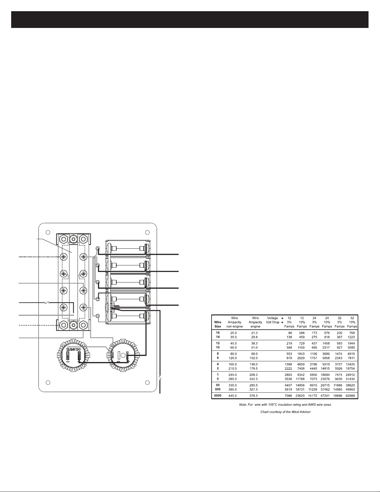
Wire Sizing Chart
1. Calculate the maximum sustained amperage of the circuit. Measure
the length of the circuit from the power source to the load and back.
2. Does the circuit run in an engine space or non engine space.
3. Calculate Famps (Feet x amps). Multiply circuit length by max. current.
4. Base the wire on either the 3% or 10% voltage drop. In general, items
which affect the safe operation of the boat and its passengers (running
lights, bilge blowers, electronics) use 3%; all other loads use 10%.
5. Starting in the column which has the right voltage and voltage drop,
run down the list until arriving at a value which is greater than the
calculated Famps. Move left to the Ampacity column to verify that the
total amperage of the circuit does not exceed the maximum allowable
amperage of the wire size for that row. If it does, move down until the
wire ampacity exceeds the circuit amperage. Finally, move left to the
wire size column to select the wire size.
Example
a. A 12 volt system at 10% drop with a 40’ circuit x 45 amps = 1800
Famps. A wire size of 8 is required.
3. Grounding metal electrical cases to prevent emission from inside
or absorption from outside of radio frequency noise (RFI).
ABYC requires that grounding wires be sized no smaller than one wire
size under that required for current carrying conductors supplying the
device to which the grounding wire is connected.
A full treatment of this subject is not possible within the scope of these
instructions and there is controversy surrounding the general subject of
DC bonding, of which DC grounding is a component. It is suggested
that installers not familiar with this subject consult one of the reference
books listed elsewhere in these instructions.
7. Apply branch circuit labels and mount panel
Apply a label for each circuit from the label set provided. If the
appropriate label is not included, extended label sets are available
through retail suppliers, and over 500 individual labels are available
directly from Blue Sea Systems. Please go to www.bluesea.com to
orderlabelsforspecicapplications.
Fasten the panel to the mounting surface using the screws provided.
8. Testing
Reconnect the main positive cable to the battery terminals and turn the
main switch on to supply power to the panel. Turn on all branch circuits
and test the voltage at the panel. Compare this voltage to the battery
terminal voltage to determine that the voltage drop is within 3%. With
all branch circuits still on, test the voltage at one device on each circuit
to determine that there is a 3% or 10% drop as is appropriate.
Optional Branch LEDs
This Panel is supplied with LEDs pre-installed in all optional branch
positions. For future expansion of the panels remove the positive leg of
the LED from the negative busbar and connect it to the load side of the
corresponding branch circuit breaker.
Note
This Blue Sea Systems electrical distribution panel is furnished with
15A circuit breakers for DC branch circuits. These ratings will satisfy
the vast majority of marine circit protection situations. As shown in the
Wire Sizing Chart, even 16 AWG wire, which is the minimum wire size
recommended by ABYC, has an allowable amperage greater than 20A.
The Purpose of a Panel
Therearevepurposesofamarineelectricalpanel:
• Power distribution
• Circuit (wire) protection
• Circuit ON/OFF switching
• Metering of voltage and amperage (in panels with meters)
• Condition Indication (circuit energized)
Other Innovative Products from Blue Sea Systems
• 360 Panel System
• Battery Management Solutions
• AC and DC circuit protection devices
• WeatherDeck waterproof circuit breaker panels
• Fuses, fuse blocks, and BusBar
• Analog and digital meters
CONNECT TO
(+) DC LOAD
CONNECT TO
(+) DC LOAD
CONNECT TO
(+) DC LOAD
CONNECT TO
(+) DC LOAD
TO DC
NEGATIVE
TO DC
NEGATIVE
TO DC
GROUNDING
SYSTEM
FROM DC
POSITIVE
FUSE
1.0 TO 2.0A
DC BACKLIGHT
BOARD
FROM DEVICE
GROUNDING
POINT
FROM DEVICE
NEGATIVE
CONNECT TO
(+) DC POSITIVE FEED
LED
LED
LED
LED
LED
LINE LOAD
15A
15A
15A
15A
15A
Other Blue Sea Systems Power Distribution Unit manuals


