NetPing 8/PWR-220 v4/SMS User manual

[ENG] NetPing 8/PWR-220 v4/SMS, User guide

[ENG] NetPing 8/PWR-220 v4/SMS, User guide -
2
Содержание
[8PWR] Copyright and Disclaimer .............................................................................. 5
[8PWR] Introduction ................................................................................................... 6
[8PWR] Device Overview............................................................................................. 7
Purpose of a Device............................................................................................................................ 7
Appearance ........................................................................................................................................ 7
[8PWR] Sockets and Indication Elements.................................................................. 8
GSM Slots............................................................................................................................................ 8
LAN Sockets........................................................................................................................................ 8
RS485 Socket...................................................................................................................................... 8
1W Sockets ......................................................................................................................................... 9
Power Supply Channels Status Indication ....................................................................................... 9
Power Supply Channels................................................................................................................... 10
Power Supply Inputs........................................................................................................................ 10
Sensor Plugin Terminals.................................................................................................................. 11
Reset Button..................................................................................................................................... 11
[8PWR] Power Supply Channels Management ........................................................ 13
Channels Management .................................................................................................................... 13
Inputs Reservation ........................................................................................................................... 13
Connecting a Load to Output Channels.......................................................................................... 13
[8PWR] Setting Parameters to Default Values (to the Factory Settings)................ 14
[8PWR] Using IO Lines for External Devices Management (in an Output Mode).... 15
Electric parameters of IO lines ........................................................................................................ 15
Equivalent Сircuit ............................................................................................................................ 16
[8PWR] Sensors Plugin.............................................................................................. 17
Sensors 1-Wire.................................................................................................................................. 17
Sensors of Dry Contact Type ........................................................................................................... 17
Leakage Sensors .............................................................................................................................. 17
Supply Voltage Sensor..................................................................................................................... 18

[ENG] NetPing 8/PWR-220 v4/SMS, User guide -
3
IR Transceiver IRC-TR v2 .................................................................................................................. 18
Plugging NetPing AC/DIN Sockets................................................................................................... 19
[8PWR] Shipping Kit .................................................................................................. 20
[8PWR] Operating and Storage Conditions ............................................................. 21
[8PWR] Warranty ....................................................................................................... 22

[ENG] NetPing 8/PWR-220 v4/SMS, User guide -
–

[ENG] NetPing 8/PWR-220 v4/SMS, User guide -[8PWR] Copyright and Disclaimer
[8PWR] Copyright and Disclaimer
–
[8PWR] Copyright and Disclaimer
The information, contained in this document, can be changed by a manufacturer without a prior notice.Although
every effort was made to make the information in this document accurate and without errors, a manufacturer is not
liable for their possible presence and for the consequences that may result from the errors herein. A manufacturer is
not liable if supplied equipment, software and this user guide does not correspond to expectations of a user and
his/her opinion about where and how to use all the above.All copyrights on supplied devices, described in this User
Guide, as well as firmware and software of devices and this User Guide belong to NetPing global Ltd. Сopying,
replication and translation of this user guide to other languagesare not allowed without a prior written permission
of a rightholder. Copying, replication, changing, disassembling of provided software are not allowed without a
prior written permission of a rightholder. For the part of software that is provided in source codes, there is a
separate license agreement, which defines an order of its use and modification. Other trademarks used in this
description belong to corresponding rightholders.
Developer and manufacturer:
NetPing east Co Ltd.

[ENG] NetPing 8/PWR-220 v4/SMS, User guide -[8PWR] Introduction
[8PWR] Introduction
–
•
•
•
[8PWR] Introduction
This user guide helps to become familiar with an operation of aNetping 8/PWR-220 v3/SMSdevice and get an idea
about its functionality and technical specifications as well as prepare a device for an operation.
A User Guide is designed for network administrators and users, who set up or operate a device. To work with a
device properly, a user must have an idea about the principles of building and functioning of local networks as well
as possess the next knowledge and skills:
Basic knowledge in the area of local and global networks;
Basicknowledgeintheareaofarchitectureandprinciples of work of TCP/IP networks;
Basic knowledge in the area of architecture and principles of work of Ethernet networks.

[ENG] NetPing 8/PWR-220 v4/SMS, User guide -[8PWR] Device Overview
[8PWR] Device Overview
–
[8PWR] Device Overview
In this section a purpose of a NetPing 8/PWRv3/SMS device is described as well as its appearance.
Purpose of a Device
A NetPing 8/PWRv3/SMS device is an IP PDU device on 8 independently managed power supply channels, divided
into two groups with four channels. A device's peculiarity is having two independent power supply inputs. Each
input allows to provide a power supply to one or both groups of 4 output channels. Switching channels between
power supply inputs can be done by a command from a web-interface of a device, from an SNMP interface of a
device, with the help of SMS-message or automatically when a power supply disappears on a main input.
Appearance
A device is designed in standard dimensions for installation in a 19' rack. A height of a device is 1U. Inputs and
output power supply channels are on a front and back panels of a device. Fasteners for mounting in a rack ("ears")
can be bolted toNetPing 8/PWRv3/SMS both front and back, which gives a possibility to mount a device in a rack by
any side. An appearance of device is shown on the pictures.
Front panel:
Back panel:
[ENG] NetPing 8/PWR-220 v4/SMS, User guide -[8PWR] Sockets and Indication Elements
[8PWR] Sockets and Indication Elements
–
[8PWR] Sockets and Indication Elements
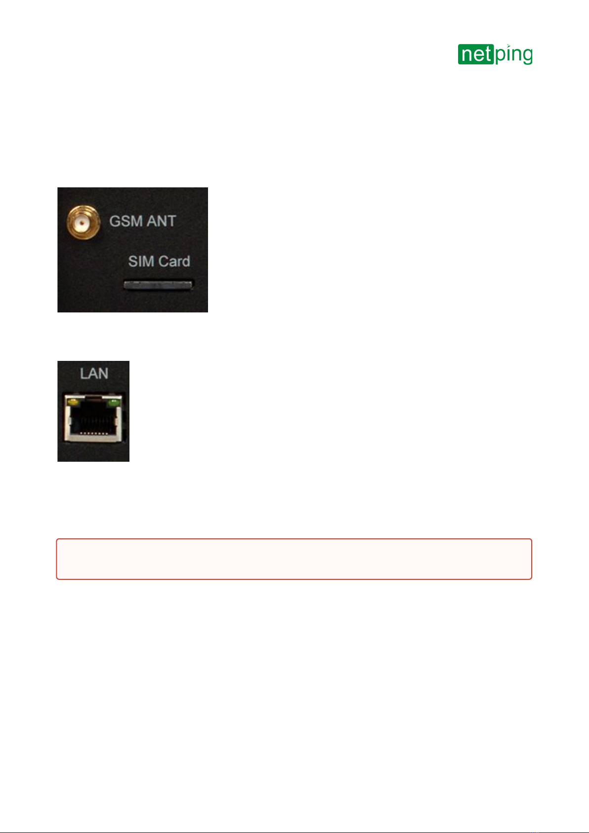
GSM Slots
There are GSMANT socketson a front panel on the left to connect an external antenna and aSIMCardslot to
install a SIM card.
LAN Sockets
Ethernet 10/100 BASE-T port. A device has two such ports: one on a front panel and another one on a back panel.
Together they form a dual port Ethernet-switch. One port is used for a network connection, another one is used for
additional equipment connection (another NetPing device, administrator's laptop, etc.), which gives an opportunity
to avoid installing of an additional switch on a remote site. The ports are equivalent, anyone can be used for a
network connection.
The Ethernet ports have two LEDs. A left one is CPU,its glowing means that a device is turned on, its blinking means
transferring packages to a network. A right one is Link,its lighting means having "link" on this port, its blinking
means receiving packages from a network.
RS485 Socket
An RS485 socket is used to connect RS485 devices. An RS485 port can work in one of two modes: either as an
RS485– Ethernet interface converter by a TCP protocol or in an electricity meter CE102 (Energy meter)protocol
analysis mode.
Important!Connecting both ports to an Ethernet switch with a disabled STP protocol will cause to creation of a
loop in an Ethernet segment.

[ENG] NetPing 8/PWR-220 v4/SMS, User guide -[8PWR] Sockets and Indication Elements
[8PWR] Sockets and Indication Elements
–
1W Sockets
1W sockets are used to plug sensors of a model line V4, which are built on a 1Wire technology.
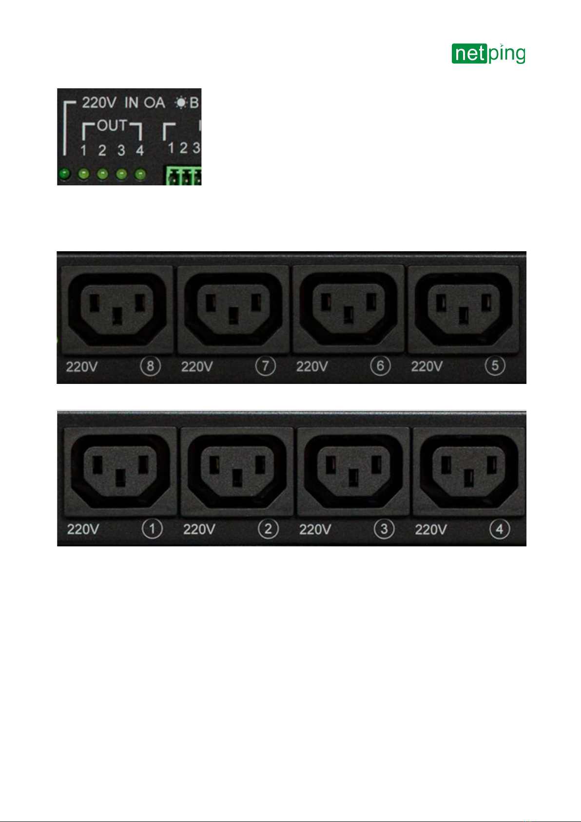
Power Supply Channels Status Indication
On a front panel there are LEDs that indicate a status of the second group of power supply channels. Channels 5 - 8
are included into this group. A status of each channel is represented by a corresponding LED of an OUT group. A LED
is glowing when there is a voltage on an output (a relay is closed).
220vINOB *A LED shows from what input the second group of channels is fed. A LED glows when a power supply is
fed from an input A, which is located on a back panel of a device.
On a back panel there are LEDs that indicate a status of the first group of power supply channels.Channels 1 - 4 are
included into this group. A status of each channel is represented by a corresponding LED of anOUTgroup. A LED is
glowing when there is a voltage on an output (a relay is closed).
220vINOA *B LED shows from what input the first group of channels is fed. A LED glows when a power supply is fed
from an inputB, which is located on a front panel of a device.
[ENG] NetPing 8/PWR-220 v4/SMS, User guide -[8PWR] Sockets and Indication Elements
[8PWR] Sockets and Indication Elements
–
Power Supply Channels
On a front panel there is the second group of power supply channels, with numbers of channels 5 – 8.
On a back panel there is the first group of power supply channels, with numbers of channels 1 -4.
Power Supply Inputs
On a front panel there is a power supply input B.

[ENG] NetPing 8/PWR-220 v4/SMS, User guide -[8PWR] Sockets and Indication Elements
[8PWR] Sockets and Indication Elements
–
On a back panel there is a power supply input A.
Sensor Plugin Terminals
On a back panel there is a terminal block for sensors plugin. Assignment of the terminals is from left to right: IO1,
IO2, IO3, IO4, SC, SD, +5V, GND.
Reset Button
AReset button is located on a back panel of a device. It is designed to reset settings to default values. To reset
settings, press the button Resetwith a sharp object and hold it while turning on a device.

[ENG] NetPing 8/PWR-220 v4/SMS, User guide -[8PWR] Sockets and Indication Elements
[8PWR] Sockets and Indication Elements
–

[ENG] NetPing 8/PWR-220 v4/SMS, User guide -[8PWR] Power Supply Channels Management
[8PWR] Power Supply Channels Management
–
[8PWR] Power Supply Channels Management
Channels Management
A NetPing 8/PWRv3/SMS device has eight independent power supply channels. Each channel is managed by a
normally closed relay. A relay and tracks have a big power capacity reserve, which provides a high resistance of a
device to overloading.
Each channel can be turned on or turned off independently from others by a command from a web-interface, by an
SNMP command or an SMS-message. Likewise it is possible to automatically turn on or turn off a power supply
channel according to a schedule or using a functionality of a Watchdog or a Logic. There is a need to remember that
when a channel is managed by a functionality of a Watchdog or a Logic, it cannot be turned on or turned off
manually (through a web-interface, SNMP, SMS).
Inputs Reservation
A device supports power supply inputs reservation. With this purpose, outputpower supply channels are divided
into two groups, with four channels in each one. Group 1 – channels 1 - 4, Group 2 – channels 5 - 8. For each group a
main input is set (1 or 2). Both groups can use the same input as a main one.
In cases of failure of a main input, a group of channels can be switched to a backup input - it is optional and is
configured in a web-interface of a device. After recovery of a main input a group of channels returns back to it either
automatically or by an administrator's command. This behavior is also programmed in a web-interface of a device.
Switching of a group of output channels from one input to another can be done from a web-interface, by an SNMP
command, SMS-message.
All switches between the inputs occur with a two-second power supply turning off of a group of channels.
Device's software guarantees consequent turning off (and consequent turning on) of output power supply channels
while switching from a main input to a backup one to reduce a value of the switched current.
Connecting a Load to Output Channels
When connecting a load to output power supply channels there is a need to take into account capacity limits of a
NetPing 8/PWRv3/SMS device. A maximum capacity of each channel separately is 1500 Watts. A maximum total
capacity of four channels in one group is 1725 Watts. I.e., if a consumer with a maximum capacity of 1500 Watts is
connected to a channel1, then it is possible to connect a total load no more than 225 Watts to channels 2,3,4.
Each input can provide 3500Watts, therefore both groups of power supply channels can be fed from one input
(1725Watts + 1725Watts = 3500Watts).

[ENG] NetPing 8/PWR-220 v4/SMS, User guide -[8PWR] Setting Parameters to Default Values (to the Factory Settings)
[8PWR] Setting Parameters to Default Values (to the Factory Settings)
–
•
•
•
•
•
•
•
[8PWR] Setting Parameters to Default Values (to the Factory
Settings)
Resetting parameters to the factory settings is necessary in the following cases:
A loss of a login and/or password to a web interface of a device;
A lack of information about current IP address of a device;
In some cases after a device software update.
A procedure of resetting parameters to the factory settings changes all customizable parameters of a device to the
default ones. (IP and MAC addresses, access filters, a user name, a password, etc.).
To reset parameters to default settings, fulfill the next actions sequentially:
Turn off a power supply of a device;
Press the Reset button (a button Set for a UniPing v3 monitoring unit);
Turn on a power supply of a device, continuing to hold Reset button pressed for 15-20 seconds;
Release the button. All parameters of a device are set to default settings.
After resetting parameters to default settings there is a need to do an initial configuration of a device.
On default, the next parameters of a device are set:
User name: visor
Password: ping
IP address: 192.168.0.100
Subnetwork mask: 255.255.255.0
Gateway: not set
SNMPcommunity: SWITCH
MAC-address: 00 a2 xx xx xx xx
Here xx xx xx xx corresponds to a serial number of a device. Thus, all devices after being manufactured have
unique MAC-addresses.

[ENG] NetPing 8/PWR-220 v4/SMS, User guide -[8PWR] Using IO Lines for External Devices Management (in an Output Mode)
[8PWR] Using IO Lines for External Devices Management (in an Output Mode)
–
•
•
•
•
•
•
•
•
•
•
•
[8PWR] Using IO Lines for External Devices Management (in an
Output Mode)
Input-Output (IO) lines of a device can be used for an input work as well as in an output mode for managing external
devices.
A device has four IO lines, corresponding to contacts I1 – I4 of a terminal block. Lines configuration for work as an
input or an output is made through a controlling web-interface of a device. All four IO lines can be customized
independently.
Lines management can be done by SNMP commands, URL-encoded commands, via a web-interface or using SMS-
commands (for devices with built-in GSM modem).
Such device functions as a watchdog and scheduled load management are NOT AVAILABLE for IO in an output
mode.
Examples of using:
Remote servers reboot – an imitation of pressing “reset”;
Remote management of an alarm, a light, a fan;
Management of an electric lock, electric gates on a remote object;
Management of smart home elements - watering flowers, opening-closing louvers, water pump, heating
boiler, heaters, etc.
Remote management of a power installation (diesel generator, gasoline).
It is acceptable to use intermediate relays with a power supply voltage 12 V from an external source. A ready socket
can be used for IO lines connection NetPing AC/DIN socket. In addition, we can advise ready assembly relays of
other manufacturers, which can be connected to our devices:
BM8070D a power relay 16А/250V for DIN-rail (check out the compatibility of this relay with the NetPing
device model on the relay web page on the site);
MP701 a power module switch (4 independent channels, 2 kW 10A each) (check out the compatibility of this
relay with the NetPing device model on the relay web page on the site);
For more detailed information, please contact a technical support[email protected].
Electric parameters of IO lines
In the «output» mode:
the voltage of logic «1»: +5 V, resistance: 3,3 kOhm;
the voltage of logic «0»: 0 V, resistance: 51 Ohm.
In the «input» mode:
the voltage of logic «1»: > 2,31 V;
the voltage of logic «0»: < 0,99 V.
Important!Correct electrical coordination of IO lines is required when connecting external executive devices.
Important! IO lines do not have galvanic isolation with a device! Remember about electrical safety when using
relays that commutate 220 V circuits. All work must be done by specialists with a correspondent qualification
who have a permit to work with such a voltage!

[ENG] NetPing 8/PWR-220 v4/SMS, User guide -[8PWR] Using IO Lines for External Devices Management (in an Output Mode)
[8PWR] Using IO Lines for External Devices Management (in an Output Mode)
–
Equivalent Сircuit

[ENG] NetPing 8/PWR-220 v4/SMS, User guide -[8PWR] Sensors Plugin
[8PWR] Sensors Plugin
–
[8PWR] Sensors Plugin
Sensors 1-Wire
Sensors 1-Wire (Temperature 1-wire, (THS), 2mandHumidity sensor 1-wire) connected to the connectors 1W plugs
RJ12, allowed to use extension cords or splitters. Maximum cable length 1-Wire network is limited to 50 meters.
Sensors of Dry Contact Type
Dry contact sensors are door opening sensors, buttons and other sensors, with a mechanism of work based on
opening/closing a conductor. A sensor is connected with two wires to an IO line of a device according to the table
(an order of plugging wires does not matter).
Sensor Flex NetPing 8/PWR-220 v4/SMS Terminal
First wire One of IO lines– 1/2/3/4
Second wire G
A sensor is packaged with an inseparable cable, withconnectors on the ends. A cable length can be increased with
the help offlat cable extenders of RC-4sensor, which are sequentially plugged one into another. Or it can be done
independently with the help of any wire with a minimum cross section of 0,4 mm2. Maximum allowable length of a
flat cable is 100 m.
Leakage Sensors
A leakage sensor is connected by a four-wire line according to the table.
Sensor Flex NetPing 8/PWR-220 v4/SMS Terminal
Green One of IO lines – 1/2/3/4
Yellow (White) G
Red +
Black G
Important! Sensors of a dry contact type, a supply voltage sensor, a leakage sensor, and others are plugged to
IOlines of a device. You can plug any four sensors out of this set.
Important! A corresponding IOline should be set to an input mode in settings of a device.

[ENG] NetPing 8/PWR-220 v4/SMS, User guide -[8PWR] Sensors Plugin
[8PWR] Sensors Plugin
–
A sensor is packaged with an inseparable cable, withconnectors on the ends. A cable length can be increased with
the help offlat cable extenders of RC-4sensor, which are sequentially plugged one into another. Or it can be done
independently with the help of any wire with a minimum cross section of 0,4 mm2. Maximum allowable length of a
flat cable is 100 m.
Supply Voltage Sensor
Asupply voltage sensor is plugged by a two-wire line according to the table.An order of plugging wires does not
matter.
Sensor Flex NetPing 8/PWR-220 v4/SMS Terminal
First wire One of IO lines – 1/2/3/4
Second wire G
A sensor is packaged with an inseparable cable, withconnectors on the ends. A cable length can be increased with
the help offlat cable extenders of RC-4sensor, which are sequentially plugged one into another. Or it can be done
independently with the help of any wire with a minimum cross section of 0,4 mm2. Maximum allowable length of a
flat cable is 100 m.
IR TransceiverIRC-TR v2
IR transceiver is plugged by a four-wire line according to the table:
Sensor Flex NetPing 8/PWR-220 v4/SMS Terminal
Labeled wire (red) C
Second wire after a labeled one D
Third wire after a labeled one +
Important! Sensors of a dry contact type, a supply voltage sensor, a leakage sensor, and others are plugged to
IOlines of a device. You can plug any four sensors out of this set.
Important! A corresponding IOline should be set to an input mode in settings of a device.
Important! Sensors of a dry contact type, a supply voltage sensor, a leakage sensor, and others are plugged to
IOlines of a device. You can plug any four sensors out of this set.
Important! A corresponding IOline should be set to an input mode in settings of a device.

[ENG] NetPing 8/PWR-220 v4/SMS, User guide -[8PWR] Sensors Plugin
[8PWR] Sensors Plugin
–
Sensor Flex NetPing 8/PWR-220 v4/SMS Terminal
Fourth wire after a labeled one G
A sensor is packaged with an inseparable cable, withconnectors on the ends. A cable length can be increased with
the help offlat cable extenders of RC-4sensor, which are sequentially plugged one into another. Or it can be done
independently with the help of any wire with a minimum cross section of 0,4 mm2. Maximum allowable length of a
flat cable is 100 m.
PluggingNetPing AC/DIN Sockets
When plugging a socket to a device, all wires are used except for a brown one. There is a need to switch an IO line, to
which a NetPing AC/DIN socket is connected, to the status "output". When a status of an IO line is logic 0, the socket
will have 220V, and a load will be turned on. When a status of an IO line is logic 1, a socket will be cut off power, and
a load will be turned off.
Sensor Flex NetPing 8/PWR-220 v4/SMS Terminal
Red +
Black G
Blue (Green) Одна из IO линий – 1/2/3/4
A relay with normally closed contacts is used to switch load in NetPing AC/DIN. This means if a control wire is not
plugged anywhere, 220V will be in the socket and a load will be switchedon.
A sensor is packaged with an inseparable cable, withconnectors on the ends. A cable length can be increased with
the help offlat cable extenders of RC-4sensor, which are sequentially plugged one into another. Or it can be done
independently with the help of any wire with a minimum cross section of 0,4 mm2. Maximum allowable length of a
flat cable is 100 m.
Important! A brown wire is not used and must stay unplugged!

[ENG] NetPing 8/PWR-220 v4/SMS, User guide -[8PWR] Shipping Kit
[8PWR] Shipping Kit
–
•
•
•
•
•
•
[8PWR] Shipping Kit
A shipping kit is shown at the picture:
A shipping kit includes:
A device NetPing 8/PWRv3/SMS;
An antenna;
A user guide;
A packing box;
A power cord – 2 pcs.;
Mating terminals – 2 pcs.
Other manuals for 8/PWR-220 v4/SMS
1
Table of contents
Other NetPing Power Distribution Unit manuals


Popular Power Distribution Unit manuals by other brands


Lex
Lex PowerHOUSE Series user manual

LEGRAND
LEGRAND 6 46910-CTO manual

Liebert
Liebert MP115HW user manual

Pepperl+Fuchs
Pepperl+Fuchs GUB Series Brief instructions

Schulte Elektrotechnik
Schulte Elektrotechnik EVOline Port 1129 Operating and assembly instructions

A-Neutronics
A-Neutronics MS-1917-LCD instruction manual


