P/N 003-460
Issue 6
Standard Recommended Procedure 003-460 | Issue 6 | October 2017 | Page 1 of 4
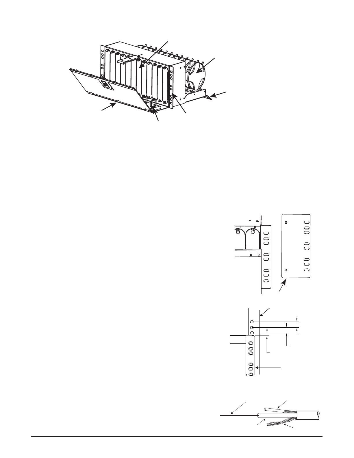
CCH 4U Horizontal Distribution Unit
(CCH-H4U)
1. Precautions
Laser Handling Precautions
Safety Precautions
Cable Handling Precautions
2. CARTON CONTENTS
• Horizontal distribution unit
• Hardware Kit containing:
• (1) Unit identication label
WARNING: Never look directly into the end of a ber that may be carrying laser light. Laser light is
invisible and can damage your eyes. Viewing it directly does not cause pain. The iris of the eye will not
close involuntarily as when viewing a bright light. Consequently, serious damage to the retina of the eye
is possible. Should accidental eye exposure to laser light be suspected, arrange for an eye examination
immediately.
WARNING: DO NOT use magniers in the presence of laser radiation. Diused laser light can cause eye damage
if focused with optical instruments. Should accidental eye exposure to laser light be suspected, arrange for an eye
examination immediately.
CAUTION: Recommend the use of safety glasses (spectacles) conforming to ANSI Z87, for eye protection from
accidental injury when handling chemicals, cables, or working with ber. Pieces of glass ber are very sharp and
have the potential to damage the eye.
CAUTION: The wearing of cut-resistant safety gloves to protect your hands from accidental injury
when using sharp-bladed tools and armored cable is strongly recommended. Use extreme care when
working with severed armor. There will be a sharp edge where armor is cut. To minimize the chance of
injury from the cut armor, cover the exposed edge with a wrap of electrical tape. To minimize the chance
of injury from sharp-bladed tools, always cut away from yourself and others. Dispose of used blades and
armor scrap properly.
WARNING: Isopropyl alcohol is ammable with a ashpoint at 54ºF. It can cause irritation to eyes on contact. In
case of contact, ush eyes with water for at least 15 minutes. Inhalation of vapors irritates the respiratory tract.
Exposure to high concentrations has a narcotic eect, producing symptoms of dizziness, drowsiness, headache,
staggering, unconsciousness and possibly death.
CAUTION: Fiber optic cable is sensitive to excessive pulling, bending, and crushing forces. Consult the cable
specication sheet for the cable you are installing. Do not bend the cable more sharply than the minimum
recommended bend radius. Do not apply more pulling force to the cable than specied. Do not crush the cable or
allow it to kink. Doing so may cause damage that can alter the transmission characteristics of the cable; the cable
may have to be replaced.
• (1) Label, 12 x 12 position
• (12) 1/4 x 4-in cable ties
• (4) 10-32 x 0.375-in Phillips screws
• (4) 12-24 x 0.5-in Phillips screws
related literature | Search www.corning.com/opcomm. Click on “Resources/Standard Recommended Procedures.”
003-460-FR Instruction, CCH 4U Horizontal Distribution Unit (CCH-H4U) (French)