Blue Seal SG 5EC Specification sheet

Instructions for use
and maintenance
Ed. 10/2008
SG 5EC
SD 5EC
SD 5EC BT
CHECK
C
CYCLE
START

2
DECLARATION OF CONFORMITY
The following
hereby declares underfull responsability that the following product
(type model)
to which this declaration refers, is conform with the following standards:
on the basis of what is foreseen by the Directives:
We decline any responsability for injuries or damage derived from machine misuse, abuse by others or improper machine maintenance or repairs.
2008
- date of issue -
DISHWASHING MACHINE
(product description)
EN 60335-1, EN 60335-2-58, EN 61000-3-2, EN 61000-3-3, EN 55014-1, EN 55014-2
73/23/CEE, 93/68/CEE - 98/37/CE - 89/336, 92/31, 93/68/CEE
Blue Seal
Ltd
Units 6&7 Mount Street - Business Park
Nechelles,Birmingham
Mount Street
B7 5QU
SG 5 EC - SD 5 EC - SD 5 EC BT ......................
General Manager

3
DISHWASHING MACHINE
○○○○○○○○○○○○○○○○○○○○○○○○○○○○○○○○○○○○○○○
○○○○○○○○○○○○○○○○○○○○○○○○○○○○○○○○○○○○○○○
The illustrations concerning these instructions are on the inside of the back cover
37842
Mod.
SG 5EC - SD 5EC
SD 5EC BT

4
ENG IMPORTANT
Becomethoroughlyfamiliarwiththecontentsofthimanualbeforeinstalling,settingup,adjustingandservicingdiswashermachine
Mod. SG 5EC - SD 5EC - SD 5 EC BT
Only contact an authorized technical center or BLUE SEAL in the event of breakdowns or faulty machine operation.
The manufacturer reserves the right to modify the
productswhenevernecessary,withoutaffectingtheir
main features.
INDEX
Important .............................................................. pag. 4
Overall dimensions .............................................. pag. 5
Technical data...................................................... pag. 7
Decription of the controls ..................................... pag. 8

5
OVERALL DIMENSIONS
10
CHECK
C
CYCLE
START
A
B
D
C
E
SG 5EC - SD 5EC 600 600 820 1005 330
SD 5EC BT 600 620 820 1030 330
Model
A B C D E

6
Water cons. per c.le
Tank capacity
Water supply
Cycle length
Boiler capacity
Boiler heating elem.
SG 5EC-SD 5EC 20 l 7,5 l 200÷400 kPa Ø 3/4"G. 3,5 l 60/120/180 s
SD 5EC BT 20 l 7,5 l 200÷400 kPa Ø 3/4"G. 3,5 l 60/120/180 s
SG 5EC-SD 5EC ø 31 mm 5°÷40°C 20 ÷90 % 50°÷60°C80°÷90°C
SD 5EC BT ø 31 mm 5°÷40°C 20 ÷90 % 50°÷60°C80°÷90°C
Drain pipe fitting
Relative humidity
Operat.and storage te
Wash temperature
Rinse temperature
TECHNICAL DATA
Net weight
Water inlet max. temp.
Noise level
Basket dimensions
Weight of packed mac.
SG 5EC-SD 5EC 50°C < 70 dB (A) 500 x 500 mm 58 kg 66 kg
SD 5EC BT 50°C < 70 dB (A) 500 x 500 mm 58 kg 66 kg
SG 5EC-SD 5EC 60/30/20 230V ~ 50Hz 3550 W 3000 W 2000 W 550 W
SD 5EC BT 60/30/20 230V ~ 50Hz 6550 W 6000 W 2000 W 550 W 200 W
Output in baskets/hour
Total power
Wash pump
Electrical connection
Tank heating elem.
Rinse pump

7
CONTROL PANEL
Fig. 1
LEGEND
IL) Line button ON/OFF
TR) Regeneration button ( only for models with "D")
LRCK) CHECK led light
LTV) Tank temperature led light
LC1) SHORT cycle led light
LC2) MEDIUM cycle led light
LC1+LC2) LONG cycle led light
CYCLE) CYCLE selection button
ST) START CYCLE button
CHECK
C
CYCLE
START
IL TR LRCK LTV LC1 LC2
ST

8
ENGLISH
ENGLISH
Part 1: General description and safety device
Part 2: For the Operator
Part 3: For Authorized and Qualified
Technicians

9
PARTICULAR RECOMMENDATIONS
FOR THE OPERATOR
- Do not operate the machine without having become fully
familiar with the contents of this manual and without having
acquired a comprehensive knowledge of the specific
techniques and machine controls.
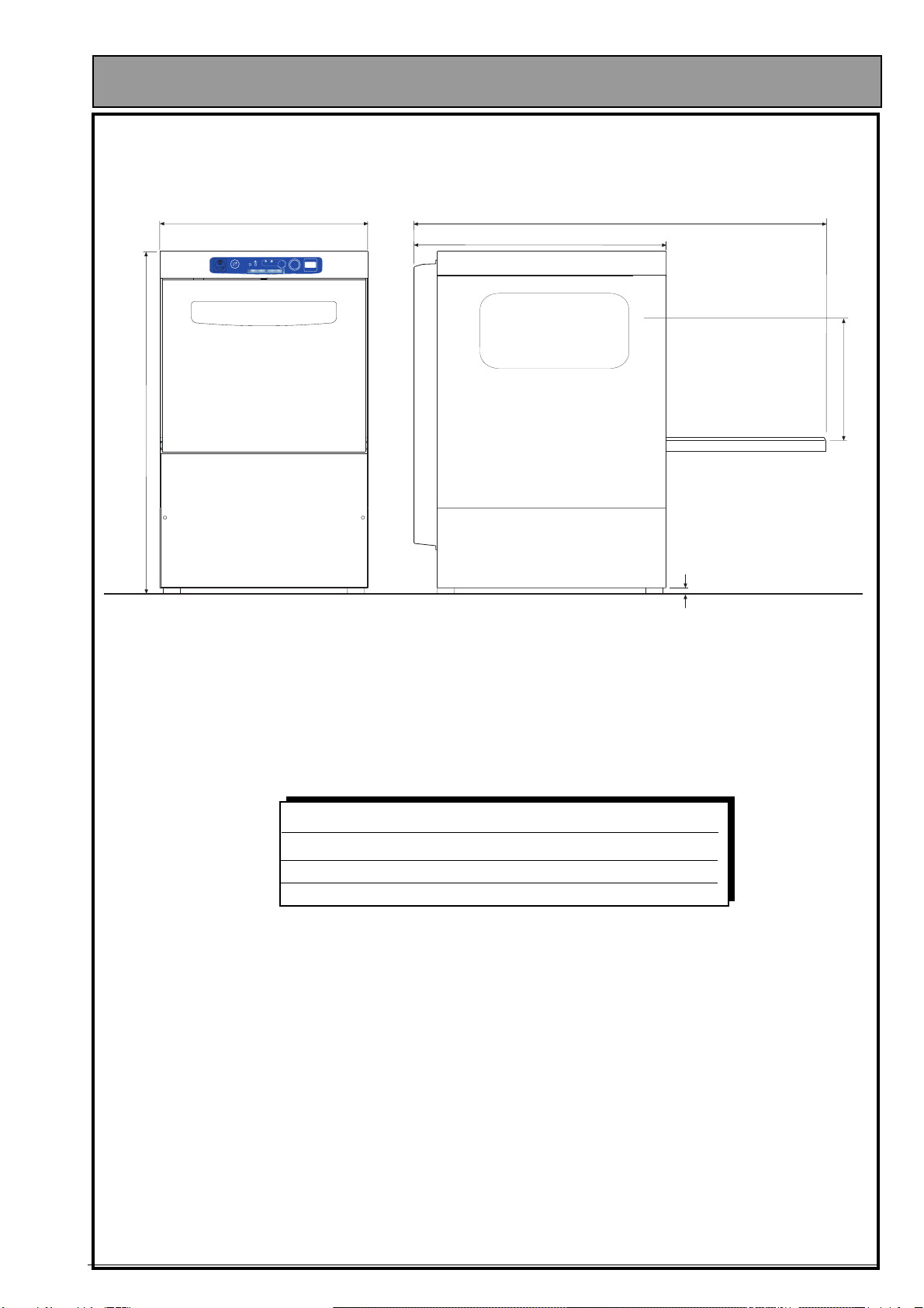
- Checkthat thearea inwhichthe machineis to beinstalled is
compatible with the dimensions of the machine itself before
installing this latter.
- Only use lifting and handling means that are suited to the
weightofthemachinewhenthismustbeinstalledorremoved
either completely or in part.
- Never allow unauthorized or unqualified personnel to start,
adjust, operate or repair the machine. Always refer to this
manual for the necessary operations.
- The mechanical parts and electrical/electronic components
situated inside the machine are protected by entirely closed
panels.
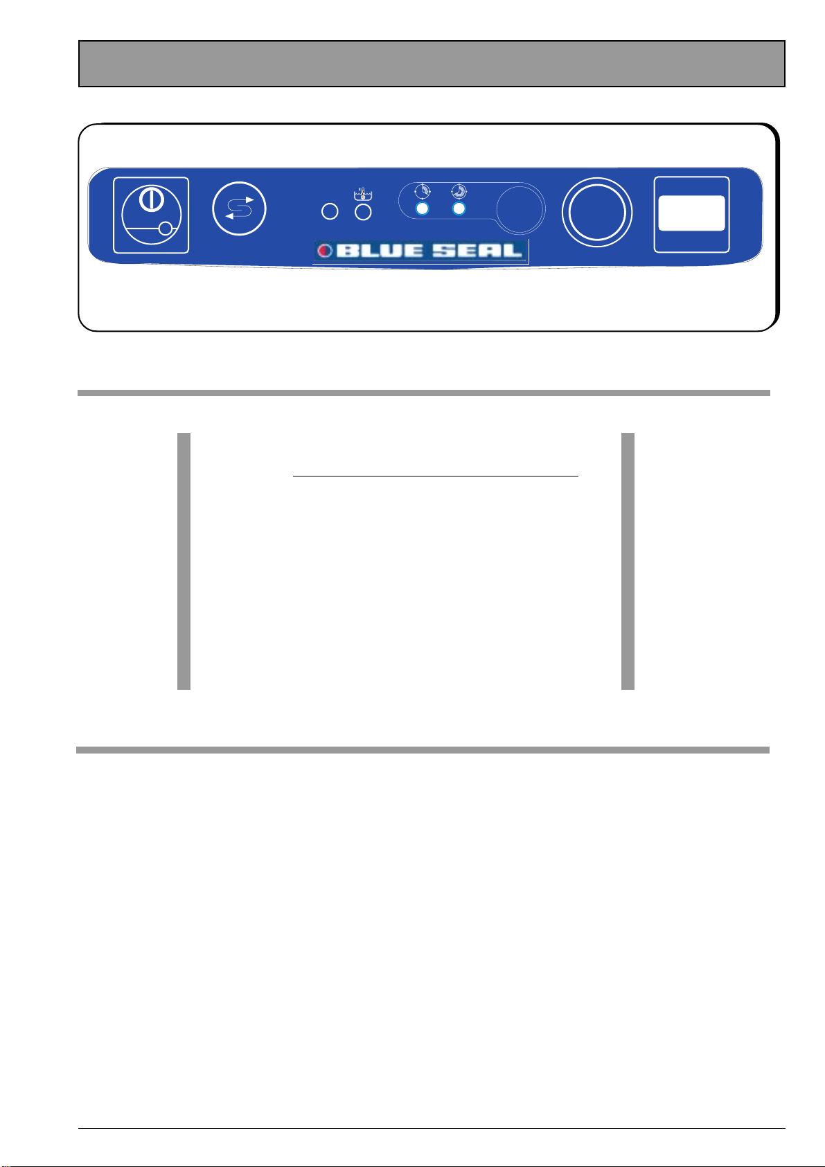
- Always ensure that the main switch has been set to the
“OFF”positionbeforecleaningand/orservicingthemachine.
This will disconnect the power source during the operator’s
intervention.
- The electrical powering system must be equipped with an
automatic release system prior to the main machine switch
and with a suitable grounding system that complies with all
the requisites established by industrial provisions for the
prevention of accidents.
- Always disconnect the power source if work must be carried
out on the main switch or in its vicinity.
- Allinspectionsandmaintenanceoperationsrequiringremoval
of the safety guards are carried out under the complete
responsibility of the users.
These operations should therefore only be carried out by
specialized and authorized technical personnel.
- Make sure that none of the accident preventing safety
devices(barriers,guards,casings,microswitches,etc.)have
been tampered with and that they are all perfectly functional
before operating. These devices should be repaired if this is
not the case.
- Never remove the safety devices.
- To prevent personal risks, only use power tools that are
correctlyconnectedtothegrounding tap andthatconform to
the national safety regulations.
- Neverevertamperwiththeelectricalsystemorwithanyother
mechanism.
- Never ever use the hands or unsuitable instruments to
locateleaks frompipes.Air, fluidsunderpressure orirritants
couldcauseseriousdamagetobothpersonsand/orproperty.
- Neverusethehandsinsteadofadequatetoolswhenoperating
the machine.
- Never use the hands or other objects to stop moving parts.
- PAY THE UTMOST ATTENTION TO THE DATA PLATES
AFFIXED TO THE MACHINE WHENEVER WORKING ON
THIS OR IN THEIR NEAR VICINITY.
- Theuser isobliged tokeepall thedata plates andstickers in
a legible condition.
- Never climb on to the door or on to the top of the machine.
- It is essential for the user to replace all data plates and
stickersthatmayhavedeterioratedforanyreasonorthatare
not clearly visible, ordering new ones from the Spares
Service.
- Contact the person in charge of maintenance in the event of
malfunctionsordamagetothemachinecomponentswithout
proceeding with further repairs.
- It is absolutely forbidden for anyone to use the machine for
purposes other than those explicitly established and
documented.Themachinemustalwaysbeusedintheways,
times and places dictated by common sense and the laws in
force in each country, even when there are no specific
provisions to govern the sector in the particular country of
use.
- Themanufacturerdeclinesallresponsibilityforaccidents
or damage to either persons or property as may arise
followingfailureto comply with either the relative safety
provisions or the instructions herein.
- These instructions, together with the provisions
governing machine installation and electrical
connections form an integral part of the Accident
Preventing Industrial regulations in force in each
individual country.
- THESESAFETYPROVISIONSINTEGRATEANDDONOT
SUBSTITUTE THE SAFETY PROVISIONS LOCALLY IN
FORCE.
- NEVER ever make hurried or inaccurate repairs that
could jeopardize the correct operation of the machine.
- ALWAYS ASK FOR HELP FROM SPECIALIZED
PERSONNEL IN CASE OF DOUBT.
- ANY TAMPERING BY THE USER RELIEVES THE
MANUFACTURER FROM ALL LIABILITY, THE USER
BEINGINTHISCASESOLELYRESPONSIBLETOWARDS
THE COMPETENT ACCIDENT PREVENTION
AUTHORITIES.
ENGLISH

10
1.1 GENERAL DESCRIPTION
Single-walled construction in 18/10 stainless steel with
fine satin finish.
All controls and electrical parts can be easily accessed.
The rinsing agent dispenser is built into the machine.
The washing rods and filters can be easily removed for
maintenance and routine cleaning.
All models are equipped with a safety microswitch on the
door.Theheating elementsaremade ofrustproofincoloy
steel.
All models are supplied with an adequate number of
baskets.
1.2 TYPE OF USE AND IMPROPER USE
These machines have been designed and built to wash
crockery placed in special baskets and using detergent
and rinsing agent.
• Permitted crockery: glasses, teacups, coffee cups,
saucers, cutlery made of materials suitable for
dishwashersandofasizeabletofitintothebasketand
machine.
• Use of specific detergents and rinsing agents for
industrial purposes normally available in the shops is
permitted.
ATTENTION
Anyimproperuseofthemachinerelievesthemanufacturer
from all and every responsibility for accidents or damage
to persons and property, also voiding all conditions of
guarantee.
1.3 TRANSPORT, SHIPMENT AND
STORAGE (Fig. 2)
- The machine is normally shipped in a cardboard box
closed by straps.
- Whentransportingthepackedmachine,usealifttruck
ortranspallet,positioning the boxonthe relative forks.
ATTENTION
The machine must be sheltered from the weather when
shipped and stored.
1.4 INSPECTIONS ON ARRIVAL
When the machine arrives, check that the packaging is in
a perfect condition and that there is no visible damage.
If everything is in order, remove the packaging (unless
other instructions have been received from the
manufacturer) and check that the machine is free from
damage caused by transport.
Now check whether there has been any damage to the
structure, crushing or breakages.
If damage or imperfections are discovered:
1 - Immediately notify the haulage contractor both by
phone and in writing by registered letter with return
receipt attached;
2 - Inform the manufacturer by registered letter
(with return receipt attached).
IMPORTANT
Notificationofdamageorfaultsmustbeimmediate,inany
casewithin 3daysfromthedateonwhichthemachine is
received.
1.5 UNPACKING (Figs 2-3-4)
Proceed in the following way in order to remove the
packing:
1. Cut the straps (7) that hold the cardboard in place.
2. Remove the box (8) by lifting it upwards.
3. Remove the protective film from the machine.
4. Removethemachinefromthebasebyliftingitfromthe
lower part of the casing (Fig. 4).
5. Allpackingmustbecollectedandnotleftwithinchildren’s
reach since it could become a source of danger. The
packing can be disposed of in the same way as solid
urban waste.
ATTENTION
Once the machine has been unpacked, NEVER ever use
the box containing the electrical components for lifting
purposes.
Lift the machine by raising it from the lower part of the
casing. Set it on the forks of a truck when transporting.
1.6 MACHINE IDENTIFICATION (Fig. 5)
- The serial number and machine data are stamped on
thedataplate(9)affixedtotherightpartofthemachine
itself.
IMPORTANT
Always state the model and serial number of the machine
when requesting technical assistance or ordering spare
parts.
1.7 DESCRIPTION OF THE SAFETY
DEVICES
• Models BLUE SEAL are equipped with a safety
microswitch that blocks the washing pump if the tub
access door is accidentally opened.
• The electrical parts are enclosed by panels locked by
screws.
• The machine is fitted with an equipotential ground
conductor.
• Safety overflow (21) to prevent water from spilling.
1.8 REFERENCE STANDARD
•The machine and its safety devices has been built in
compliance with the following standards:
•EssentialsafetyrequisitesestablishedbyDirective73/
23 EEC Annex 1 modified by Directive 93/68 EEC,
directive 89/336 EEC.
• Essential requisites established by Directive 2002/95/
EEC (RoHS).
ENGLISH Part 1: General description and Safety devices

11
ENGLISH
Part 2: For the operator
2.1 WASHING PHASES
2.1.a Switching on and Preparing the machine
To switch on the machine, press the power switch (IL)
into the ON position.
The LED indicating the last cycle selected will become
CONSTANTLYLIT (LC1 orLC2 or LC1 and LC2),as will
the CHECK LED and the tank temperature LED (LTV).
IMPORTANT
On first switching on, LED LC2 will light up.
Theboiler, and thenthetank, will starttofillautomatically.
Once the water level has been reached, the heating
elements will switch in, first in the boiler, then in the tank.
Once the water in the tank reaches the correct tempera-
ture, the tank temperature LED (LTV) will go ON.
WASHING OPERATION
If not equipped with an automatic dosing system, pour
into the tank a quantity of detergent suitable for the volu
me and hardness of the water. For quantities, refer to the
specific instructions for the detergent in use.
ATTENTION
When items to be washed are encrusted with burnt
on matter, or a long time has passed between use
and washing, it is essential to carry out a pre-was
soak using a suitable softening agent.
The use of hand-washing products is to be avoided
as they could produce foam inside the machine.
IPlacethebasketofitemstobewashedinsidethemachine,
having first removed any solid waste.
2.1.b Selecting a Cycle
The duration of the washing cycle can be chosen from
threedifferent lengthsoftime (SHORT,MEDIUM,LONG),
to be selected using the “CYCLE”button.
Eachtimethe“CYCLE” button is pressed, theLEDs LC1
or LC2 or LC1 and LC2 together, will light up or go out in
sequence as shown in the following table:
LC 1:SHORT CYCLE = 60 sec.
LC 2:MEDIUM CYCLE = 120 sec.
LC 1+LC 2:LONG CYCLE = 180 sec.
CHECK
C
CYCLE
START
2.1.c STARTING THE WASHING CYCLE
To start the washing cycle, press and hold the START
(ST) button for a few seconds, then release.
Throughoutthewashing cycle theLED(s)for the selected
cycle(LC1 orLC2 or LC1 and LC2 together) willFLASH.
ATTENTION
We recommend that you top up the detergent used up by
washinggreaseordispersedduringrinsingevery4-5com-
plete cycles.
The use of the machine ensures rinsing at the ideal tem-
perature for hygienic purposes every time;
Indeed, if the temperature is not sufficient the wash will
beautomaticallyprolonged soasto ensure thenecessary
conditions of optimum rinsing at 85°C.
The waiting time required to attain optimum temperature
can extend to a maximum of 8 minutes.
While this is taking place, the CHECK LED will FLASH
RAPIDLY until the end of the cycle. To reset the flashing,
switchthemachineoff andbackon usingthe powerswitch
(IL) .
2.1.d Interrupting the cycle
1)Itis possibletointerrupt the washingcyclemomentarily
by opening the door, this is an EMERGENCY measure:
the cycle LEDs (LC1 or LC2 or LC1 and LC2 together)
(blue) will start to FLASH, alternating with the CHECK
LED.
Onclosingthe door, operationswillresume fromthepoint
in which they stopped.
2) The cycle can also be interrupted by SWITCHING the
machine’s power switch (IL) to the OFF position.
3) On switching the machine back on, the LED indicating
the last cycle selected will light up.
At the end of the washing cycle, take out the basket
and shake it gently so as to remove the last drops left
on the washed items.
Allow items to dry and remove them from the basket with
clean hands.
Store all items on hygienic and completely stable surfaces.
2.1.e Manual Draining
It is possible to drain the water from the tank at any time
during the day, according to the waste accumulated.
To carry out this operation, proceed as follows:
- SWITCH the machine’s power switch (IL) to the OFF
position and release the overflow, allowing all the water
to drain from the tank;
- Remove the tank filters (22/23) and clean;
C
CHECK
CYCLE

12
ENGLISH Part 2: For the operator
Manual draining for machines with drainage pump
For machines fitted with a drainage pump itispossible
to empty the tank by carrying out the manual draining
cycle, during which only the drainage pump remains
active. IMPORTANT
This cycle can only be carried out by leaving the machine
SWITCHED ON with the tank full of water and the door
OPEN.
Having released the overflow, press and hold the
START (ST) button until the LED LC2 and CHECK
together)begins to FLASH, and then release the
START (ST) button;
The DRAINAGE CYCLE will begin.
IMPORTANT
By pressing the START (ST) button or switching the
power switch (IL) to OFF, you can interrupt the
drainage cycle before the preset time is up;
to restart the interrupted cycle, press START (ST)
again.
When the LC2 LED (blue) lights up CONSTANTLY,
the drainage cycle is finished.
At the end of the cycle, restore the filters (22/23) and the
overflow (21) to their respective positions.
2.1.f Switching off at the end of the day
At the end of the working day SWITCH OFF the
machine by pressing the power switch (IL) into the
OFF position.
Switch off the mains switch feeding the machine and
close the water supply taps.
For any repairs, contact only assistance centres
authorised by the manufacturer.
2.1.g Warnings during the operation
1) Ensure that the washing temperature remains at
approx. 55-60°C;
2)Avoid immersing bare hands in the detergent-filled
water; if this should happen, rinse immediately and
thoroughly with running water;
3) Use only anti-foaming detergents specific for use in
industrial machines;
4) Deactivate the machine in case of break-down or
malfunction.
For any repairs, contact only assistance centres
authorised by the manufacturer, and insist on the use
of original parts.
Failure to follow the above warnings may compromi
se the safety of the washing machine.
2.1.h Useful advice for better washibg results
Any unsatisfactory results from washing can be seen
when traces of dirt are left on dishes or other items; any
water marks may be caused by insufficient rinsing.
In this case, ensure that the rinsing nozzles (27) are clean
and that there is pressure in the water system.
If there are traces of waste, ensure that:
- The filters (22) (23) are clean;
- the water temperature is around 60°C;
- items are correctly positioned in the basket;
- the washing/rinsing nozzles are clean;
- the arms (24) rotate freely.

13
ENGLISH
Part 2: For the operator
2.2 CLEANING (Fig. 10)
2.2.a General information
Strictcompliancewiththemaintenanceinstructionsinthis
sectionwillkeepyourmachineinagoodworkingcondition
and will notably reduce the need for repairs.
ATTENTION
Ifanymachinecomponentbecomesfaulty,FIRSTCHECK
that all the instructions given in the previous paragraphs
have been complied with during use.
Repairs must be carried out immediately, as soon as the
fault occurs. This will prevent the trouble from becoming
worse and damaging other parts.
ATTENTION
Daily operations to carry out when work has ended, with
themachineOFF,themaincircuit-breakerdisconnected,
the water cocks off and the washing tub empty.
1. Thoroughly clean the inside parts of the machine.
2. Remove the filter (22) from the bottom of the machine
by releasing the overflow (21).
3. Remove the suction protection (23).
4. Wash the filters under running water and fit them
correctly back in their housings.
ATTENTION
Frequently check and clean the spraying units, removing
them from their housings and eliminating any dirt and
fouling. The frequency with which this operation must be
carried out depends on the quantity of dirt or on the
unsatisfactory washing results. Never use corrosive
productslikesodiumhypochlorite(bleach)orhydrochloric
acid, wire wool or steel brushes to clean either the inside
or outside parts of the machine.
2.3. PREVENTION MAINTENANCE (Fig. 10)
The preventive maintenance operations must be carried
out with the machine OFF, the main circuit-breaker
disconnected,thewaterdeliverycocksoffandthewashing
tub empty.
2.3.a Checking and cleaning the spray arms and
nozzles (Fig. 10)
Periodically check to make sure that the lower washing
armandrinsingarm(24)andtheir relativenozzlesarenot
clogged (26/27).
Cleaning the lower/upper unit
1. Unscrew the ring nut and lift the arm (24).
2. Wash the washing and rinsing arm.
If the nozzles (27) are clogged, unscrew them to
demountandclean,takingcaretopreventtheshapeof
the nozzle from being deformed. After cleaning, fit the
nozzles exactly back in their original positions.
3. Remount all parts by complying with the above
instructions in reverse.
2.4 DESCALING
Where hard water is present lime scale deposits will for
in the machine and on dishes, which must, for reasons of
hygiene, be removed by descaling.
Advice on operation procedures and frequency for this
treatment are generally given by the detergent supplier,
who can provide suitable products.
In order to avoid damaging the machine, do not
exceed recommended doses, follow the detergent
producer’s directions scrupulously and, having
finished operations, rinse thoroughly.
2.5 TEMPORARY STOPPAGE
If the machine is to be left inactive for a period of some
weeks, it is advisable beforehand to load the tank and run
a few empty cycles with clean water then drain, so as to
avoid the formation of unpleasant odours.
If necessary, repeat the process several times until the
water is still clean after washing.
If the stoppage is to be very long, it is advisable to
drain the water from the boiler and from the electric
pump.
2.6 DEMOLITION and DISPOSAL
When the machine is to be scrapped, drain the water
from the tank and from the boiler, as indicated in the
points above, and disconnect the machine from the water
and electricity supply networks, then dispose of the
components according to current regulations, respecting
national and local ecological and environmental
legislation, and taking care to separate the parts as
follows:
- metallic parts: body work, surfaces, panels, filters;
- electrical parts: motors, remote switches, micro-
switches, cabling;
- plastic parts: connectors, baskets;
- rubber parts: tubes, couplings
The producer declines all responsibility for any
printing errors contained in this booklet.
The instructions, drawings, tables and everything
else in this manual are of a confidential technical
nature. For this reason, none of the information may
beeithercompletelyorpartiallyduplicatedordisclosed
to third parties without prior written authorization
from BLUE SEAL which is the sole proprietor and
whichreservestherighttomakeanymodificationsas
may be considered necessary without advance
warning.

14
ENGLISH Part 2: For the operator
TROUBLESHOOTING
PROBLEMS CAUSES SOLUTIONS
The machine fails to
come on.
The machine does not fill
with water
Insufficient washing
Insufficient rinsing.
Main switch disconnected.
Water cock shut.
Fill pipe filter dirty.
Rinsing nozzles clogged.
Overflow pipe incorrectly inserted.
Washing filter dirty.
Washing nozzles clogged.
Washing rod clogged.
Insufficient or no detergent.
Machine temperature not reached.
Washing conditions insufficient.
Rinsing nozzles clogged.
Boiler clogged with scaling.
Low mains pressure (less than 200 kPa).
Temperature insufficient.
Incorrectly positioned nozzles or
nozzles deformed.
Turn on the switch.
Turn on the cock.
Detach the fill pipe (12 Fig. 6) and clean the filter (13).
Unscrew and clean the nozzles (27 Fig. 10) under running
water.
Make sure that the overflow pipe (21 Fig. 10) has been
correctly inserted.
Clean the filter (22/23 Fig. 10).
Demount and clean the washing nozzles under running
water (26).
Demount and clean the rod (24 Fig. 10).
Top up the detergent in the canister and check its
concentration.
Wait until the tank water has reached the right temperature
(50°C).
Make sure that the washing phase takes place correctly.
Unscrew the nozzles (27 Fig. 10) and clean them under
running water.
Contact the after-sales service.
Waituntilthepressurereturnsorpurchaseapressurepump.
Contact the after-sales service.
Make sure that the nozzles are in their correct positions.
Replace any damaged ones.
SUMMARY TABLE of CYCLE LED CHECK SIGNALS
MACHINE STATUS CYCLE LED CHECK
CYCLE: washing, pause, rinsing ON CONSTANT
ALARM: lack of heating RAPID flashing
ALARM: door open RAPID flashing
Manual drain ON CONSTANT
Regeneration cycle SLOW flashing
Machine off/standby OFF
*REGENERATION ALARM SLOW flashing
* Can only be stopped by starting the regeneration cycle, or if it has not been
programmed at all.

15
ENGLISH
IMPORTANT
Every operation of installation, electrical or hydraulic
connection, programming, maintanance etc...has to be
carried out by QUALIFIED personnel, authorised by the
manufacturer;
any interventions carried out by UNQUALIFIED
personnell, may compromise the technician’s own safety,
as well as the safety of other personnel (operators, etc.)
or of any other equipment connected to the washing
machine.
The manufacturer declines all responsibility for
accidents or damage to persons or property caused
by failure to comply with the above listed provisions.
3.1 INSTALLATION (Fig. 6-7)
- After having removed the packing, make sure that the
machine is in a perfect condition and that all the parts
have been included.
- Position the machine in the required setting.
3.1.a Connecting the drain pipe (Fig. 6)
- Fix the drain pipe (11) to the relative preset outlet.
IMPORTANT
It is essential to ensure that the drain pipe that it is not
throttled in any part.
3.1.b Connection to the water main (Fig. 6-7)
- Screw the end of the fill pipe (12) to a 3/4”G threaded
cock, fitting the filter (13 Fig. 7) in between.
ATTENTION
It is essential to connect the cold water delivery pipe to a
throttle cock in order to separate the water main from the
machine itself. Also make sure that there are no sharp
bends.
If there is sand in the water main, it will be necessary to
installafilterbetweenitandthemachine.Ifthewatermain
is without, it is advisable to install a decalcifier prior to the
machine with a setting of min. 4 and max. 8 French
degrees.
The manufacturer declines all responsibility for
damage to the machines caused by failure to comply
with the above listed provisions.
3.1.c Connection to the water main (Fig. 6-7)
DANGER
- Before connecting to the electricity main, always
check that the data pertaining to the power source
correspondtothoseindicatedontheidentification
plate(pos.9Fig.5)andthatthemainelectricpower
switch installed prior to the machine is
disconnected “0” OFF.
- An appropriately sized omnipolar circuit-breaker
with a minimum 3 mm gap between its contacts
must be installed between the power supply main
and the machine.
- The manufacturer declines all responsibility for
accidentsordamagetopersonsorpropertycaused
byfailuretocomplywiththeabovelistedprovisions.
• Connect the electrical power cable (14) to the main
switch installed prior to the machine.
• Connect the equipotential ground conductor to the
terminal (15).
3.2 DETERGENT DISPENSER (Optional)
(Fig. 8)
The machine is equipped with an automatic detergent
dispenser.
• Insert the red supply tube (16) into the canister (17).
ATTENTION
Always wash the hands under running water if they come
into contact with detergent, or comply with the specific
indications pertaining to the utilized type of detergent
itself.
• Proceed with a few no-load cycles until the intake and
delivery tubes have filled.
To adjust the dispenser, refer to the relative enclosed
manual and to the utilized type of detergent.
3.3 FILLING THE RINSING AGENT
DISPENSER (Fig. 8)
• Insert the transparent tube (18) into the canister (19)
containing rinsing agent.
• Start the machine as described in paragraph 2.1. The
dispenser will suck about 3 cm of liquid from the
canister.
• Fill during the cycle by opening (slightly) and closing
the door until the tube has completely filled.
3.3.a Adjusting the dose (Fig. 8)
• Start the machine as described in paragraph 2.1 and
hold a glass up to the light at the end of the cycle.
• Thedropsofwaterontheglasswillindicateinsufficient
dosage while streaks will indicate that dosage is
excessive either in relation to density or quantity.
• Regulate by means of the plug (20), turning clockwise
todecreasethequantityoranticlockwisetoincreaseit.
IMPORTANT
These data are indicative and not binding since they may
vary according to the hardness of the water or the utilized
type of detergent and rinsing agent.
ATTENTION
If the utilized product (detergent or rinsing agent) is
changed,itisadvisabletoflushoutthedosingsystemwith
water and to then proceed by filling the dispensers.
Part 3: For the technician

ELECTRICAL DIAGRAM
Ed. 02/2008
* Short circuit rinse check, Rinse check deactivated .
TABLE of ELECTRONIC TIMER FUNCTION
DIP-SWITCH FUNCTION TABLE
°see instruction for use
*
SG 5EC
SD 5EC
Start
2Min
17Min
2Min
2Min
20Sec
2'20"
Solenoid
valve regener
REGENERATION
Start
Wash pump
Pausa
Pause
10Sec
H2O Load
Drain pump
CYCLE
18Sec
20Sec
28Sec
TIMES DIAGRAM
5"
H2O Load
Drain pump
Pause
DIP
FUNCTION
1
23 4
ON
OFF
1
23 4
ON
OFF
1
23 4
ON
OFF
1
23 4
ON
OFF
CYCLE START MANUAL/AUTOMATIC
REGENERATION ABLE/DISABLE
WASH CYCLE SELECTION
75
70
65
60
0
45
50
55
115
110
105
100
80
85
90
95
ON
OFF
OFF
ON
OFF
OFF
OFF ON
ON
ON
OFF
ON
ON
ON
OFF
ON
OFF
ON
ON
ON
ON
OFF
OFF
ON
ON
ON ON
ON
ON
ON
ON
ON
OFF
OFF
ON
OFF OFF
OFF
OFF
OFF
OFF
OFF
OFF
OFF
OFF
ON
OFF
ON
ON
OFF
OFF
ON
OFF
OFF
ON
ON
OFF
OFF
ON
ON
ON ON OFF OFF
CYCLE COUNTER
12
MINIDIP
34
MINIDIP
12
MINIDIP
34
MODE MODE
2 STADIO 1 STADIO
TEMPERATUR
(50-87°C ) (38-78°C )
14
12
1121
22
24
22 24
11
12 14
21
Boiler thermostat connection
TEMPERATUR
TBA
TB
MINIDIP 1 MINIDIP 2 MINIDIP
3 4
MINIDIP
CYCLE START REGENERATION CYCLE
MANUAL OFF ACTIVATE ON 120/180 sec OFF ON
AUTOMATIC ON DISACTIVATE OFF
LEGEND
IL ON/OFF button
PR Pressure switch
LC Cycle light
LL Line light
LTV Tank temperature light
CP Door contact
TBA Auxiliary Boiler thermostat
TS Safety thermostat
TV Tank thermostat
TB Boiler thermostat
RB Boiler heating element
RV Tank heating element
MP Wash pump
ST START CYCLE button
SLC Cycle selector
FA Anti-disturbance filter
TR Regeneration button
EVC Hot water solenoid valve
EVR Regeneration solenoid valve
PS Drain pump (optional)
PD Detergent pump (optional)
PP Pression pump (optional)
CD Condensator 5 µF
C1 Boiler contactor
C1S Safety boiler contactor
CHECK
C
CYCLE
START
CP
PR
FA
C1 C1S
SCE
CHECK
C
CYCLE
START
BLACK
WHITE
ORANGE
DARK BLUE
DARK BLUE
PINK
RED
BLACK
TB
DARK BLUE
BROWN
BLACK
GREY
C 1
RED
C1S
WHITE
RED/BLACK
BROWN
GREY
BROWN
DARK BLUE
DARK BLUE
BLACK
PE
JELLOW/GREEN
WHITE/BLACK
TV
WHITE
TS
1
23 4
OFF
ON
1
2
3
4
5
6
7
8
9
10
CN2
CN3
SW1
RL2 RL3 RL4
8 A 8 A 16 A 16 A
RL1
VIOLET
TBA
ORANGE
CP
FA1
FA2
FA3
FA4
FA5
FA6
FA7
FA8
FA9
FA10
FA11
FA12
FA13
FA14
FA15
PRINTED CIRCUIT BOARD
(SCE)
BLACK
BLACK
WHITE
BLACK
BLACK
BLACK
PD PR
PS PP EVC
IL
230 V ~ 50Hz
CD
MP
~
DARK BLUE
RB
GREY
DARK
BLUE
RB RB
GREY
GREY
C1S
C1
NL1
FA
EVR
RV
BROWN

ELECTRICAL DIAGRAM
* Short circuit rinse check, Rinse check deactivated .
TABLE of ELECTRONIC TIMER FUNCTION
DIP-SWITCH FUNCTION TABLE
°see instruction for use
*
Start
2Min
17Min
2Min
2Min
20Sec
2'20"
Solenoid
valve regener
REGENERATION
Start
Wash pump
Pausa
Pause
10Sec
H2O Load
Drain pump
CYCLE
18Sec
20Sec
28Sec
TIMES DIAGRAM
5"
H2O Load
Drain pump
Pause
DIP
FUNCTION
1
23 4
ON
OFF
1
23 4
ON
OFF
1
23 4
ON
OFF
1
23 4
ON
OFF
CYCLE START MANUAL/AUTOMATIC
REGENERATION ABLE/DISABLE
WASH CYCLE SELECTION
75
70
65
60
0
45
50
55
115
110
105
100
80
85
90
95
ON
OFF
OFF
ON
OFF
OFF
OFF ON
ON
ON
OFF
ON
ON
ON
OFF
ON
OFF
ON
ON
ON
ON
OFF
OFF
ON
ON
ON ON
ON
ON
ON
ON
ON
OFF
OFF
ON
OFF OFF
OFF
OFF
OFF
OFF
OFF
OFF
OFF
OFF
ON
OFF
ON
ON
OFF
OFF
ON
OFF
OFF
ON
ON
OFF
OFF
ON
ON
ON ON OFF OFF
CYCLE COUNTER
12
MINIDIP
34
MINIDIP
12
MINIDIP
34
MODE MODE
2 STADIO 1 STADIO
TEMPERATUR
(50-87°C ) (38-78°C )
14
12
1121
22
24
22 24
11
12 14
21
Boiler thermostat connection
TEMPERATUR
TBA
TB
MINIDIP 1 MINIDIP 2 MINIDIP
3 4
MINIDIP
CYCLE START REGENERATION CYCLE
MANUAL OFF ACTIVATE ON 120/180 sec OFF ON
AUTOMATIC ON DISACTIVATE OFF
SD5 EC BT
LEGEND
IL ON/OFF button
PR Pressure switch
PRBT Break Tank pressure switch
LC Cycle light
LL Line light
LTV Tank temperature light
CP Door contact
TBA Auxiliary Boiler thermostat
TS Safety thermostat
TV Tank thermostat
TB Boiler thermostat
RB Boiler heating element
RV Tank heating element
MP Wash pump
ST START CYCLE button
SLC Cycle selector
FA Anti-disturbance filter
TR Regeneration button
EV Water solenoid valve
EVR Regeneration solenoid valve
PS Drain pump (optional)
PD Detergent pump (optional)
PP Pression pump (optional)
CD Condensator 5 µF
C1 Boiler contactor
C1S Safety boiler contactor
R1,R2,R3 Auxiliary relays
CP
PR
FA
C1 C1S
SCE
CHECK
C
CYCLE
START
BLACK
GREY
ORANGE
BLUE
BLUE
RED
BLUE
IL
WHITE/BLACK
PINK
BLACK
BROWN
R2
R1
EVR
CP
BLUE
BLACK BLUE
WHITE
BROWN
BLACK
TV
RV
(2kW)
BROWN
TB
GREY
BLUE
BLACK
PE
JELLOW/GREEN
TS
C 1 C1S
PRBT
BLUE
BLACK
BLACK
BLUE
BLUE
PINK
RED PINK
WHITE
PD EV
RED
BROWN
PP
~
M
1
23 4
OFF
ON
1
2
3
4
5
6
7
8
9
10
CN2
CN3
SW1
RL2 RL3 RL4
8 A 8 A 16 A 16 A
RL1
PRINTED CIRCUIT BOARD
(SCE)
FA1
FA2
FA3
FA4
FA5
FA6
FA7
FA8
FA9
FA10
FA11
FA12
FA13
FA14
FA15
VIOLET
VIOLET
TBA
WHITE/RED
R1
GREY
VIOLET
PINK
PS
R3
PR
R1
L1
MP
~
CD
M
RB RB RB
C1S
C1
N
FA
BLUE
GREY
BLUE
GREY
GREY
BLACK
BROWN
BLACK BLACK
BLACK
BLACK
R3
R2
R3
R2
CD
230 V ~ 50Hz
CHECK
C
CYCLE
START
Ed. 02/2008

R
✂
7
Fig. 2 Fig. 3
Fig. 5
Fig. 4
8
16 11
Fig. 6 Fig. 7
15
13 12 14
12
9
Type: ..........................
N°: ..............................
Weight: .........................
Date: ...........................
....... Volt ............... hz
....... Ph ............. Amp
................. kW
CE product
BLUE SEAL LTD
BIRMINGHAM 0121-3275575
CHECK
C
CYCLE
START
LIFT
LIFT

Fig. 10
Fig. 9
Fig. 8
16
19 18
17
CHECK
C
CYCLE
START
+
-
20
24
21
22
26
27
CHECK
C
CYCLE
START
IL TR ST
LRCK LTV LC1 LC2

37842
This manual suits for next models
2
Table of contents
Other Blue Seal Dishwasher manuals