Blue Sky Network Iridium C-1000A User manual
C-1000A
Iridium™ Satellite Phone System
Installation Guide
May 2012
Document Part # 100115
Revision 1.6

Blue Sky Network December 2006
COPYRIGHT
Copyright 2003 Blue Sky Network
All rights reserved. No part of this manual may be reproduced, stored or distributed without written
permission of Blue Sky Network.
Blue Sky Network reserves the right to change or update specifications without notice.
Publication Date: June 2003
Information in this manual is current as of publication or revision date. Specifications and operational
details are subject to change without notice, at the discretion of Blue Sky Network, LLC.
This manual is available in PDF format from our website or by contacting our office at:
Page ii C-1000A Iridium™ Satellite Phone System 100115
www.blueskynetwork.com
Phone: +1-858-551-3894
Fax: +1-858-551-3891
1298 Prospect Street, Suite 1D
La Jolla, CA 92037

December 2006 Blue Sky Network
REVISION HISTORY
Revision Number Date Author Document
Number
Notes
1.0
December 2003 Blue Sky Network 100115 -
1.1
02/17/2004 Blue Sky Network 100115 Application
Notes 4A/5A
1.2 04/30/2004 Blue Sky Network 100115 Included link to
9520 Guide
1.3
08/04/2004 Blue Sky Network 100115 MagnaStar
integration Info
1.4
10/18/2004 Blue Sky Network 100115 No warranty on
Modifications
1.5
12/14/2006 Blue Sky Network 100115 9520 link
updated
1.6
05/03/2012 Blue Sky Network 100115 End of Life
Watermark
added
100115 C-1000A Iridium™ Satellite Phone System Page iii

Blue Sky Network December 2006
Page iv C-1000A Iridium™ Satellite Phone System 100115
TABLE OF CONTENTS
INTRODUCTION........................................................................................................................................... 1
APPLICATION ............................................................................................................................................... 1
OVERVIEW................................................................................................................................................... 1
SYSTEM DESCRIPTION & OPERATION.................................................................................................... 2
SYSTEM DESCRIPTION ................................................................................................................................. 2
IRIDIUM SATELLITE NETWORK....................................................................................................................... 4
SYSTEM OPERATION ................................................................................................................................. 5
FAA/JAA APPROVAL.................................................................................................................................. 6
GENERAL .................................................................................................................................................... 6
INSTALLATION AND OPERATIONAL APPROVAL PROCEDURES .......................................................................... 6
INSTRUCTIONS FOR CONTINUED AIRWORTHINESS.......................................................................................... 6
ENVIRONMENTAL QUALIFICATION.................................................................................................................. 6
EQUIPMENT SPECIFICATIONS & DRAWINGS......................................................................................... 7
C-1000A MODEM UNIT................................................................................................................................7
C-1000A CABIN UNIT .................................................................................................................................. 8
SINGLE-CHANNEL ANTENNA ......................................................................................................................... 9
DUAL-CHANNEL ANTENNA.......................................................................................................................... 10
INSTALLATION & WIRING........................................................................................................................ 11
GENERAL INFORMATION ............................................................................................................................. 11
LICENSE REQUIREMENTS ...........................................................................................................................11
COOLING AIR REQUIREMENTS .................................................................................................................... 11
AIRCRAFT INTERFACES .............................................................................................................................. 11
EQUIPMENT REQUIRED BUT NOT SUPPLIED ................................................................................................ 11
WIRE HARNESS FABRICATION & INSTALLATION CONSIDERATIONS ................................................................ 12
ANTENNA & ANTENNA CABLE INSTALLATION ............................................................................................... 13
MODEM UNIT (MU) INSTALLATION ..............................................................................................................15
CABIN UNIT (CU) INSTALLATION ................................................................................................................. 18
WIRING DIAGRAMS.....................................................................................................................................21
SERVICE ACTIVATION ............................................................................................................................. 25
POST INSTALLATION PROCEDURES .................................................................................................... 26
SYSTEM PERFORMANCE VERIFICATION ....................................................................................................... 26
GROUND TEST & OPERATIONAL FLIGHT CHECK PROCEDURE ...................................................................... 27
MAINTENANCE ...........................................................................................................................................27
TROUBLESHOOTING................................................................................................................................28
MOTOROLA DIGITAL HANDSET MESSAGES .................................................................................................. 28
SYSTEM TROUBLESHOOTING ......................................................................................................................29
PRODUCT WARRANTY ............................................................................................................................ 30
INSTALLATION DRAWINGS..................................................................................................................... 32
WIRING HARNESS FOR BASE SYSTEM (107104)..........................................................................................32
MAGNASTAR INTEGRATION SETTINGS …………………………………………………………………… 35
INSTALLATION NOTES FOR BSN KITS 4A/5A.......................................................................................36
December 2006 Blue Sky Network
100115 C-1000A Iridium™ Satellite Phone System Page 1
INTRODUCTION
Application
This guide is applicable to the following components:
Part Number Component Description
100100 C-1000A Cabin Unit
100120 C-1000A Modem Unit
S67-1575-109 Iridium-tuned Single-channel Antenna
S67-1575-165 Iridium-tuned Dual-channel Antenna
Notes
Overview
The information contained in this manual describes the features, functions, technical
characteristics, components, approval procedures, installation considerations, setup
procedures, checkout procedures and instructions for continued airworthiness for a
C-1000A Iridium Phone System.
The information, drawings and wiring diagrams contained in this manual are
intended as a reference for engineering planning only. The drawings and
wiring diagrams contained herein do not represent any specific STC, Form 337
or Form 1 aircraft installation. It is the installer’s responsibility to create
installation drawings specific to the aircraft. This manual and the drawings and
wiring diagrams contained herein may not be used as a substitute for any
drawing package.

Page 2C-1000A Iridium™ Satellite Phone System 100115
SYSTEM DESCRIPTION & OPERATION
System Description
General
The C-1000A Satellite Phone System is a satellite communication system built to
operate over the Iridium Satellite Network. It provides worldwide, bidirectional
satellite voice and data communications.
The base configuration consists of a C-1000A Modem Unit that can be remotely
mounted in an avionics bay or other unobtrusive location with one or more cabin or
cockpit mounted telephone handsets and an L-Band Iridium-tuned Antenna mounted
on the upper surface of the fuselage.
The C-1000A Modem Unit houses the Motorola™ Iridium Transceiver along with
Blue Sky Network’s proprietary hardware and software that enables that transceiver
to reliably work within the aircraft’s power system and interface to a range of aircraft
voice and data communication systems.
The C-1000A Cabin Unit, although not a required component, is often the primary
user interface. It contains the Motorola digital telephone handset along with various
connectors, system status indicators, a hang-up cup that holds the handset and the
Subscriber Identity Module (SIM) card reader that identifies the user to the Iridium
satellite network and enables the phone to operate on that network account.
The Iridium-tuned antennas are L-band antennas tuned to the Iridium system
frequency of 1616 MHz to 1626.5 MHz. The antennas are TSO’d and qualified for
high-speed military and commercial aircraft.
The base configuration can be modified or upgraded to meet individual or aircraft
requirements by adding Modem Units and portable satellite phones for additional
independent phone lines, integrating different telephone handsets or antenna
configurations, etc. Individual component descriptions and specifications are
detailed in their respective sections.

December 2006 Blue Sky Network
Typical C-1000A System Block Diagrams
The following diagrams shows the C-1000A Satellite Phone System component
interconnection.
Single-Handset Installation
Multiple Handset “Party-Line” Installation
100115 C-1000A Iridium™ Satellite Phone System Page 3

Page 4C-1000A Iridium™ Satellite Phone System 100115
Iridium Satellite Network
The Iridium Satellite System is the only current provider of truly global, truly mobile
satellite voice and data solutions with complete coverage of the Earth (including
oceans, airways and Polar regions). Through a constellation of 66 low-earth orbiting
(LEO) satellites operated by Boeing, Iridium delivers essential communications
services to and from remote areas where terrestrial communications are not
available. The service is ideally suited for the aviation industry as well as industrial
applications such as heavy construction, defense/military, emergency services,
maritime, mining, forestry, oil and gas.
Satellites................................66 (plus 6 in-orbit backup satellites)
Orbital Planes........................6
Orbit Altitude..........................485 miles (780 kilometers)
Inclination of Orbital Plane ....86.4 degrees
Orbital Period ........................100 minutes, 28 seconds
Satellite Weight .....................1,500 pounds (689 kilograms)
Spot Beams...........................48 per satellite (30 miles in diameter per beam)
PSTN
PSTN
Internet
Internet Internet
Internet
Corporate
Network
Corporate
Network
Internet
Service
Provider
BSN
ComHub
Iridium
Gateway
Packet Data
Circuit Voice/Data
Voice
Data
Data
PSTN
PSTN
Internet
Internet Internet
Internet
Corporate
Network
Corporate
Network
Internet
Service
Provider
BSN
ComHub
Iridium
Gateway
Packet Data
Circuit Voice/Data
Voice
Data
Data

December 2006 Blue Sky Network
100115 C-1000A Iridium™ Satellite Phone System Page 5
System Operation
The C-1000A Satellite Phone System uses a 2-wire Plain Old Telephone System
(POTS) telephone, a 4-wire analog phone or the C-1000A Cabin Unit with the
Motorola Digital handset as the primary interface between the operator and the
system. However, a PC can be used for data communications via the PC’s serial port
connection to the Cabin Unit. System configuration procedures are covered in
Motorola’s Satellite Series 9520 Mobile Telephone User’s Guide. Not all features
listed in the 9520 User’s Guide are available in the C-1000A, since the system was
adapted for aviation. The Motorola 9520 guide can be found on the Internet through
the link http://www.blueskynetwork.com/Support/UserGuides.php.
Placing a Call
General
Since the Iridium phone is designed to operate from anywhere on the globe, the
Iridium phone network and phone numbers are configured like an independent
country. Every Iridium call must be dialed like an international call. You operate
the phone the same way no matter where you are located.
2-Wire POTS or 4-Wire Analog Phone
1. Enter the phone number in an international format as follows:
Pick up handset and verify you have dial tone, then dial 00 followed by
the Country Code, the City or Area Code and the Phone Number
Motorola Digital Handset (C-1000A Cabin Unit)
Reference Motorola’s Satellite Series 9520 Mobile Telephone User’s Guide for
instructions on using the C-1000A Cabin Unit Digital Handset
To place a call using the Motorola Digital Handset on the C-1000A Cabin Unit
1. Enter the phone number in an international format as follows:
Dial 00 or +followed by the Country Code, the City or Area Code and
the Phone Number
NOTE: The “+” sign is obtained by pressing and holding the 0+ key for a few seconds
2. Press the OK button. You will see “Calling” displayed on the handset
followed by the number you dialed
Receiving a Call
2-Wire POTS or 4-Wire Analog Phone
Reference the phone’s user manual, or try simply picking up the handset.
Motorola Digital Handset (C-1000A Cabin Unit)
To answer an incoming call, simply unlatch the handset or if you are using a
headset, press the OK button on the Motorola Handset. For further information,
reference Motorola’s Satellite Series 9520 Mobile Telephone User’s Guide for
instructions on using the C-1000A Cabin Unit Digital Handset.

Page 6C-1000A Iridium™ Satellite Phone System 100115
FAA/JAA APPROVAL
General
Acceptance for the installation and use of the C-1000A Satellite Phone System must
be sought through the appropriate offices of the Federal Aviation Administration
(FAA), Joint Aviation Authorities (JAA) or other certifying agency.
The C-1000A Satellite Phone System is approved by the FAA (Federal Aviation
Administration) as compliant with the airworthiness requirements as defined in 14
CFR (Code of Federal Regulations), Part 23.
STC Number: SA01329LA – Cessna 414A Series as amended July 15,2003
PMA #: PQ2389M
NOTE: The Motorola Digital Handset and SIM Card Reader have been considered
small parts by the FAA per FAR Part 25, Appendix F, Part 1, Paragraph (a).
(1).(v) as part of a single Cabin Unit Installation and therefore the single C-
1000A Cabin Unit installation meets the flammability requirements of FAR
25.853. The Handset Cord meets the requirements of FAR Part 25,
Appendix F, Part 1, Paragraph (a). (3)., Flammability Requirements for
Electrical Wiring.
Installation and Operational Approval Procedures
A functional ground test procedure and an operational flight check procedure should
be used to verify proper installation, functional performance and electromagnetic
compatibility with existing aircraft systems.
Instructions for Continued Airworthiness
The C-1000A components require no routine servicing or maintenance. The
installation has no additional overhaul time limitations.
Environmental Qualification
C-1000A Modem Unit
The C-1000A Modem Unit has been tested to DO-160D Section 21, Category M.
C-1000A Cabin Unit
The C-1000A Cabin Unit has been tested to DO-160D Section 21, Category M.
Single-Channel Antenna
The Single-Channel Antenna is qualified to DO-160, MIL-C-5541, MIL-E-5400, MIL-
STD-810 and TSO-C129.
Dual-Channel Antenna
The Dual-Channel Antenna is qualified to DO-160C, MIL-C-5541, MIL-E-5400, MIL-
STD-810 and TSO-C129a.

December 2006 Blue Sky Network
EQUIPMENT SPECIFICATIONS & DRAWINGS
C-1000A Modem Unit
Notes:
1. Dimensions are for Installation reference only.
2. Center of gravity (CG) is approximate and does not
include mating connectors or cables.
3. Dimensions are in inches. [Dimensions in brackets
are in millimeters]
4. Mating connector: Type DB-37P
5. Mating connector: Type DB-9S
6. Mating connector: Type TNC female
7. Nominal weight: 4.7lbs (2.12 kg) ±15%.
8. Power Input: (Two options available)
28 VDC nominal, 1 amp max
12 VDC nominal, 1.5 amps max
9. RF Interface:
Transmit Frequency: 1616 MHz – 1626.5 MHz
Input /Output Impedance: 50 ohms
Multiplexing Method: TDMA/FDMA
Max Transmit Power: 7 watts in transmit slot
Average Transmit Power: 0.6 watts during frame
100115 C-1000A Iridium™ Satellite Phone System Page 7
Page 8C-1000A Iridium™ Satellite Phone System 100115
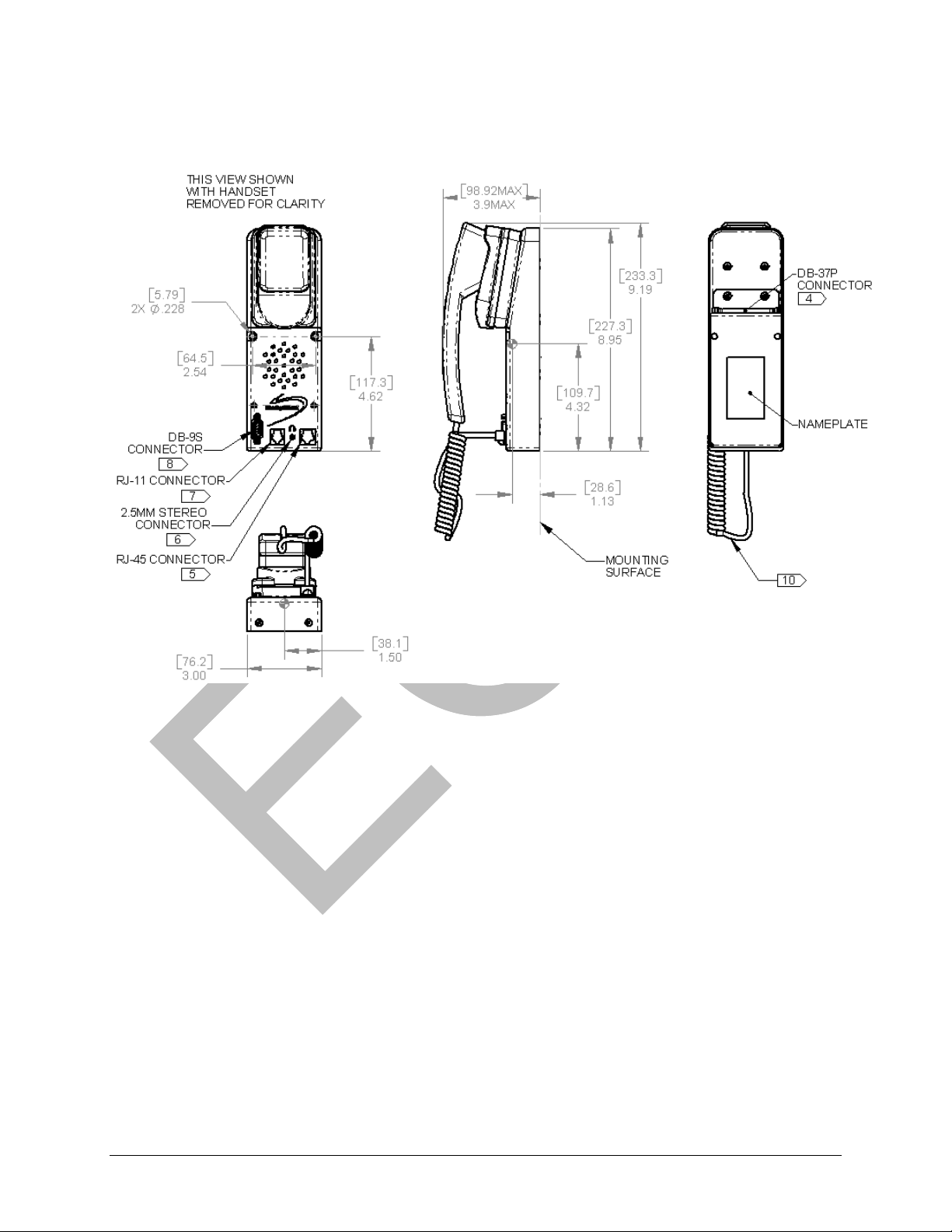
C-1000A Cabin Unit
Notes:
1. Dimensions are for installation reference only.
2. Center of Gravity (CG) is approximate and does not include mating connectors and cables or the
phone cord.
3. Dimensions are in inches. [Dimensions in brackets are in millimeters]
4. Mating connector: Type DB-37S
5. Mating connector: Type RJ-45 male (for Motorola Digital Handset)
6. Mating connector: Type 2.5mm stereo male
7. Mating connector: Type RJ-11 male – for 2-Wire POTS analog phone
8. Mating connector: Type DB-9P – for PC data port
9. Nominal weight: 1.8lbs (0.82 kg) ±15%.
10. Handset cord length is approx 12 inches [300mm] when coiled and 84 inches [2100mm]
maximum length when stretched
11. Power is supplied by the C-1000A Modem Unit.
12. No mounting orientation criteria. Designed for mounting on horizontal or vertical surfaces

December 2006 Blue Sky Network
Single-Channel Antenna
The antenna is a spherical-radius molded radome that provides protection against
rain, ice, and lightning strikes. It is qualified for high-speed military and commercial
aircraft and is designed to DO-160, MIL-C-5541, MIL-E-5400, MIL-STD-810 and
TSO-C129 standards.
Frequency (Iridium/GPS)..................1616 -1626.5 MHz / 1575 ±10MHz
VSWR...............................................1.5:1
Polarization.......................................Right Hand Circular Polarization (RHCP)
Impedance........................................50 ohms
Power Handling ................................60 watts CW
Gain ..................................................+3 dBic @ Zenith
Lightning Protection.......................... DC grounded
Weight...............................................6 oz.
Material............................................. 6061-T6 aluminum / thermoset plastic
Finish ................................................Skydrol resistant enamel
100115 C-1000A Iridium™ Satellite Phone System Page 9

Page 10 C-1000A Iridium™ Satellite Phone System 100115
Dual-Channel Antenna
The Dual-Channel antenna is available for aircraft with multiple Iridium phone
installations. The antenna is a low profile dual-element molded radome that provides
coverage from 1610 to 1626.5 MHz for excellent Iridium operations and 1530-1660.5
MHz for low gain data application. It is designed to DO-160C, MIL-C-5541, MIL-E-
5400, MIL-STD-810 and TSO-C129a standards and is qualified for high-speed
military and commercial aircraft.
Frequency
J1 ..................................1610 - 1626.5 MHz
J2 ..................................1530 - 1660.5 MHz
VSWR..................................2.0:1
Polarization..........................Right Hand Circular Polarization (RHCP)
Impedance...........................50 ohms
Power Handling ...................60 watts
Gain .....................................+3 dBic @ Zenith
Lightning Protection.............DC grounded
Weight..................................16 oz.
Material................................6061-T6 aluminum / thermoset plastic
Finish ...................................Skydrol resistant enamel

December 2006 Blue Sky Network
100115 C-1000A Iridium™ Satellite Phone System Page 11
INSTALLATION & WIRING
General Information
Generally, modification of the aircraft consists of installing one or more C-1000A
Satellite Phone Systems for passengers and crew to use while in the aircraft.
Alternate configurations may also include the installation of a dedicated or dual-
channel Iridium antenna with a connection for a carry-on portable Iridium phone. This
antenna and interconnect cable would hardwire the portable Iridium phone to this
external antenna to enable the operator to use the phone inside the aircraft and
during the flight.
NOTE: THE C-1000A SYSTEM REQUIRES PROFESSIONAL INSTALLATION.
License Requirements
The C-1000A Satellite Phone System has no licensing requirements.
Cooling Air Requirements
The C-1000A Satellite Phone System has very low power usage so forced air cooling
is not required for any of the components. However, units should be kept away from
heat sources.
Aircraft Interfaces
The C-1000A Satellite Phone System operates independent of aircraft navigation
systems. Therefore, no aircraft interface is required other than the 12 or 28Vdc
Power Input, Power Return and Chassis Ground.
Power Input
The only component of the C-1000A Satellite Phone Systems requiring aircraft
power is the C-1000A Modem Unit.
Either of two input connections can be used:
• 28 VDC nominal, 1 amp max at 27.5VDC (Input Range: 18 - 32 VDC)
• 12 VDC nominal, 1.5 amps max at 12VDC (Input Range: 10 - 15 VDC)
A single 3-amp circuit breaker is recommended to protect the aircraft power
distribution system. See the section on the Modem Unit Installation or the C-1000A
Modem Unit Equipment Specification & Drawing for details.
Equipment Required But Not Supplied
1. Circuit Breaker: Pull Type Required for C-1000A Modem Unit
2. Interconnect Wiring
3. Mounting Hardware

Page 12 C-1000A Iridium™ Satellite Phone System 100115
Wire Harness Fabrication & Installation Considerations
Referring to the appropriate section of this manual, assemble a wiring harness as
required for the installation. All wires must be MIL-SPEC in accordance with current
regulations. Two-conductor shielded wire must be used where indicated and be MIL-
C-27500 or equivalent specification. Shields should only be grounded at the Modem
Unit end of the interconnect cable. Other ends remain floating.
It is imperative that the correct wiring be used and that proper stripping, shielding,
grounding, crimping and soldering techniques be used at all times. Failure to correct
techniques may result in poor performance, electrical noise or unit failure.
Power Wiring
To assure that the C-1000A will operate properly down to its rated minimum input
voltage, ensure that power wires of at least the recommended size are connected in
accordance with the installation drawings. It is recommended that power and ground
wires are a twisted pair to reduce signal noise.
Ground Bonding
In order to assure installation characteristics match the DO-160 RF and Lightning
test conditions, ensure that ground wires of at least the recommended size are
installed and these wires are connected to a bonded aircraft ground.
Note: Both the Modem Unit and the Cabin Unit need to be grounded to the airframe
for proper operation. See Pinout tables for correct pin information.
Cable & Wire Harness Routing Considerations
The length and routing of cables must be carefully planned before starting the
installation.
Avoid sharp bends in the cable.
Do not locate the cable near aircraft controls.
Observe all appropriate sections of FAR Parts 23, 25, 27, and 29, as well as AC
43.13-1B and AC 43.13-2A. Damage caused by improper installation will void
product warranty.
In order to ensure optimum performance, the C-1000A and associated wiring
should be kept a minimum of three feet from high noise sources and not routed
with cables from high power sources.

December 2006 Blue Sky Network
Antenna & Antenna Cable Installation
For optimum performance, the antenna must be installed on the upper surface of the
aircraft fuselage, away from the vertical stabilizer and with an unrestricted view of the
sky down to eight degrees above the horizon (similar to a GPS antenna).
Transmission from the antenna may be affected by, and can affect the operation of
other systems and it is the installer’s responsibility to evaluate the location for any
possible RF interference. In particular, the Iridium frequency is near the allocated
GPS and Inmarsat band. The antenna should be at least 39 inches (1 meter) from
TCAS and Transponder antennas and any L-band antennas, particularly GPS.
Observe all appropriate sections of AC 43.13-1B and AC 43.13-2A.
Strict maximum attenuation requirements for the coax cable and connectors
that link the Antenna to the C-1000A Modem Unit must be observed. The signal
loss budget, including the antenna cable and all connector, from the antenna to the
C-1000A Modem Unit is < 2dB @1626MHz. The BSN Installation Kits include the
FAA approved low loss coax antenna cable sized to meet this requirement.
Single-Channel Antenna (S67-1575-109) Installation
The S67-1575-109 Single-Channel Antenna has a low profile, providing structurally
insignificant drag loads. The antenna is usually installed using four MS27039C1-10
attachment screws (10-32). However, each aircraft has unique airframe issues. The
installer is responsible for the decision on any antenna installation issue.
A 1.25-inch (32 mm) diameter penetration, drilled at installation, permits the antenna
coax connector to be fed into the aircraft. A doubler, provided with the antenna,
reinforces the 1.25-inch diameter penetration. The doubler is 0.040 inch (1.0 mm)
thick 6061-T6 aluminum alloy and creates an effective ring of 4.09 inches (104 mm).
The doubler is attached to the skin using sixteen NAS1097AD3 rivets. This doubler
may NOT be appropriate for your aircraft. The installation material required may
vary from aircraft to aircraft and is the responsibility of the installer to determine.
Doubler Plate
100115 C-1000A Iridium™ Satellite Phone System Page 13

Page 14 C-1000A Iridium™ Satellite Phone System 100115
Dual-Channel Antenna (S67-1575-165) Installation
The S67-1575-165 Dual-Channel Antenna has a low profile, providing structurally
insignificant drag loads. The antenna is usually installed using four MS27039C1-10
attachment screws (10-32). However, each aircraft has unique airframe issues. The
installer is responsible for the decision on any antenna installation issue.
A 1.25- inch (32 mm) diameter penetration, drilled at installation, permits the antenna
coax connector to be fed into the aircraft. No doubler plate is included with the dual
channel antenna, since each aircraft has a different shape and design.
Antenna Cable Installation
The C-1000A Satellite Phone System antenna cable must be routed from the
antenna to the C-1000A Modem Unit. The Modem Unit is generally installed in the
avionics bay of the aircraft or other location as determined by the installer.
Strict maximum attenuation requirements for the coax cable and connectors
that link the Antenna to the C-1000A Modem Unit must be observed. The signal
loss budget, including the antenna cable and all connectors, from the antenna to the
C-1000A Modem Unit is < 2dB @1626MHz. Maximum cable length is determined by
this specification. Measured Voltage Standing Wave Ratio, or VSWR, of the coax
cable assembly, antenna and any bulkhead feed-through adapter must be less than
1.5 to 1.
Note: The BSN Installation Kits include a 15-foot (4.6 m) FAA approved low loss
coax antenna cable sized to meet this requirement. In addition, Blue Sky
Network has custom cables lengths and configurations up to 60 feet (18
meters) long to meet your installation requirements. You can also request
that one or both end connectors be shipped uninstalled to ease cable routing.
Antenna Cable Routing Considerations
The length and routing of cables must be carefully planned before starting the
installation.
Avoid sharp bends in the cable. Exceeding the minimum bend radius of the
antenna coax cable may result in permanent degradation of the cable loss.
Do not locate the cable near aircraft controls.
Observe all appropriate sections of FAR Parts 23, 25, 27, and 29, as well as AC
43.13-1B and AC 43.13-2A
In order to ensure optimum performance, the C-1000A and associated wiring
should be kept a minimum of three feet from high noise sources and not routed
with cables from high power sources.

December 2006 Blue Sky Network
100115 C-1000A Iridium™ Satellite Phone System Page 15
Modem Unit (MU) Installation
The location of the C-1000A Modem Unit is at the option of the installer, but
consideration should be given to environmental conditions, distance from the
antenna and distance from the C-1000A Cabin Unit. The Motorola transceiver’s
operating specifications are limited to –20ºC to +60ºC.
Power Input
Either of two input connections can be used:
• 28 VDC nominal, 1 amp max at 27.5VDC (Input Range: 18 - 32 VDC)
• 12 VDC nominal, 1.5 amps max at 12VDC (Input Range: 10 - 15 VDC)
A single 3-amp circuit breaker is recommended to protect the aircraft power
distribution system.
2-Wire Analog POTS Telephone Interface
The C-1000A Modem Unit supports a standard 2-wire tip and ring loop (phone line).
See DB-37 “Cabin Unit” Connector pins 14 & 15. The RJ-11 connector on the C-
1000A Cabin Unit is wired to this circuit. This circuit enables the C-1000A Modem
Unit to interface to one or more 2-wire Plain Old Telephone Service (POTS) phones
that can be located around the aircraft. This includes 900MHz & 2.4GHz cordless
phones for even greater installation flexibility. If more than one POTS phone is
connected, all POTS phones can talk on the call, just as with residential extension
phones. You cannot join a POTS (analog) phone conversation using the Motorola
Digital Handset. The Motorola transceiver does not support simultaneous digital and
analog outputs.
Loop Battery Voltage.............................. -49 VDC Typical
Loop Resistance, Including Telephone .. 1000 Ohms Maximum
DC Loop Current .................................... 25 mA Typical
Ringing Signal ........................................ 20 Hz, Trapezoidal Waveform
Ring Voltage........................................... 65 Volt, 3 REN
Signaling................................................. Loop Start, DTMF (Dial Pulses Ignored)
AC Impedance........................................ 600 Ohms
Audio Band Pass.................................... 300 Hz to 3400 Hz
4-Wire E&M Analog Telephone/Audio Circuit Interface
The C-1000A Modem Unit provides an interface to a standard 4-wire E&M audio
circuit. Transmit audio originating at the user’s microphone or handset is applied to
the TX Input to the Modem Unit, while the Modem Unit’s RX Output delivers received
audio toward the user’s earpiece or handset. (The user must provide the appropriate
interface equipment between the user’s headset or handset and the Modem Unit.)
The Modem Unit’s audio output level is approximately 0 dBm maximum; the input
level to the Modem Unit should be similar. DTMF signaling is supported; dial pulse
signaling is not supported.
A call is originated or answered by applying a voltage of either polarity across the
optically isolated Hook Switch Inputs (P1-4 & P1-5 on the “Power” connector);
removing the applied voltage ends the call. The Modem Unit indicates an incoming
call by operating the Incoming Ring Indicator relay; isolated contacts provide a
normally closed (P1-8 on the “Power” connector) or normally open (P1-9 on the
Page 16 C-1000A Iridium™ Satellite Phone System 100115
“Power” connector) output with respect to the common lead (P1-7 on the “Power”
connector). The common lead is current limited to protect the relay contacts against
accidental short circuit events. Normal operating current through these contacts
should be no more than 100 mA at up to 60 VDC.
TX Input, Balanced Audio, Dry Circuit....... 10K Ohm (DB-37 Pins 18 & 19)
RX Output, Balanced Audio, Dry Circuit.... 600 Ohm (DB-37 Pins 16 & 17)
Discreet Hook Switch Inputs ..................... Optically Isolated, ±5 to ±60 VDC
(DB-9 “Power” connector pins 4 & 5)
Discreet Incoming Ring Indicator............... Relay Isolated, 100 mA, 60 VDC max
(DB-9 “Power” connector pins 7, 8 & 9)
Audio Band Pass....................................... 300 Hz to 3400 Hz
PC Data Port Interface
The C-1000A Modem Unit includes an interface that enables a standard PC to
access the Iridium Data Services for connection to the Internet or a corporate
network, thus allowing the user to browse the web, send and receive email and
transfer files. This capability requires the purchase of an optional Iridium Data Kit and
the installation of the included software on the user’s PC. Iridium Data Services can
be run on a computer using the Windows XP, 95, 98, NT 4.0, 2000 and ME
Operating Systems.
This interface is available via the DB-9 connector on the C-1000A Cabin Unit or can
be wired directly from the C-1000A Modem Unit to other convenient locations around
the aircraft. See DB-37 “Cabin Unit” Connector pins 1 thru 9.
C-1000A Modem Unit Pinouts
DB-9 “Power” Connector
PIN SIGNAL DESCRIPTION
1 POWER_GND Power Ground Return
2 28V_IN 28Vdc Power Input (Range: 18 - 32 VDC)
3 12V_IN 12Vdc Power Input (Range: 10 - 15 VDC)
4 E&M_IN4 E&M or Cockpit Audio: Originate/Answer (±5 to ±60 VDC)
5 E&M_IN5 E&M or Cockpit Audio: Originate/Answer Ground Return
6 AIRFRAME_GND Airframe Ground (Connect to Aircraft Ground) (NOTE 1)
7 E&M_OUT7 E&M or Cockpit Audio: Incoming Call Relay, Common
8 E&M_OUT8 E&M or Cockpit Audio: Incoming Call Relay, Normally Closed
9 E&M_OUT9 E&M or Cockpit Audio: Incoming Call Relay, Normally Open
Notes 1. Ground Cable to AIRCRAFT_ GND must be as short as possible to
ensure low inductance/resistance.
Table of contents


