BlueChip RE2 User manual

Page | 1
RE2
Single Board Computer
User Guide
Document Reference: RE2 User Guide
Document Issue: 2.2

RISC Engine II Table Of Contents
Page | 2
Contents
Copyright ............................................................................................................................................................ 4
Limitations of Liability ....................................................................................................................................... 4
Trademarks ......................................................................................................................................................... 4
Regulatory Statements ........................................................................................................................................ 5
Safety Warning for North America .................................................................................................................... 5
Manual Organisation .............................................................................................................................................. 6
Introduction ............................................................................................................................................................ 7
Functional Overview .......................................................................................................................................... 8
Specification ....................................................................................................................................................... 9
General Precautions .............................................................................................................................................. 10
Electro-Static Discharges .................................................................................................................................. 10
On-Board Battery ............................................................................................................................................. 10
Electromagnetic Compatibility ......................................................................................................................... 10
Mechanical Specifications .................................................................................................................................... 12
Connector Locations ............................................................................................................................................. 13
Optional Communications Module ................................................................................................................... 14
Connector Details ............................................................................................................................................. 15
P1 – Ethernet Connector ............................................................................................................................... 15
P2 – Dual USB Connector (Edge of Board) ................................................................................................. 15
P3 – USB Device .......................................................................................................................................... 16
P4/P15 – Power in Connector ....................................................................................................................... 16
P5 – Audio Connector .................................................................................................................................. 16
P6 – GPIO Connector ................................................................................................................................... 17
P7 – Utilities Connector................................................................................................................................ 19
P9 – Dual USB Connector (Header) ............................................................................................................. 19
P10 – RS232 Full Connector ........................................................................................................................ 20
P11 – RS232 & RS422/485 Connector ......................................................................................................... 20
P8 – Video Connector ................................................................................................................................... 21
System Software ................................................................................................................................................... 24
Operating Systems Supported ........................................................................................................................... 24
General Purpose I/O ......................................................................................................................................... 24
RE2 Graphical User Interface(GUI) ................................................................................................................. 25
System Firmware .................................................................................................................................................. 27
Operating System Settings ................................................................................................................................ 28
Splash Screen .................................................................................................................................................... 29
Display Configuration ...................................................................................................................................... 30
Custom Settings ............................................................................................................................................ 31
Firmware Update .............................................................................................................................................. 33
Maintenance ......................................................................................................................................................... 34

RISC Engine II Table Of Contents
Page | 3
Amendment History ......................................................................................................................................... 35
Appendix I: Options and Assembly Guidelines ............................................................................................ 36
RE2 Antennae Guide .................................................................................................................................... 41

RISC Engine II Introduction
Page | 4
Copyright
All rights reserved. No part of this publication may be reproduced, stored in any retrieval system, or transmitted,
in any form or by any means, electronic, mechanical, photocopied, recorded or otherwise, without the prior
permission, in writing, from the publisher. For permission in the UK please contact Blue Chip Technology.
Information offered in this manual is believed to be correct at the time of printing. Blue Chip Technology
accepts no responsibility for any inaccuracies. The information contained herein is subject to change without
notice. There are no express or implied licences granted herein to any intellectual property rights of Blue Chip
Technology Ltd.
Limitations of Liability
In no event shall Blue Chip Technology be held liable for any loss, expenses or damages of any kind
whatsoever, whether direct, indirect, incidental or consequential, arising from the design or use of this product
or the support materials supplied with this product. If this product proves to be defective, Blue Chip Technology
is only obliged to replace or refund the purchase price at Blue Chip Technology's discretion according to their
Terms and Conditions of Sale.
Trademarks
All trademarks and registered names acknowledged.
IBM, PC, AT and PS/2 are trademarks of International Business Machines Corporation (IBM).
AMD is a registered trademark of Advanced Micro Devices Inc.
MSDOS and WINDOWS are registered trademarks of the Microsoft Corporation.

RISC Engine II Introduction
Page | 5
Regulatory Statements
CE
This product has been designed and assessed to meet the essential protection requirements of the European
EMC Directive (2004/108/EC), the Low Voltage Directive (2006/95/EC), and the R&TTE Directive
(1999/5/EC) when installed and used in conjunction with the guidelines provided within this document.
[Note that compliance with the R&TTE directive is only required for those versions of the product equipped
with radio frequency interfaces].
FCC
NOTE:
FCC compliance of product versions equipped with radio frequency interfaces may require specific approval for
the finished products.
WARNING:
Changes or modifications not expressly approved by the manufacturer could void the user's authority to operate
the equipment.
Safety Warning for North America
If the power lead (cord) is not supplied with the computer, select a power lead according to your local electrical
regulations. In the USA use a 'UL listed' lead. In Canada use a CSA approved or 'cUL listed' lead.
Si le cordon secteur n'est pas livré avec l'ordinateur, utiliser un cordon secteur en accord avec votre code
electrique nationale. En l'Etat Unis utiliser un cordon secteur 'UL listed'. En Canada utiliser un cordon secteur
certifié CSA, ou 'cUL listed'.

RISC Engine II User Guide Organisation
Page | 6
Manual Organisation
This manual describes in detail the RE2 Product range.
We have tried to include as much information as possible but we have not duplicated information that is
provided in the standard Technical References, unless it proved to be necessary to aid in the understanding of
the product.
The manual is sectioned as follows:
Introduction;
Overviews, showing outline dimensions;
Layout, showing where the various connectors are located, and their pin-out details;
Firmware Setup
Maintenance details
We strongly recommend that you study this manual carefully before attempting to interface with the RE2 or
change the standard configurations. Whilst all the necessary information is available in this manual we would
recommend that unless you are confident, you contact your supplier for guidance.
IT IS PARTICULARLY IMPORTANT THAT YOU READ THE SECTION 'PRECAUTIONS' BEFORE
HANDLING ANY COMPONENTS INSIDE THE UNIT.
If you have any suggestions or find any errors concerning this manual and want to inform us of these, please
contact our Technical Services department with the relevant details.

RISC Engine II Product Summary
Page | 7
Introduction
The Blue Chip Technology RE2 (BCT-RE2) sets very high standards for integration of the processor, graphics,
memory, and I/O technologies together with a unique connection system for selected LCDs.
The BCT-RE2 was introduced with two CPU options, 600MHz and 720MHz. The 600MHz CPU was also
available as an extended temperature product. All RE2s are supplied with 256MB of SDRAM and 256MB of
NAND Flash. Further, additional NAND Flash can be added through either the optional μSD Card or optional
MMC socket, if fitted.
From 2015, the BCT-RE2 will have two new CPU options based on a 1GHz CPU, which will be offered as a
Standard temperature or an Industrial temperature board. Although the 600MHz and 720MHz options will no
longer be available, the 1GHz board is able to be clocked down to 600MHz and 800MHz for customers with
applications that may not suit the faster CPU. This can be achieved for Windows CE6 and EC7 via an updated
Graphical Utility
The BCT-RE2 can operate from 7V DC input through to 36V DC input. Power requirements will vary
depending on the LCD panel and other peripherals attached to the RE2.
For example with the older 600MHz BCT-RE2 with the U.R.T. UMSH-8173MD-1T 5.7” Combined LCD and
Touch Screen, the operational power requirements will vary between 5W for Windows CE6, without
applications running, up to 10W with applications running and peripherals attached. With the 1GHz CPU board,
power levels are comparable with the 720Mhz board, indeed running the same application will actually be
slightly lower power level on the 1GHz board, as the CPU will not be working as hard
On its own, the RE2 operates at approximately 2W without power saving.
The BCT-RE2 has the capability to support a Lithium Battery via connector P14 to retain time when the unit is
powered off.

RISC Engine II Overview
Page | 8
Functional Overview
The following block diagram shows the key components of the RE2
OMAP
E
t
h
e
r
n
e
t
U H
t e
i a
l d
i e
t r
y .
B
a
t
t
e
r
y
P
o
w
e
r
E
E
P
R
O
M
GPIO
x12
(1.8V
- 5V)
Touch
Screen DVI LCD SD
Card
CM
Module
Connector
RAM
NAND
Camera
Bluetooth
WiFi
USB Host
x 4
RS485
RS-232
Full
RS-232
2 wire
USB
Device
Audio
GSM
MIC
Line
IN
Line
OUT
Ant-
enna
Ant-
enna
CM
Module
Connector
Ant-
enna
Power
Accelerometer
GPS
GSM / GPRS
GSM Audio
Ant-
enna

RISC Engine II Overview
Page | 9
Specification
• Texas Instruments OMAP DM3730 Applications Processor
• 256 MB SDRAM soldered onboard
• 256 MB NAND Flash soldered onboard
• Optional μSD Card NAND Flash Storage
• Video Controller - 18 bit RGB TTL
• 4 wire Touchscreen Controller
• 10/100 Ethernet including magnetics
• Quad USB 2.0 Hosts
• Single USB 2.0 Device
• Dual RS-232 (1 Full, 1 2-wire)
• Single RS-485
• Audio Codec Interface
• Battery backed Real-Time Clock
• 12 GPIO lines
• Utilities connector
• Wide Input Voltage – 7 to 36 volts (note: Input current is restricted to 1.6A maximum)
• Low power consumption – typically 2 watts (LCD not included)
• Bluetooth Class 2
• 802.11 b/g Wi-Fi
• Camera Interface
• Comms Interface (CM Module – GPS, GPRS)

RISC Engine II Precautions
Page | 10
General Precautions
Your Single Board Computer is susceptible to damage by electrostatic discharges. In order to avoid damage,
you should work at an anti-static bench and observe normal anti-static precautions. Wear an anti-static wrist
strap connected to an earth point before opening any packaging.
Where a wrist strap is not available, discharge any static charge you may have built-up by touching an earth
point. Avoid any further movement that could build up another static charge. Touch an earth point from time to
time to avoid further build-up, and remove the items from their anti-static bags only when required
Electro-Static Discharges
If you are going to open up the unit, it is important to realise that the devices on the cards within this unit can be
damaged by static electricity. Bear in mind that the damage caused by static electricity may vary from total
destruction to partial damage, which may not be immediately obvious. This could have an effect on the
product's reliability and warranty. Before opening the chassis, ensure that you take necessary static precautions.
Ideally you should work at an anti-static bench and wear an approved wrist strap or if that is not possible, touch
a suitable ground to discharge any static build up before touching the electronics. This should be repeated if the
handling continues for any length of time.
If it is necessary to remove a board or electronic assembly, place it into an anti-static bag. This will prevent any
static electricity build up damaging the board. Metallised bags are preferred. Do not use black anti-static bags
for any item containing a battery because these tend to be conductive and will discharge the battery.
On-Board Battery
The processor board can be fitted with a Lithium battery. Great care should be taken with this type of battery. If
the battery is mistreated in any way there is a very real possibility of fire, explosion, and personal harm. Under
NO circumstances should it be short-circuited, exposed to temperatures in excess of 100°C or burnt, immersed
in water, recharged or disassembled.
Expired batteries remain hazardous and must be disposed of in a safe manner, according to local regulations.
Le panneau de processeur est équipé d’une batterie de lithium. Le grand soin devrait être pris avec ce type de
batterie. Si la batterie est mistreated il y a de dans de toute façon un possibility très vrai du feu, d’expolosion et
de mal personnel. Dans au cunes circonstances il est sous peu circuité, exposé aux températures au dessus de
100 degrés de centrigrade ou brûlé, immergé dans l’eau, rechargée ou dissassambled.
Les batteries expirées restent dazaedous et doivent être reejetées d’une façon sûre, selon des règlements locaux.
Electromagnetic Compatibility
This product has been assessed operating in representative, standard configurations. As with any PC product,
however, final installation & configuration can vary significantly, and so the following guidelines are offered to
help ensure that compatibility is maintained.
All components added to a system should either carry appropriate equivalent levels of compliance, or
be tested for compliance as part of the final system, and should be installed in accordance with supplier
recommendations.
The external enclosure should be securely fastened (with standard lids and covers in place) to ensure
good metal-to-metal contact around the internal electronics

RISC Engine II Precautions
Page | 11
Any metal back plate must be securely screwed to the chassis of the computer to ensure good metal-to-
metal (i.e. earth) contact.
Metal, screened, connector bodies should be securely connected to the enclosure.
The external cabling to boards causes most EMC problems. It is recommended that any external
cabling to the board be totally screened, and that the screen of the cable connects to the metal end
bracket of the board or the enclosure and hence to earth. Round, screened cables with a braided wire
screen are used in preference to those with a foil screen and drain wire. Wherever possible, use metal
connector shells that connect around the full circumference of the cable screen: they are far superior to
those that earth the screen by a simple “pig-tail”.
The keyboard and mouse will play an important part in the compatibility of the processor card since
they are ports into the board. Similarly, they will affect the compatibility of the complete system. Fully
compatible peripherals must be used otherwise the complete system could be degraded. They may
radiate or behave as if keys/buttons are pressed when subject to interference. Under these
circumstances it may be beneficial to add a ferrite clamp on the leads as close as possible to the
connector. A suitable type is the Chomerics type H8FE-1004-AS.
USB cables should be high quality screened types.
Ensure that the screens of any external cables are bonded to a good RF earth at the remote end of the
cable.
Failure to observe these recommendations may invalidate the EMC compliance

RISC Engine II Installation
Page | 12
Mechanical Specifications
Outline Dimensions
RISC Engine II Installation
Page | 13
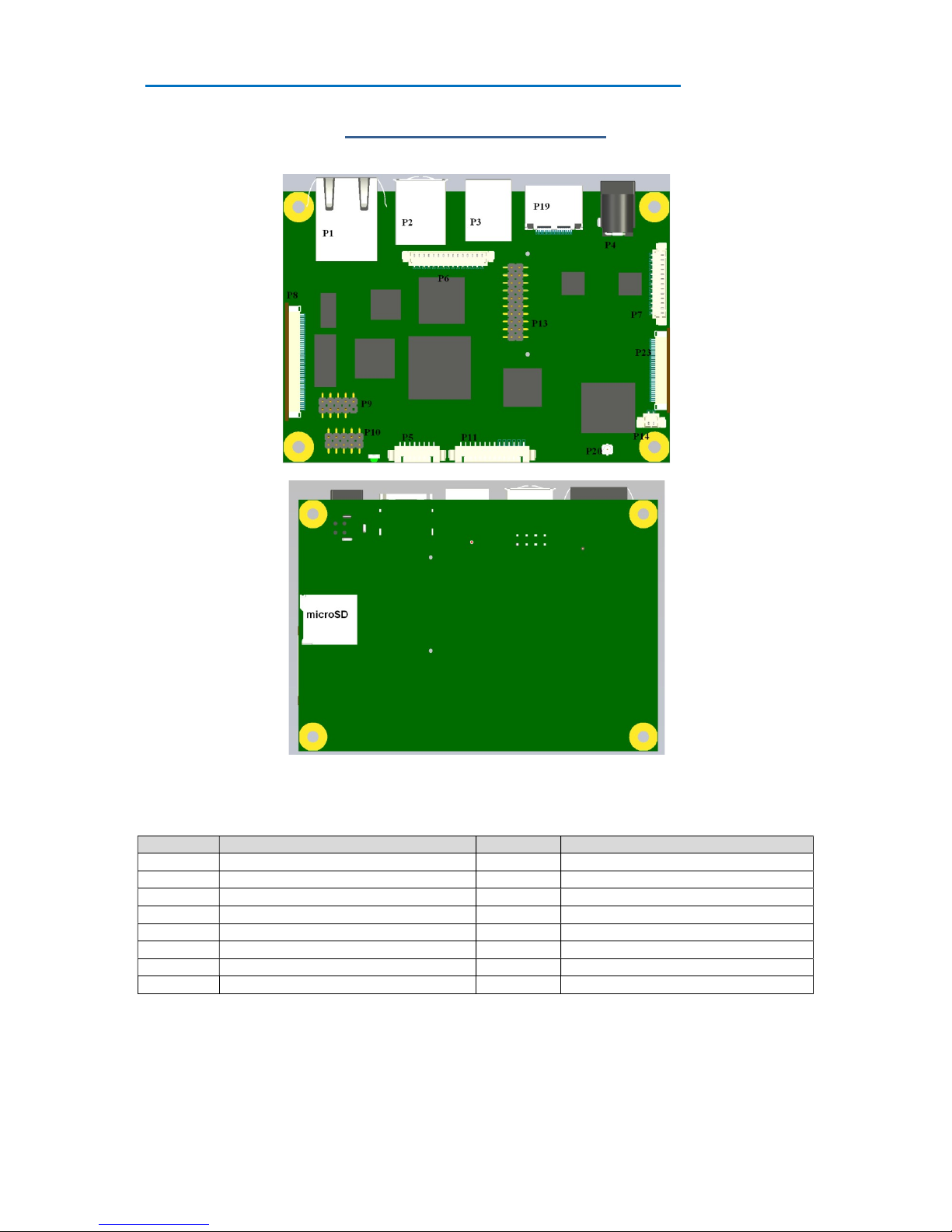
Connector Locations
Connector Description Connector Description
P1 RJ45 Ethernet P2 USB-A x 2
P3 USB-B P4 / P15 Power Input
P5 Audio P6 GPIO
P7 Utilities P8 LCD Video
P9 USB x 2 P10 RS232 (COM3)
P11 RS232 (COM2) and RS422/485(COM1) P13 Connection to CM module
P14 Battery P23 Camera
P20 Wifi and BlueTooth Antenna
Note: Not all connectors may be fitted
COM2 is a 2 wire device and can be reserved for Debug use only via the Configuration utility
RISC Engine II Installation
Page | 14
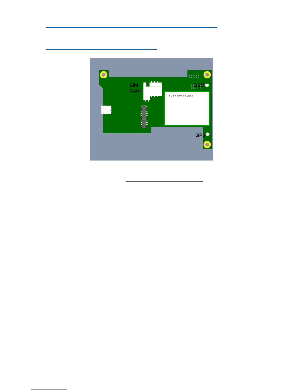
Optional Communications Module
The connections to the Communications Module consist of connectors for GSM and GPS Antennae, and a
socket for a SIM Card. Refer to the end of Appendix 1 for more details on Antennae

RISC Engine II Installation
Page | 15
Connector Details
P1 – Ethernet Connector
Pin Signal External Connections
(RJ45)
Comments
1 TD+ 1 Transit Data +ve
2 TD- 2 Transit Data -ve
3 CTT - Centre Tap Transmit
4 Ground - Electrical Ground
5 Ground - Electrical Ground
6 CTR - Centre Tap Receive
7 RD+ 3 Receive Data +ve
8 RD- 6 Receive Data –ve
9 VCC3 - Pull up to 3.3 volt VCC
10 LNK/#ACT - Link/Activity LED
11 SPD100# - Speed LED
12 VCC3 - Pull up to 3.3 volt VCC
13 Ground - Electrical Ground
14 Ground - Electrical Ground
P2 – Dual USB Connector (Edge of Board)
Pin Signal Comments
1 VBUS +5 volts – Filtered & current limited
2 D1- USB 1 Data Negative
3 D1+ USB 1 Data Positive
4 Ground Filtered Electrical ground
5 VBUS +5 volts – Filtered & current limited
6 D2- USB 2 Data Negative
7 D2+ USB 2 Data Positive
8 Ground Filtered Electrical ground

RISC Engine II Installation
Page | 16
P3 – USB Device
Pin Signal Comments
1 VBUS +5 volts – Filtered & current limited
2 D- USB 1 Data Negative
3 D+ USB 1 Data Positive
4 Ground Filtered Electrical ground
P4/P15 – Power in Connector
The RE2 has the option to be powered from either a 2.5/5.5mm Power Jack (P4) or a 2 Pin Screw Terminal
(P15)
P15
Pin 1 Ground
Pin 2 Vcc
The green shaded area on the left is the Screw Terminal. Pin 1 is the square VIA (i.e.
Ground is towards the front edge of the board)
P5 – Audio Connector
Pin Signal Comments BCT Cable Colour
1 Line Out Right Audio Output Right Channel
Green
2 Line Out Left Audio Output Left Channel
3 Audio Ground Audio Ground
4 Line In Left Audio In Left Channel
Blue
5 Line In Right Audio In Right Channel
6 Audio Ground Audio Ground
7 Audio Ground Audio Ground Red
8 Microphone IN Mono Audio Input

RISC Engine II Installation
Page | 17
P6 – GPIO Connector
The GPIO interface is a flexible, logic-level port providing a mix of dynamically-configured hardware inputs
and outputs. It is designed for use within a chassis with localised electronics. Interfacing to signals which may
pick up noise transients will require buffering and/or conditioning circuits.
Pin Signal Comments BCT_15Way_Cable_Pin
1 VCC_GPIO Reference supply input 8
2 GPIO 1 Input/output 1
3 GPIO 2 Input/output 9
4 GPIO 3 Input/output 2
5 GPIO 4 Input/output 10
6 GPIO 5 Input/output 3
7 GPIO 6 Input/output 11
8 GPIO 7 Input/output 4
9 GPIO 8 Input/output 12
10 GPIO 9 Input/output 5
11 GPIO 10 Input/output 13
12 GPIO 11 Input/output 6
13 GPIO 12 Input/output 14
14 [Not used] - 7
15 0V_GPIO Tied to RE2 circuit ground 15
The GPIO outputs are designed for flexibility, and will interface to electronics operating with signal levels
between 2.3V & 5.5V DC. The function and direction of the GPIO signals is configured by RE2 software (see
the software manual for details of GPIO port mappings and configuration).
Basic electrical characteristics are as follows:-
Feature: Pin(s): Min: Max: Units:
V
CC_GPIO
Supply Voltage VCC_GPIO 2.3 5.5 V
V
IH
Input High Voltage GPIO 1 .. GPIO 12 V
CC_
GPIO
– 0.4 V
CC_
GPIO
V
V
IL
Input Low Voltage GPIO 1 .. GPIO 12 0 0.15 V
V
OH
Output High Voltage GPIO 1 .. GPIO 12 V
CC_
GPIO
* 0.67 - V
V
OL
Output Low Voltage GPIO 1 .. GPIO 12 - 0.4 V
ICC Supply Current VCC_GPIO - 12 µA
Quiescent output current in the high state appears equivalent to a 10K pull-up (short-duration current boosting is
applied, however, during signal transitions to speed up rise/fall times). Optimum performance is achieved with
short cable connections, and minimum capacitive loading on the signal lines.
GPIO VCC
The original release of the RE2 required I/O voltage to be provided to the RE2 at the VCC_GPIO pin
(referenced to 0V_GPIO). In 2012, the Rev 3 release of the SBC allowed for the option to provide VCC from
the RE2 itself.

RISC Engine II Installation
Page | 18
In order to convert the RE2 to provide GPIO VCC, it is necessary to solder a link across two pads as shown
LK7 is on the underside of the PCB just above the green fuse (F2).

RISC Engine II Installation
Page | 19
P7 – Utilities Connector
Power Wake
1 Power_Off# 8 Wake#
2 Ground 9 Ground
Reset Battery
3 Reset# 10 No connect
4 Ground 11 No connect
Serial Bus Setup
5 Serial Clock 12 Setup#
6 Serial Data 13 Ground
7 Ground
P9 – Dual USB Connector (Header)
Pin Signal Comments
1 VBUS +5 volts – Filtered & current limited
2 VBUS +5 volts – Filtered & current limited
3 D- USB 3 Data Negative
4 D- USB 4 Data Negative
5 D+ USB 3 Data Positive
6 D+ USB 4 Data Positive
7 Ground Filtered Electrical ground
8 Ground Filtered Electrical ground
9 Key Removed
10 NC Not connected

RISC Engine II Installation
Page | 20
P10 – RS232 Full Connector
Pin Signal Comments
1 XDCD3# COM 3 Data Carrier Detect
2 XRX3 COM 3 RX
3 XTX3 COM 3 TX
4 XDTR3# COM 3 Data Terminal Ready
5 0 volts Electrical ground
6 XDSR3# COM 3 Data Send Ready
7 XRTS3# COM 3 Ready To Send
8 XCTS3# COM 3 Clear to Send
9 XRI# COM 3 Ring indicator
10 +5 volts Fused voltage rail
P11 – RS232 & RS422/485 Connector
Pin Signal Comments
1 0 volts Electrical ground
2 RS232 RX COM 2
3 RS232 TX COM 2
4 +5 volts Fused voltage rail
5 0 volts Through 10K pull down
6 VCC Through 10K pull up
7 Termination 120R + 100nF link to pin 10
8 CRX1N
9 CRX1N Same signal as pin 8
10 CRX1P
11 CTX1N
12 CTX1P
With COM1 RS422/RS485 operation in a multi drop network, the Transmit Line is only enabled when the DTR
line is enabled. Refer to the CE 6 User guide for more details
Table of contents
Other BlueChip Motherboard manuals


