MKS Robin Nano User manual

广州谦辉信息科技有限公司
Guangzhou Qianhui Information Technology Co.,Ltd.
MAKER BASE
QQ Discussion Group:489095605 232237692
E-mail:Huangkaida@makerbase.com.cn
Document Version:1.0
Release date
:
2018-10-13
MKS Robin Nano Motherboard Manual

2
Copyright © Guangzhou Qianhui Information Technology Co.,Ltd. All rights reserved.
Without the written permission of the company, no unit or individual may, without permission, extract or reproduce
part or all of the contents of this document, and shall not disseminate it in any form.
Trademark statement
or
Makerbase "Trademarks are the trademarks of Guangzhou Qianhui Information Technology Co.,
Ltd.
All other trademarks or registered trademarks mentioned in this document are the property of their respective
owners.
ATTENTION:
The products, services or characteristics you purchase should be subject to Guangzhou Q information technology
commercial contract and terms.The products, services or characteristics you purchase should be subject to
Guangzhou modest information technology commercial contract and terms
。
In the case of commercial contracts and
terms, unless otherwise agreed by the contract, Q Information Technology Limited does not make any express or
implied representations or warranties with respect to the contents of this document.The contents of this document
will be updated irregularly due to product version upgrades or other reasons.Unless otherwise agreed, this
document is used only as a guide, and all statements, information and recommendations in this document do not
constitute any express or implied warranty.

3
Firmware version update
Firmware
version
Modified
Time
Modify Content
Note
V1.0.0
2018-10-13
Initial version

1
Directory
Ⅰ
.Overview..................................................................................................................................................................................................... 2
Ⅱ
Features..................................................................................................................................................................................................... 2
Ⅲ
.Motherboard parameters...........................................................................................................................................................................3
Ⅳ
.Port Instructions..........................................................................................................................................................................................4
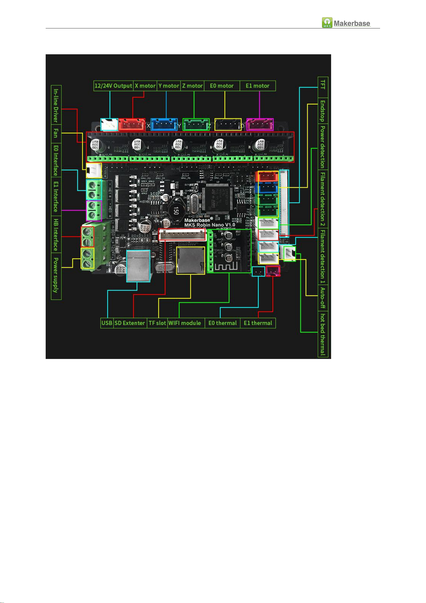
4.1 MKS Robin Nano Front view............................................................................................................................................................. 4
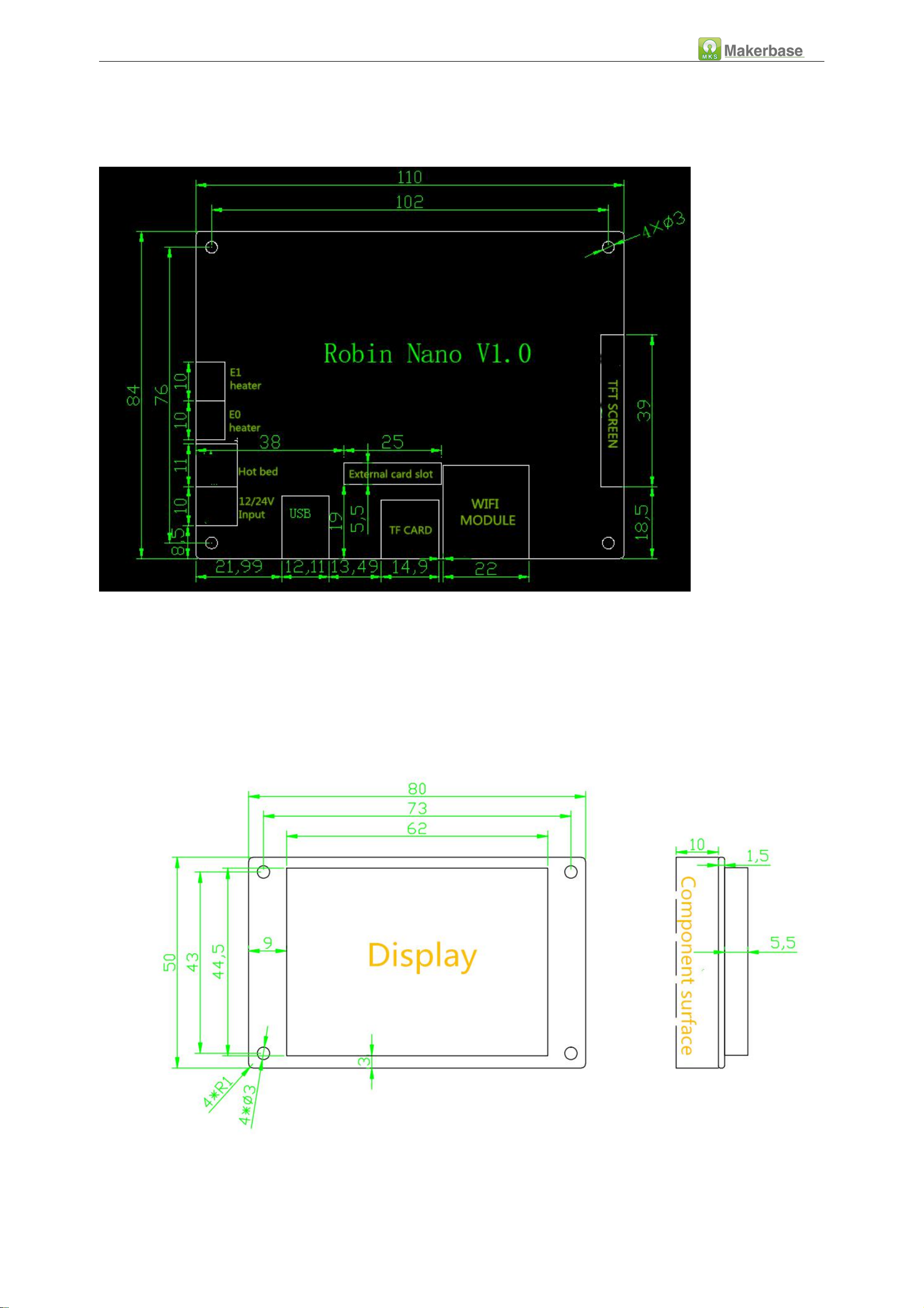
4.2 MKS Robin Nano Installation Dimensional Drawing.........................................................................................................................5
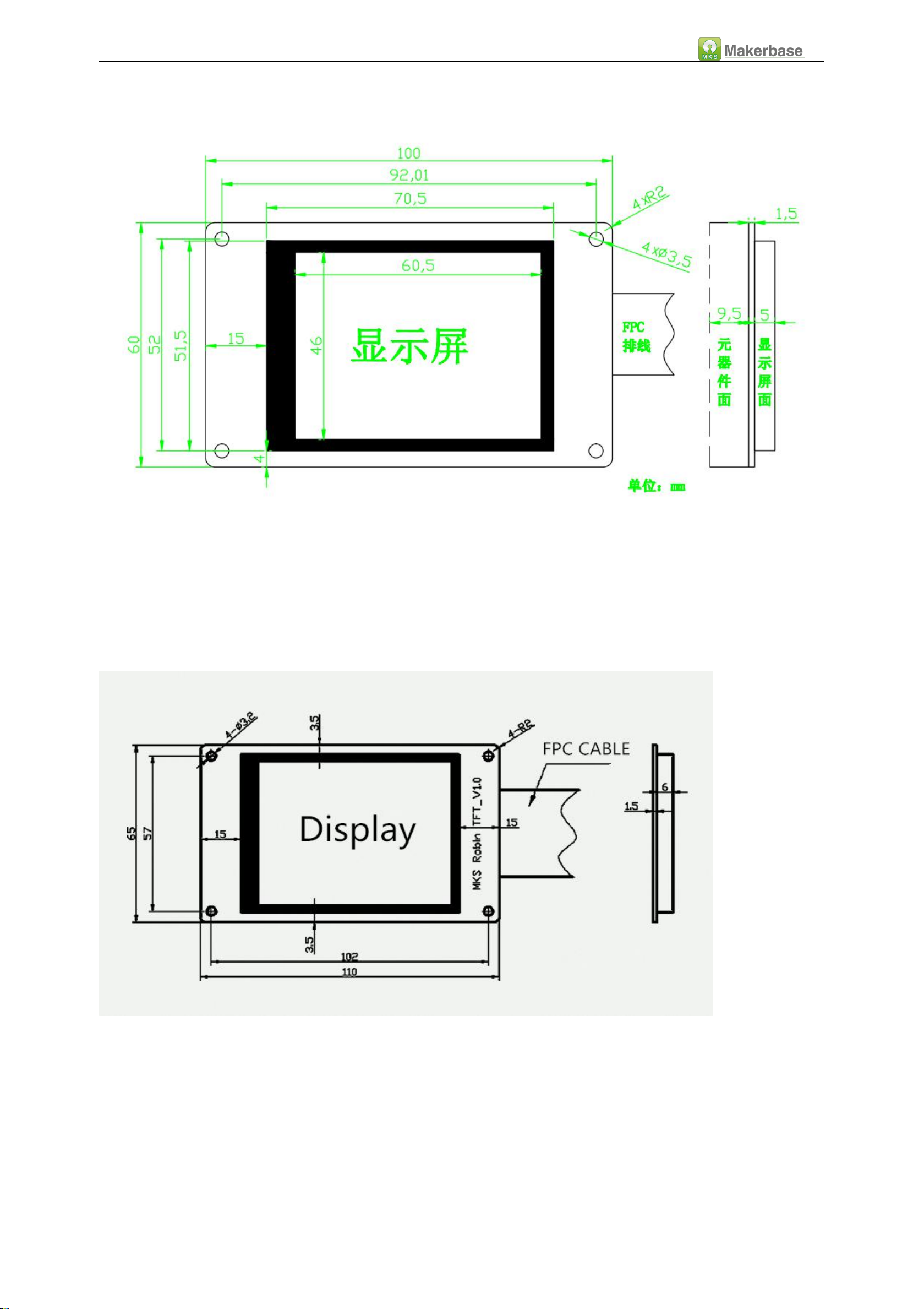
4.3 MKS Robin TFT(2.4inches,2.8inches,3.2inches) Installation Dimensional Drawing.......................................................................... 5
4.4 MKS Robin Nano System connection diagram..................................................................................................................................7
4.5 Driver and motherboard wiring diagram (note the driving direction, do not insert the reverse)........................................................ 8
Ⅴ
.Firmware Upgrade Instructions................................................................................................................................................................11
5.1 The ways to get the MKS Robin Nano Latest Firmware................................................................................................................ 11
5.2 The methods for updating the firmware........................................................................................................................................ 11
Ⅵ
. USB driver Installation.......................................................................................................................................................................... 12
Ⅶ
. Machine parameters and function configuration................................................................................................................................ 13
7.1 Basic settings
(
Important, must be set
)
..................................................................................................................................... 13
7.2 Function setting............................................................................................................................................................................14
7.3 Delta Settings................................................................................................................................................................................. 15
7.4 Bed Leveling Setting....................................................................................................................................................................... 16
7.4.1 Manual leveling....................................................................................................................................................................16
7.4.2 Auto leveling........................................................................................................................................................................ 16
7.5 Filament change function...............................................................................................................................................................17
7.6 Filament Detecting.........................................................................................................................................................................18
7.7 Power off recovery......................................................................................................................................................................... 18
7.8 Auto off after print finish function..................................................................................................................................................19
7.9 Breakpoints recovery......................................................................................................................................................................19
Ⅷ
. The network printing function................................................................................................................................................................. 20
8.1 The introduction of printing mode................................................................................................................................................. 20
8.2 Cloud Print Mode........................................................................................................................................................................... 21
8.3 LAN Print mode.............................................................................................................................................................................. 25
8.4 AP print mode................................................................................................................................................................................ 28
8.5 Model Library Web site..................................................................................................................................................................... 30
Ⅸ
.TFT touch Screen User interface configuration......................................................................................................................................31
9.2 . Steps................................................................................................................................................................................................32
9.3 Name of logo and button picture..................................................................................................................................................... 33
Ⅹ
. Technical Support and Guarantee..........................................................................................................................................................39

2
Ⅰ.Overview
MKS Robin Nano is a product developed by MKS to meet market demand.Configuration of the firmware method
is simpler, and with TFT touch screen(Optional 2.4 inch, 2.8 inch, 3.2 inch when purchased),.Simple operation
interface.The firmware can be easily upgraded through the SD card and the user interface can be customized. It is
suitable for the manufacturer of mass production 3D printers as the main control board.
ⅡFeatures
1.Using 32-bit high-speed ARM chip as the main control chip, using self-developed firmware;
2. Equipped with TFT touch screen (optional 2.4 inches, 2.8 inches, 3.2 inches), simple operation interface and high
sensitivity;
3. Support external high-speed WIFI module, access the cloud, and realize remote printing of cloud model. And
provide Android, IOS system mobile APP, support Chinese and English;
4.AUTO off after finishing can be achieve by the module.
5. Flexible motor drive seat mode, can support 4988, 8825, 2100, 2208 and all kinds of direct plug-in drive, and
support other external drive, to meet your various driving requirements;
6.Upgrade the firmware by SD card, which is easy and convenient to operate;
7. Boot logo and all buttons and other interfaces can be designed by themselves;
8. Support up to 15 custom command button functions;
9. The circuit board is specially designed for heat dissipation, and the heat dissipation effect is better;
10. Using high quality MOSFET tube, the heat dissipation effect is better;
11. Use dedicated power chip to support 12V-24V power input;
12. Can accept 24V input, the same system power can reduce the hot bed current to 1/4, effectively solve the hot
bed MOS tube heating problem;
13. Support breakpoint recovery function, power off save function, filament detection function,auto off after
finishing function;

3
Ⅲ.Motherboard parameters
Board model:
MKS Robin Nano
Microprocessor:
STM32
Size of exterior:
110*84
Mounting hole size:
102*76
Input:
12V~24V 5A~15A
Motor Drive:
4988 ,8825,8729,2208,2100
DRIVE
Temperature sensor:
NTC 100K
、
31855
Touch screen:
2.4 inches ,2.8inches
3.2inches
Print file format:
G-code
Support Machine
Structure:
XYZ
、
delta
、
kossel
、
Ultimaker
、
corexy
Recommended
Software:
Cura
、
Simplify3d
、
Pronterface
、
Repetier-Host
Firmware update:
SD card

4
Ⅳ.Port Instructions
4.1 MKS Robin Nano Front view

5
4.2 MKS Robin Nano Installation Dimensional Drawing
4.3 MKS Robin TFT(2.4inches,2.8inches,3.2inches) Installation Dimensional Drawing
MKS Robin TFT2.4

6
MKS Robin TFT2.8
MKS Robin TFT3.2

7
4.4 MKS Robin Nano System connection diagram

8
4.5 Driver and motherboard wiring diagram (note the driving direction, do not insert the reverse)
The following descriptions and descriptions of the parameters of the different drive modules are limited to the
version produced by the makebase. Different manufacturers may have different
Drive subdivision table: (Motherboard subdivision jumper resistance from left to right are M1, M2, M3, respectively,
where the resistance is High, the resistance is removed to Low, the motherboard defaults M1, M2, M3, are high,
there are other requirements , can adjust itself).
4988Drive subdivision table
8825Drive subdivision table
8729Drive subdivision table
M1
M2
M3
Subdivision
M1
M2
M3
Subdivision
M1
M2
M3
Subdivision
Low
Low
Low
Full Step
Low
Low
Low
Full Step
Lo
w
Low
Low
Full Step
High
Low
Low
1/2 Step
High
Low
Low
1/2 Step
Hig
h
Low
Low
1/2 Step
Low
High
Low
1/4 Step
Low
High
Low
1/4 Step
Lo
w
High
Low
1/4 Step
High
High
Low
1/8 Step
High
High
Low
1/8 Step
Hig
h
High
Low
1/8 Step

9
TMC2208 driver chip internally uses a differential algorithm to extend the 16 subdivisions to 256 subdivisions. The
step values are calculated according to 16 subdivisions.
It is recommended to use 16 subdivisions with a good mute effect. It can also be adjusted according to the
subdivision table according to its own needs.
TMC2100 drive has a clear mute effect and the motor track runs more smoothly. The internal algorithm optimizes
the setting, and the drive subdivision defaults to 16, which is not affected by the transformation of the external
jumper resistance.
Default drive current and maximum current for each drive
High
High
High
1/16 Step
Low
Low
High
1/16 Step
Lo
w
Low
High
1/16 Step
High
Low
High
1/32 Step
Hig
h
Low
High
1/32 Step
Low
High
High
1/32 Step
Lo
w
High
High
1/64 Step
High
High
High
1/32 Step
Hig
h
High
High
1/128 Step
TMC2208 Drive subdivision table(No need to set M3)
M1
M2
Subdivision
high
low
1/2 Step
low
high
1/4 Step
low
low
1/8 Step
high
high
1/16 Step
A4988
DRV8825
LV8729
TMC2208
TMC2100
Default current
1A
1.3A
0.8A
0.707A
0.5A
maximum current
2A
2.5A
1.5A
1.414A
1A

10
The driving current must be converted by measuring the driving voltage. To measure the driving voltage Vref, refer
to the following figure.
The Vref can be adjusted according to the running condition of the motor, and the upper knob can be adjusted by
adjusting (clockwise to increase, counterclockwise to decrease).
Note: Before the adjustment knob, it must be done in the case of power failure. After the adjustment is completed,
the power-on measurement is taken to prevent the drive from burning out.
Formula
I=Vref/0.8
I=Vref*2
I=Vref*2
I=Vref/1.414
I=Vref*1.9/2.5

11
Ⅴ.Firmware Upgrade Instructions
The factory firmware is up to date, so no updates are required.
5.1 The ways to get the MKS Robin Nano Latest Firmware.
Get firmware from customer service or technician
Download the firmware from the makerbase discussion group.
Download on Web:
https://github.com/makerbase-mks?tab=repositories
5.2 The methods for updating the firmware
a. Copy the latest upgrade to the SD card root directory, including:
1
Mks_font
2
Mks_pic
3
Robin_nano.bin
4
Robin_nano_cfg.txt
5
Mkswifi.bin
Attention:Do not modify file names. No need to copy mkswifi.bin without WiFi module
b. Plug the SD card into the motherboard and power on,hear drops ~ ~ A short sound, touch screen display update
process, and so about 30S after the completion of the update.
c. You can click” Settings--about” on the touch screen , to view current firmware information.

12
Ⅵ. USB driver Installation
MKS Robin nano uses CH340 drive. You can get USB driver file with customer service or technician.Click to install the
USB driver file, after the driver installation completes, will connect the Robin motherboard the USB to insert the USB
port.Right-click My Computer, select Device Management, USB port information (figure):

13
Ⅶ. Machine parameters and function configuration
7.1 Basic settings
(
Important, must be set
)
Note: The thermal end interface on the motherboard should be connected to the thermal, otherwise an "error"
prompt will appear.

14
7.2 Function setting

15
A. Motor direction: After the point back 0, if the direction of the reverse direction, then modify 1 or 0;
B. Pulse value
:
The pulse value of 1mm for each axis is calculated, and the formula for calculating the pulse value of
each shaft motor is as follows:
Formula of pulse number/mm of synchronous wheel motor:
(
360÷step angle
)
×Subdivision÷
(
Diameter×3.14
)
The formula of the pulse number/mm of The screw rod Motor:
(
360÷step angle
)
×Subdivision÷lead
C. endstops type: The endstop switch is divided into two types: normally open and normally closed, 1 is normally
open and 0 is normally closed;
D. Enable the endstop of each axis: the endstop switch triggered when returning to zero, generally XYZ is the
minimum limit, and delta is the maximum limit;
E. Enable the software limit of each axis: the maximum travel set in the configuration file, the maximum travel
cannot be exceeded when moving.
F. Homing direction: Set according to where the machine's endstop switch is installed on the machine. For example,
the endstop switch of the x-axis is placed on the left side of the x-axis, then the homing direction is the minimum
value returning to zero.
7.3 Delta Settings
The parameter corresponding to the serial number in the picture
(1). >DELTA_PRINTABLE_RADIUS
(2).>DELTA_DIAGONAL_ROD
(3).>DELTA_EFFECTOR_OFFSET
(4).>DELTA_CARRIAGE_OFFSET
(5).>DELTA_RADIUS

16
7.4 Bed Leveling Setting
types of leveling: manual leveling and automatic leveling
7.4.1 Manual leveling
7.4.2 Auto leveling

17
7.5 Filament change function
Filament change function: It is convenient for you to replace the consumables. You can also use the refueling
function to configure the reversing head rotation speed and the minimum temperature in the configuration file
during the printing midpoint pause, as shown below;
Table of contents
Other MKS Motherboard manuals
Popular Motherboard manuals by other brands

NXP Semiconductors
NXP Semiconductors KITFS26AEEVM user manual

ASROCK
ASROCK IMB-130 Jumpers and headers setting guide

Asus
Asus P5KPL-AM - SE Motherboard And Intel Core 2... user manual

Microchip Technology
Microchip Technology EVK-UTC2000 user guide

Biostar
Biostar M6VLQ Grand manual

Analog Devices
Analog Devices DC2904A-B user guide