BlueChip RE3 User manual

Page | 1
RE3
Single Board Computer
User Guide
Document Reference: RE3 User Guide
Document Issue: 1.3

RE3 Table Of Contents
Page | 2
Contents
Copyright............................................................................................................................................................4
Limitations of Liability.......................................................................................................................................4
Trademarks.........................................................................................................................................................4
Regulatory Statements........................................................................................................................................5
Safety Warning for North America ....................................................................................................................5
Manual Organisation ..............................................................................................................................................6
Introduction ............................................................................................................................................................7
Functional Overview ..........................................................................................................................................8
Specification.......................................................................................................................................................9
General Precautions..............................................................................................................................................10
Electro-Static Discharges..................................................................................................................................10
On-Board Battery .............................................................................................................................................10
Electromagnetic Compatibility.........................................................................................................................10
Mechanical Specifications....................................................................................................................................12
Connector Locations.............................................................................................................................................13
Connector Details .............................................................................................................................................14
P1 –Ethernet Connector...............................................................................................................................14
P2 –Dual USB Connector (Edge of Board).................................................................................................14
P25, P26, P27 –USB Device........................................................................................................................14
P4/P15 –Power in Connector.......................................................................................................................14
P5 –Audio Connector ..................................................................................................................................15
P6 –GPIO Connector...................................................................................................................................15
P7 –Utilities Connector................................................................................................................................17
P10 –RS232 Full Connector ........................................................................................................................17
P11 –RS232 & RS422/485 Connector.........................................................................................................17
P8 –Video Connector...................................................................................................................................18
P30 –Fan Connector ....................................................................................................................................19
P20/P21 –Camera Input...............................................................................................................................19
RTC Battery..................................................................................................................................................19
Thermal Considerations........................................................................................................................................21
RE3 Heatsink................................................................................................................................................21
System Software...................................................................................................................................................22
Operating Systems Supported...........................................................................................................................22
General Purpose I/O .........................................................................................................................................22
SYSFS ..........................................................................................................................................................22
GPIO Mapping for RE3................................................................................................................................22
Bootloader Firmware........................................................................................................................................23
Maintenance .........................................................................................................................................................24
Amendment History .............................................................................................................................................24

RE3 Table Of Contents
Page | 3
Cable Options.......................................................................................................................................................25
Audio P7 –BCT p/n 1371-1421...................................................................................................................25
GPIO P6 –BCT p/n 1371-1422....................................................................................................................25
Utility P7 –BCT p/n 1371-1423...................................................................................................................26
RS232 P10 –BCT p/n 1371-1425................................................................................................................26
RS232/422/485 P11 –BCT p/n 1371-1426..................................................................................................27
Camera In .....................................................................................................................................................27
LCD Options ........................................................................................................................................................28

RE3 Introduction
Page | 4
Copyright
All rights reserved. No part of this publication may be reproduced, stored in any retrieval system, or transmitted,
in any form or by any means, electronic, mechanical, photocopied, recorded or otherwise, without the prior
permission, in writing, from the publisher. For permission in the UK please contact Blue Chip Technology.
Information offered in this manual is believed to be correct at the time of printing. Blue Chip Technology
accepts no responsibility for any inaccuracies. The information contained herein is subject to change without
notice. There are no express or implied licences granted herein to any intellectual property rights of Blue Chip
Technology Ltd.
Limitations of Liability
In no event shall Blue Chip Technology be held liable for any loss, expenses or damages of any kind
whatsoever, whether direct, indirect, incidental or consequential, arising from the design or use of this product
or the support materials supplied with this product. If this product proves to be defective, Blue Chip Technology
is only obliged to replace or refund the purchase price at Blue Chip Technology's discretion according to their
Terms and Conditions of Sale.
Trademarks
All trademarks and registered names acknowledged.
IBM, PC, AT and PS/2 are trademarks of International Business Machines Corporation (IBM).
AMD is a registered trademark of Advanced Micro Devices Inc.
MSDOS and WINDOWS are registered trademarks of the Microsoft Corporation.

RE3 Introduction
Page | 5
Regulatory Statements
CE
This product has been designed and assessed to meet the essential protection requirements of the European
EMC Directive (2004/108/EC), the Low Voltage Directive (2006/95/EC), and the R&TTE Directive
(1999/5/EC) when installed and used in conjunction with the guidelines provided within this document.
[Note that compliance with the R&TTE directive is only required for those versions of the product equipped
with radio frequency interfaces].
FCC
NOTE:
FCC compliance of product versions equipped with radio frequency interfaces may require specific approval for
the finished products.
WARNING:
Changes or modifications not expressly approved by the manufacturer could void the user's authority to operate
the equipment.
Safety Warning for North America
If the power lead (cord) is not supplied with the computer, select a power lead according to your local electrical
regulations. In the USA use a 'UL listed' lead. In Canada use a CSA approved or 'cUL listed' lead.
Si le cordon secteur n'est pas livré avec l'ordinateur, utiliser un cordon secteur en accord avec votre code
electrique nationale. En l'Etat Unis utiliser un cordon secteur 'UL listed'. En Canada utiliser un cordon secteur
certifié CSA, ou 'cUL listed'.

RE3 User Guide Organisation
Page | 6
Manual Organisation
This manual describes in detail the RE3 Product range.
We have tried to include as much information as possible but we have not duplicated information that is
provided in the standard Technical References, unless it proved to be necessary to aid in the understanding of
the product.
The manual is sectioned as follows:
Introduction;
Overviews, showing outline dimensions;
Layout, showing where the various connectors are located, and their pin-out details;
Firmware Setup
Maintenance details
We strongly recommend that you study this manual carefully before attempting to interface with the RE3 or
change the standard configurations. Whilst all the necessary information is available in this manual we would
recommend that unless you are confident, you contact your supplier for guidance.
IT IS PARTICULARLY IMPORTANT THAT YOU READ THE SECTION 'PRECAUTIONS' BEFORE
HANDLING ANY COMPONENTS INSIDE THE UNIT.
If you have any suggestions or find any errors concerning this manual and want to inform us of these, please
contact our Technical Services department with the relevant details.

RE3 Product Summary
Page | 7
Introduction
The Blue Chip Technology RE3 (BCT-RE3) is the next step in the highly successful RE range of all in one
compact computers.
The BCT-RE3 has multiple CPU options, 1GHz Dual Core and 1GHz Quad Core. Both options are available as
extended temperature product. All RE3s are supplied with 1GB of DDR3 Memory and 1GB of NAND Flash.
Further, additional NAND Flash can be added through an optional μSD Card.
The BCT-RE3 can operate from 7V DC input through to 36V DC input. Power requirements will vary
depending on any LCD panel and other peripherals attached to the RE3.
For example with the Dual 1GHz BCT-RE3 with the U.R.T. UMSH-8173MD-1T 5.7” Combined LCD and
Touch Screen, the operational power requirements will vary between 5.6W for Linux Linaro, at the desktop, up
to 13.5W with applications running CPU, GPU and VDU heavily. Attaching peripherals such as USB will
increase this further.
On its own, the RE3 operates at approximately 3.5/3.6W Dual/Quad CPU without power saving and without
applications running.
The BCT-RE3 has the capability to support a Lithium Battery via connector P14 to retain time and date when
the unit is powered off. Please refer to RTC Battery section for options on using this feature

RE3 Overview
Page | 8
Functional Overview
The following block diagrams show the I/O and Power Management for the RE3

RE3 Overview
Page | 9
Specification
•Dual or Quad Cortex A9 CPU
•1GB DDR3 Memory soldered onboard
•1GB NAND Flash soldered onboard
•Optional μSD Card NAND Flash Storage
•SATA 3Gbit Socket
•H.264 1080p60 decode, 1080p30 encode and 3-D video playback in HD
•Triple Graphics system with a Quad shader 3D unit capable of 200MT/s, separate OpenVG Vertex
acceleration engine
•Two independent video outputs –HDMI and 24 bit LCD
•10/1001000 Mbit Ethernet including magnetics
•Five USB 2.0 Hosts [ four type A and one header ]
•Single USB 2.0 Device
•Dual RS-232 (1 Full, 1 2-wire)
•Single RS422/485
•Stereo Audio Inputs & Stereo Outputs plus Microphone In
•Battery backed Real-Time Clock
•12 GPIO lines
•One CAN 2.0 interface
•Utilities connector
•Wide Input Voltage –7 to 36 volts
o5V Rail for USB etc limited to 2A draw
o3.3V for GPIO (if connected) is limited to 2.2A
•power consumption –typically 5.0/5.5 watts Dual/Quad (LCD not included) running application
•Two Camera inputs on UFL connectors
oSupports NTSC M, NTSC J, NTSC 4.43, PAL B/G/H/I/D, PAL M, PAL N, PAL 60
o10-bit 4x Oversampling (54Msos) ADC with true 10-bit Digital Processing
•Mini PCIe socket supporting
o2G/3G Modem, GPS, Wi-Fi, Bluetooth

RE3 Precautions
Page | 10
General Precautions
Your Single Board Computer is susceptible to damage by electrostatic discharges. In order to avoid damage,
you should work at an anti-static bench and observe normal anti-static precautions. Wear an anti-static wrist
strap connected to an earth point before opening any packaging.
Where a wrist strap is not available, discharge any static charge you may have built-up by touching an earth
point. Avoid any further movement that could build up another static charge. Touch an earth point from time to
time to avoid further build-up, and remove the items from their anti-static bags only when required
Electro-Static Discharges
It is important to realise that the components on the RE3 can be damaged by static electricity. Bear in mind that
the damage caused by static electricity may vary from total destruction to partial damage, which may not be
immediately obvious. This could have an effect on the product’s reliability and warranty. Before handling the
RE3, ensure that you take necessary static precautions. Ideally you should work at an anti-static bench and wear
an approved wrist strap or if that is not possible, touch a suitable ground to discharge any static build up before
touching the electronics. This should be repeated if the handling continues for any length of time.
If it is necessary to move the RE3 around, place it into an anti-static bag. This will prevent any static electricity
build up damaging the board. Metallised bags are preferred. Do not use black anti-static bags for any item
containing a battery because these tend to be conductive and will discharge the battery.
On-Board Battery
The processor board can be fitted with a Lithium battery. Great care should be taken with this type of battery. If
the battery is mistreated in any way there is a very real possibility of fire, explosion, and personal harm. Under
NO circumstances should it be short-circuited, exposed to temperatures in excess of 100°C or burnt, immersed
in water, recharged or disassembled.
Expired batteries remain hazardous and must be disposed of in a safe manner, according to local regulations.
Le panneau de processeur est équipé d’une batterie de lithium. Le grand soin devrait être pris avec ce type de
batterie. Si la batterie est mistreated il y a de dans de toute façon un possibility très vrai du feu, d’expolosion et
de mal personnel. Dans au cunes circonstances il est sous peu circuité, exposé aux températures au dessus de
100 degrés de centrigrade ou brûlé, immergé dans l’eau, rechargée ou dissassambled.
Les batteries expirées restent dazaedous et doivent être reejetées d’une façon sûre, selon des règlements locaux.
Electromagnetic Compatibility
This product has been assessed operating in representative, standard configurations. As with any PC product,
however, final installation & configuration can vary significantly, and so the following guidelines are offered to
help ensure that compatibility is maintained.
All components added to a system should either carry appropriate equivalent levels of compliance, or
be tested for compliance as part of the final system, and should be installed in accordance with supplier
recommendations.
The external enclosure should be securely fastened (with standard lids and covers in place) to ensure
good metal-to-metal contact around the internal electronics

RE3 Precautions
Page | 11
Any metal back plate must be securely screwed to the chassis of the computer to ensure good metal-to-
metal (i.e. earth) contact.
Metal, screened, connector bodies should be securely connected to the enclosure.
The external cabling to boards causes most EMC problems. It is recommended that any external
cabling to the board be totally screened, and that the screen of the cable connects to the metal end
bracket of the board or the enclosure and hence to earth. Round, screened cables with a braided wire
screen are used in preference to those with a foil screen and drain wire. Wherever possible, use metal
connector shells that connect around the full circumference of the cable screen: they are far superior to
those that earth the screen by a simple “pig-tail”.
The keyboard and mouse will play an important part in the compatibility of the processor card since
they are ports into the board. Similarly, they will affect the compatibility of the complete system. Fully
compatible peripherals must be used otherwise the complete system could be degraded. They may
radiate or behave as if keys/buttons are pressed when subject to interference. Under these
circumstances it may be beneficial to add a ferrite clamp on the leads as close as possible to the
connector. A suitable type is the Chomerics type H8FE-1004-AS.
USB cables should be high quality screened types.
Ensure that the screens of any external cables are bonded to a good RF earth at the remote end of the
cable.
Failure to observe these recommendations may invalidate the EMC compliance
RE3 Installation
Page | 12
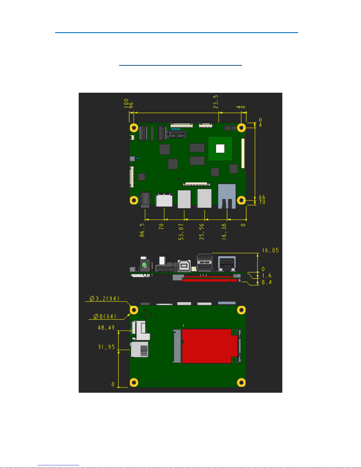
Mechanical Specifications
Outline Dimensions
RE3 Installation
Page | 13
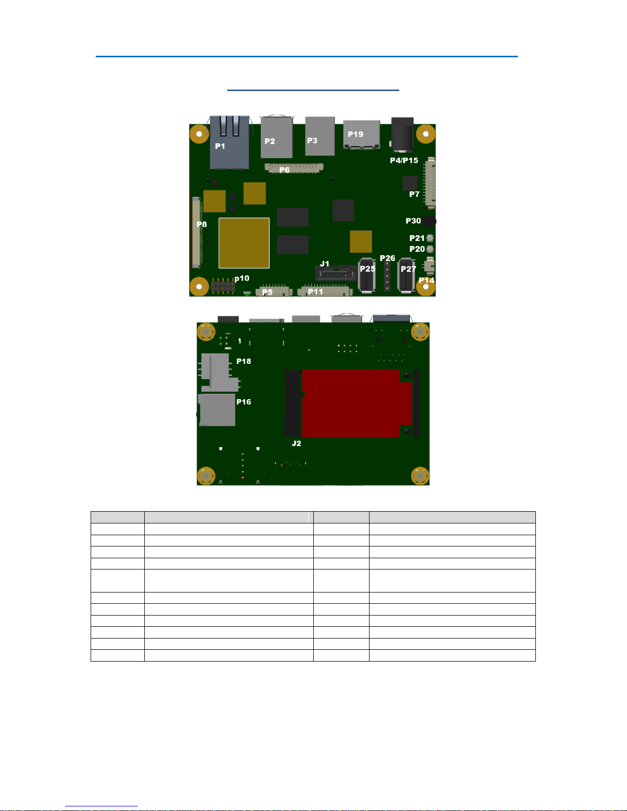
Connector Locations
Connector
Description
Connector
Description
P1
RJ45 Ethernet
P2
USB-A x 2
P3
0USB-B
P4 / P15
Power Input
P5
Audio
P6
GPIO
P7
Utilities
P8
LCD Video
P10
RS232 (COM3)
P11
RS232 (COM2) and
RS422/485(COM1)
P14
Battery
P16
uSD
P18
SIM Socket
P20
Camera Input #1
P21
Camera Input #2
P25
USB
P26
USB
P27
USB
P30
Fan Connector
J1
SATA
J2
Mini PCI Express
Note: Not all connectors may be fitted
COM2 is a 2 wire device
RE3 Installation
Page | 14
Connector Details
P1 –Ethernet Connector
Pin
Signal
External Connections
(RJ45)
Comments
1
TD+
1
Transit Data +ve
2
TD-
2
Transit Data –ve
3
CTT
-
Centre Tap Transmit
4
Ground
-
Electrical Ground
5
Ground
-
Electrical Ground
6
CTR
-
Centre Tap Receive
7
RD+
3
Receive Data +ve
8
RD-
6
Receive Data –ve
9
VCC3
-
Pull up to 3.3 volt VCC
10
LNK/#ACT
-
Link/Activity LED
11
SPD100#
-
Speed LED
12
VCC3
-
Pull up to 3.3 volt VCC
13
Ground
-
Electrical Ground
14
Ground
-
Electrical Ground
P2 –Dual USB Connector (Edge of Board)
Pin
Signal
Comments
1
VBUS
+5 volts –Filtered & current limited
2
D1-
USB 1 Data Negative
3
D1+
USB 1 Data Positive
4
Ground
Filtered Electrical ground
5
VBUS
+5 volts –Filtered & current limited
6
D2-
USB 2 Data Negative
7
D2+
USB 2 Data Positive
8
Ground
Filtered Electrical ground
P25, P26, P27 –USB Device
Pin
Signal
Comments
1
VBUS
+5 volts –Filtered & current limited
2
D-
USB 1 Data Negative
3
D+
USB 1 Data Positive
4
Ground
Filtered Electrical ground
P4/P15 –Power in Connector
The RE3 has the option to be powered from either a 2.5/5.5mm Power Jack (P4) or a 2 Pin Screw Terminal
(P15)
P15
Pin 1
Ground
Pin 2
Vcc

RE3 Installation
Page | 15
P5 –Audio Connector
Pin
Signal
Comments
1
Line Out Right
Audio Output Right Channel
2
Line Out Left
Audio Output Left Channel
3
Audio Ground
Audio Ground
4
Line In Left
Audio In Left Channel
5
Line In Right
Audio In Right Channel
6
Audio Ground
Audio Ground
7
Audio Ground
Audio Ground
8
Microphone IN
Mono Audio Input
P6 –GPIO Connector
The GPIO interface is a flexible, logic-level port providing a mix of dynamically-configured hardware inputs
and outputs. It is designed for use within a chassis with localised electronics. Interfacing to signals which may
pick up noise transients will require buffering and/or conditioning circuits.
Pin
Signal
Comments
1
VCC_GPIO
Reference supply input
2
GPIO 1
Input/output
3
GPIO 2
Input/output
4
GPIO 3
Input/output
5
GPIO 4
Input/output
6
GPIO 5
Input/output
7
GPIO 6
Input/output
8
GPIO 7
Input/output
9
GPIO 8
Input/output
10
GPIO 9
Input/output
11
GPIO 10
Input/output
12
GPIO 11
Input/output
13
CANH
CAN High
14
CANL
CAN Low
15
0V_GPIO
Tied to RE3 circuit ground
The GPIO outputs are designed for flexibility, and will interface to electronics operating with signal levels
between 2.3V & 5.5V DC. The function and direction of the GPIO signals is configured by RE3 software (see
the software manuals for details of GPIO port mappings and configuration).

RE3 Installation
Page | 16
Basic electrical characteristics are as follows:-
Feature:
Pin(s):
Min:
Max:
Units:
VCC_GPIO Supply Voltage
VCC_GPIO
2.3
5.5
V
VIH Input High Voltage
GPIO 1 .. GPIO 11
VCC_GPIO –0.4
VCC_GPIO
V
VIL Input Low Voltage
GPIO 1 .. GPIO 11
0
0.15
V
VOH Output High Voltage
GPIO 1 .. GPIO 11
VCC_GPIO * 0.67
-
V
VOL Output Low Voltage
GPIO 1 .. GPIO 11
-
0.4
V
ICC Supply Current
VCC_GPIO
-
12
µA
Quiescent output current in the high state appears equivalent to a 10K pull-up (short-duration current boosting is
applied, however, during signal transitions to speed up rise/fall times). Optimum performance is achieved with
short cable connections, and minimum capacitive loading on the signal lines.
GPIO VCC
The RE3 provides for the option to provide VCC from the RE3 itself via a solder link LK5.
In order to convert the RE3 to provide GPIO VCC, it is necessary to solder a link across two pads as shown

RE3 Installation
Page | 17
P7 –Utilities Connector
Power
Wake
1
Power_Off#
8
Wake# / SLEEP_RQ#
2
Ground
9
Ground
Reset
Battery
3
Reset#
10
VBAT
4
Ground
11
Ground
Serial Bus
Setup
5
Serial Clock
12
Boot MODE#
6
Serial Data
13
Ground
7
Ground
P10 –RS232 Full Connector
Pin
Signal
Comments
1
XDCD3#
COM 3 Data Carrier Detect
2
XRX3
COM 3 RX
3
XTX3
COM 3 TX
4
XDTR3#
COM 3 Data Terminal Ready
5
0 volts
Electrical ground
6
XDSR3#
COM 3 Data Send Ready
7
XRTS3#
COM 3 Ready To Send
8
XCTS3#
COM 3 Clear to Send
9
XRI#
COM 3 Ring indicator
10
+5 volts
Fused voltage rail
P11 –RS232 & RS422/485 Connector
Pin
Signal
Comments
1
0 volts
Electrical ground
2
RS232 RX
COM 2
3
RS232 TX
COM 2
4
+5 volts
Fused voltage rail
5
0 volts
Through 10K pull down
6
VCC
Through 10K pull up
7
Termination
120R + 100nF link to pin 10
8
CRX1N
9
CRX1N
Same signal as pin 8
10
CRX1P
11
CTX1N
12
CTX1P
With COM1 RS422/RS485 operation in a multi drop network, the Transmit Line is only enabled when the DTR
line is enabled. Refer to the CE 6 User guide for more details

RE3 Installation
Page | 18
P8 –Video Connector
Mating Part FFC 0.5mm Pitch 50Way
Pin
Signal
Comments
1
0 volts
Electrical ground
2
XL
Touchscreen Data
3
YD
Touchscreen Data
4
XR
Touchscreen Data
5
YU
Touchscreen Data
6
0 volts
Electrical ground
7
LCD_PWM2
PWM Brightness Control 2
8
LCD_PWM1
PWM Brightness Control 1
9
0 volts
Electrical ground
10
SDA
I2C Data
11
SCL
I2C Clock
12
0 volts
Electrical ground
13
D0
Blue 0
14
D1
Blue 1
15
D2
Blue 2
16
D3
Blue 3
17
D4
Blue 4
18
D5
Blue 5
19
D6
Blue 6
20
D7
Blue 7
21
0 volts
Electrical ground
22
D8
Green 0
23
D9
Green 1
24
D10
Green 2
25
D11
Green 3
26
D12
Green 4
27
D13
Green 5
28
D14
Green 6
29
D15
Green 7
30
0 volts
Electrical ground
31
D16
Red 0
32
D17
Red 1
33
D18
Red 2
34
D19
Red 3
35
D20
Red 4
36
D21
Red 5
37
D22
Red 6
38
D23
Red 7
39
0 volts
Electrical ground
40
VSYNC
First line Marker
41
HSYNC
Line Pulse
42
ACBIAS
Display Enable
43
0 volts
Electrical ground
44
PCLK
Pixel clock
45
EN_PANL
Enable Panel
46
EN_LITE
Enable Backlight
47
0 volts
Electrical ground
48
NC
No Connection
49
VIN
Raw Power input
50
VIN
Raw Power input

RE3 Installation
Page | 19
P30 –Fan Connector
Mating part is Molex 87439-0200 1.5mm PICO-SPOX
P30
Pin 1
Vcc_5V
Pin 2
Ground/ FanPWM
Pin 2 is switched ground with a flyback diode incorporated, to absorb the back EMF from a fan motor. The
output can be operated as a digital output (high or low) or as a PWM signal. The fan is driven from the PIC
microcontroller, by sending an I2C command from the i.MX6 to the PIC.
Command code 0x09 sets the fan speed with a single byte parameter. 0 = OFF, 255 = ON, 1-254 = PWM
Command code 0x0a returns the current fan speed.
Example - turn fan on
i2cset -y -f 2 0x56 9 0xFF
Example - turn fan off
i2cset -y -f 2 0x56 9 0
P20/P21 –Camera Input
Mating part is ufl
P20 / P21
Pin 1
Antenna
Pin 2, 3
Ground
RTC Battery
The RM3 provides a real-time clock (RTC) that can preserve the time when main power is off, by adding a
backup battery.
This section describes the options for using this feature.
Battery specification
The battery supply is provided to the RM3 through the VBATT connection (J4, pin 56).
The battery voltage needs to be in the range 3.6V to 3.0V and therefore a Lithium - manganese dioxide "Li-Mn"
battery like a CR2032 can be used.
The RM3 does not offer the ability to charge a battery or super-capacitor, so rechargeable lithium batteries are
not suitable.
Current consumption
The RTC is part of the SNVS block on the i.MX6, which also includes other logic and non-volatile storage. As a
result, the current consumption (max. 275uA) is considerably higher than might be expected for a RTC alone.
No current is drawn from the VBATT supply when the main RM3 power is on.

RE3 Installation
Page | 20
Applications
The relatively high battery current consumption may be important depending on the application.
When using a CR2032 battery, a simple calculation shows that the RTC may be able to hold up for around 34
days without the main power:
Based on CR2032 typical capacity of 225mAh
225mAh / 275uA = 818h
818/24 = 34.09 days
This might not be suitable for some applications, if main power is unavailable frequently or for long periods. In
such cases, we recommend the use of a separate RTC on the host board, such as DS1339
http://www.maximintegrated.com/en/products/digital/real-time-clocks/DS1339U.html
This device has a typical backup current consumption of less than 1uA and should last for several years with a
CR2032 battery (using the same calculation as above). It also has a built-in charging circuit, and can be used
with a rechargeable battery or a super capacitor.
When using a separate RTC on the host board, the RM3 VBATT signal can be left unconnected.
Table of contents
Other BlueChip Motherboard manuals


 Easy installation guide")