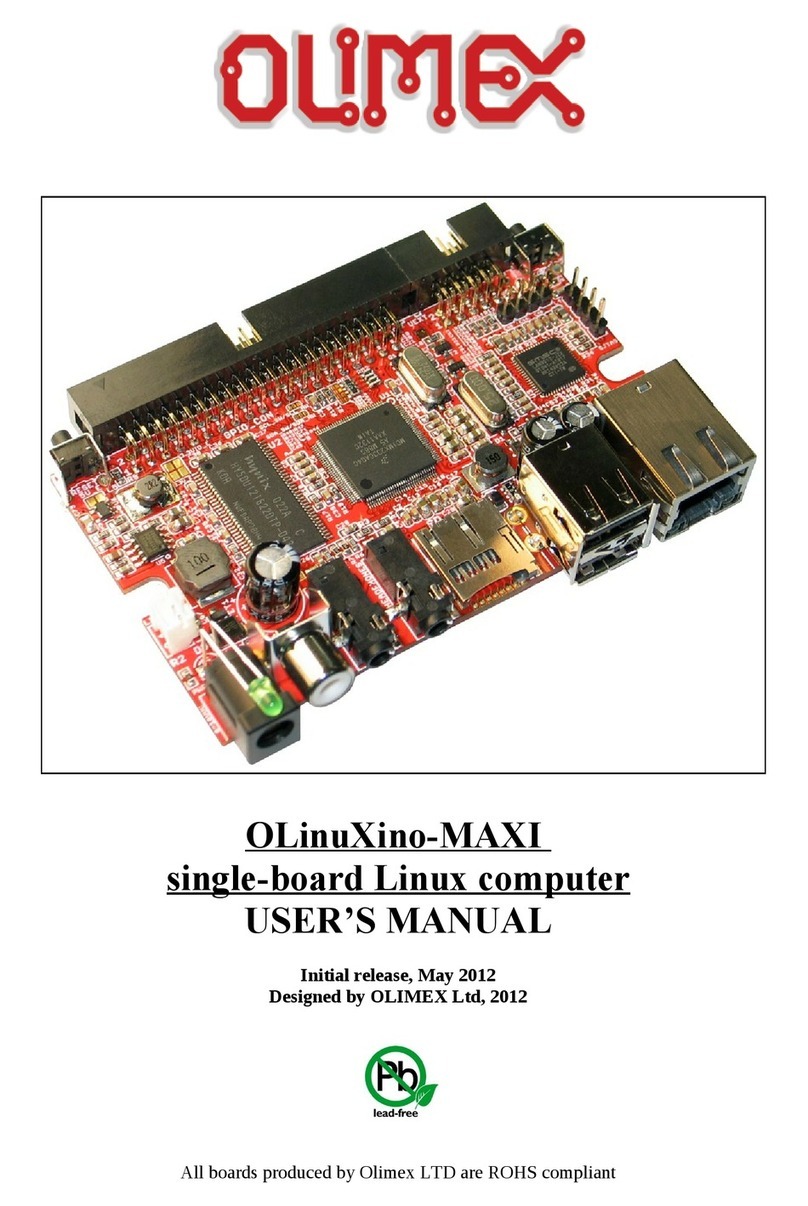
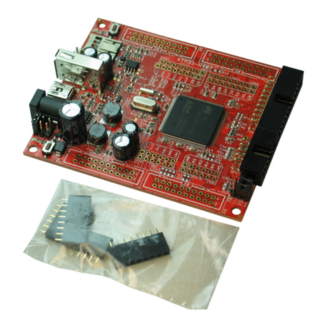
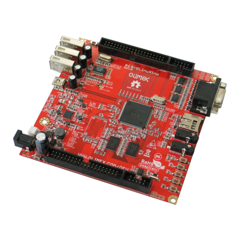
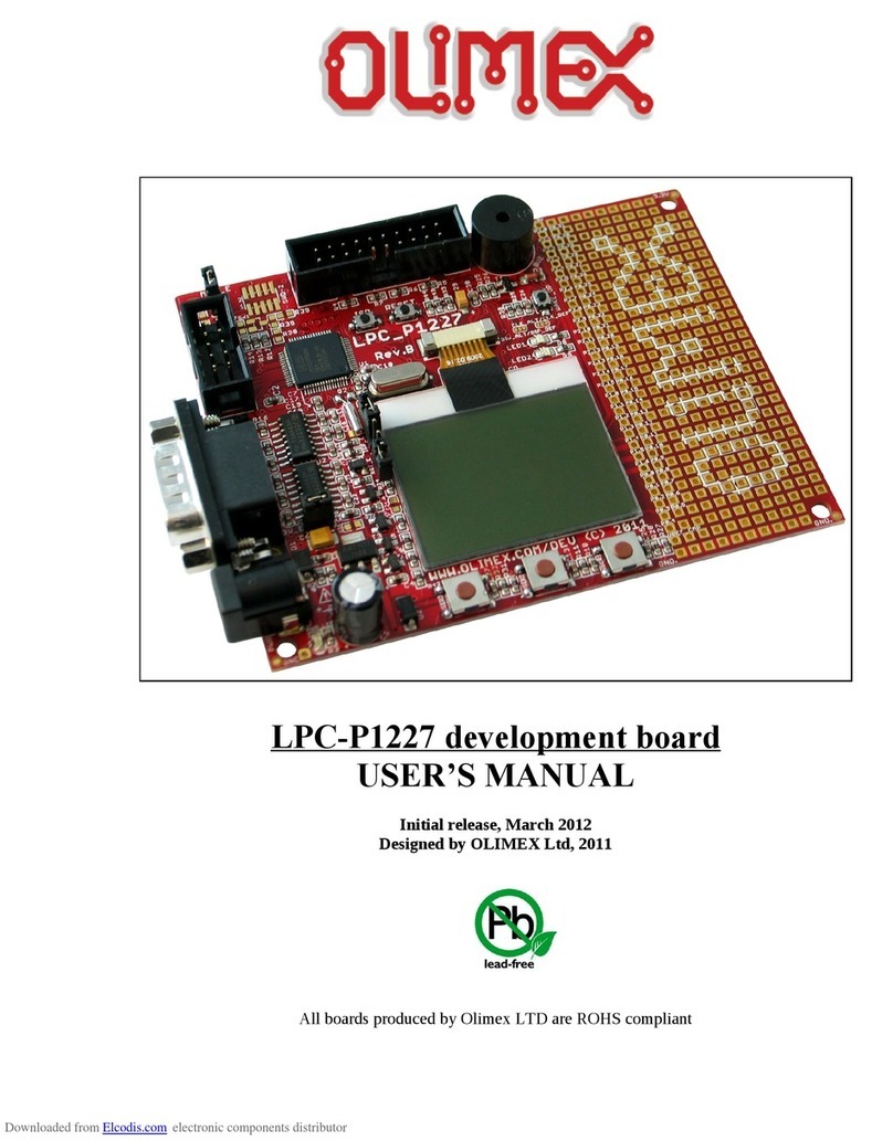
OLIMEX© 018 STM3 -H407 user's manual
Table of Contents
D SCLA MER ............................................................................................................. 2
CHAPTER 1 OVERV EW ......................................................................................... 5
1. Introduction to the chapter ....................................................................................................... 5
1.1 Features ..................................................................................................................................... 5
1.2 H407 or E407? .......................................................................................................................... 6
1.3 arget market and purpose of the board ............................................................................... 6
1.4 Organization ............................................................................................................................. 6
CHAPTER 2 SETT NG UP THE STM32-H407 BOARD ....................................... 7
2. Introduction to the chapter ....................................................................................................... 7
2.1 Electrostatic warning ............................................................................................................... 7
2.2 Requirements ........................................................................................................................... 7
2.3 Powering the board .................................................................................................................. 8
2.4 Prebuilt software ...................................................................................................................... 8
CHAPTER 3 STM32-H407 BOARD DESCR PT ON ............................................ 9
3. Introduction to the chapter ....................................................................................................... 9
3.1 Layout (top view) ..................................................................................................................... 9
3.2 Layout (bottom view) ............................................................................................................. 10
CHAPTER 4 THE STM32F407ZGT6 M CROCONTROLLER ......................... 11
4. Introduction to the chapter ..................................................................................................... 11
4.1 he S M32F407ZG 6 features ............................................................................................ 11
CHAPTER 5 CONTROL C RCU TY AND HARDWARE MODULES ............. 13
5. Introduction to the chapter ..................................................................................................... 13
5.1 Reset ........................................................................................................................................ 13
5.2 Clocks ...................................................................................................................................... 13
5.3 Power supply circuit .............................................................................................................. 13
CHAPTER 6 CONNECTORS AND P NOUT ....................................................... 14
6. Introduction to the chapter ..................................................................................................... 14
6.1 J AG/SWD debug ................................................................................................................. 14
6.2 SD/MMC slot .......................................................................................................................... 15
6.3 UEX module ......................................................................................................................... 15
6.4 USB HOS .............................................................................................................................. 16
6.5 USB_O G ............................................................................................................................... 16
6.6 Arduino platform ................................................................................................................... 16
6.7 20-pin connectors – PD – PE – PF – PG .............................................................................. 18
6.8 PWR Jack ............................................................................................................................... 19
6.9 Battery connector ................................................................................................................... 19
6.10 U3BOO ............................................................................................................................... 19
Page 3 of 30
