Bluerock Tools CG-211Y Quick start guide

OPERATIONAL MANUAL
MODEL: CG-211YPIPE TORCH/BURNER MACHINE
by BLUEROCK ® Tools
Volume
1.1

MWS-CG-211Y TORCH BURNER MACHINE
UNPACKING THE ITEM
Caution: This machine is packed together with items that may be sharp, oily and overly heavy objects.
Remove the machine from the packaging in a safe manner. Check to ensure all accessories are included with
the item while unpacking. If any parts are found to be missing, contact the retailer as soon as possible. Do
not throw away the packaging until the item is out of the guarantee period. Dispose of the packaging in an
environmentally responsible manner. Recycle if possible. Keep all plastic bags away from children due to
risk of suffocation.
©THE NEWMAN TRADING COMPANY LLC DBA BLUEROCK® TOOLS 2016
1100 SW 16th St • Suite D
Renton, WA 98057
Phone 206.604.8363 • Fax 425.572.5167
www.bluerocktools.com

CG-211Y TORCH BURNER MACHINE
Table&of&Contents&
SAFETY' 1!
PRE-OPERATIONAL SAFETY CHECKS! 1!
OPERATIONAL SAFETY CHECKS! 1!
SPECIFICATIONS' 3!
INCLUDED'ACCESSORIES' 3!
ADDITIONAL ACCESSORIES FOR THIS MACHINE CAN BE FOUND IN BLUEROCK ®TOOLS ONLINE SHOP AT
WWW.BLUEROCKTOOLS.COM OR FROM YOUR LOCAL RETAILER.! 3!
CUTTING'TIP'SPECIFICATIONS' 4!
OPERATIONS' 5!
PURPOSE! 5!
OPERATIONAL PRINCIPLES! 5!
MACHINE COMPONENTS! 5!
SETTING UP THE MACHINE! 6!
TRANSPORTING THE MACHINE! 7!
RUNNING THE MACHINE! 8!
PROPER LIGHTING OF GAS TORCH!10!
TROUBLESHOOTING'12!
GENERAL'MAINTENANCE'13!

CG-211Y TORCH BURNER MACHINE
1
Safety
DO NOT USE THIS MACHINE UNLESS YOU HAVE READ THE
OPERATING INSTRUCTIONS!
Welding safety glasses must be worn at
all times in work areas.
Long and loose hair must be
contained.
Appropriate steel toe footwear must be
worn.
Close fitting/protective leather
clothing must be worn.
Leather safety gloves should be worn at
all times and jewelry must not be worn.
Hearing protection should be
worn when using this machine.
Hard-hat must be worn while using
machine.
Dust/fume mask must be worn
while using this machine.
Read operational manual prior to use.
PRE-OPERATIONAL SAFETY CHECKS
ØExamine the body of the machine and inspect for damage or defects.
ØExamine the body and hoses of the cutting assembly.
ØExamine the cutting torch tips and torch barrel inside and out for damage and/or defect.
OPERATIONAL SAFETY CHECKS
ØONLY to be operated by qualified personal who have read instructions.
oNOTE: Failure to read and follow instructions could result in fire, property damage
and/or serious injury!
ØDO ensure all non-essential people are clear of the immediate work area.
ØDO keep body parts, clothing & power cords clear of turning/cutting pieces.Stay alert and
use common since when using this tool.
Chapter
1

CG-211Y TORCH BURNER MACHINE
2
ØDO shut off gas while changing cutting tips so as not to accidentally cause gas related
injuries.
ØDO ensure all tightening points, brackets, wing-nuts, and lever-bolts are tight and stable prior
to turning the machine on and/or starting the gas flame.
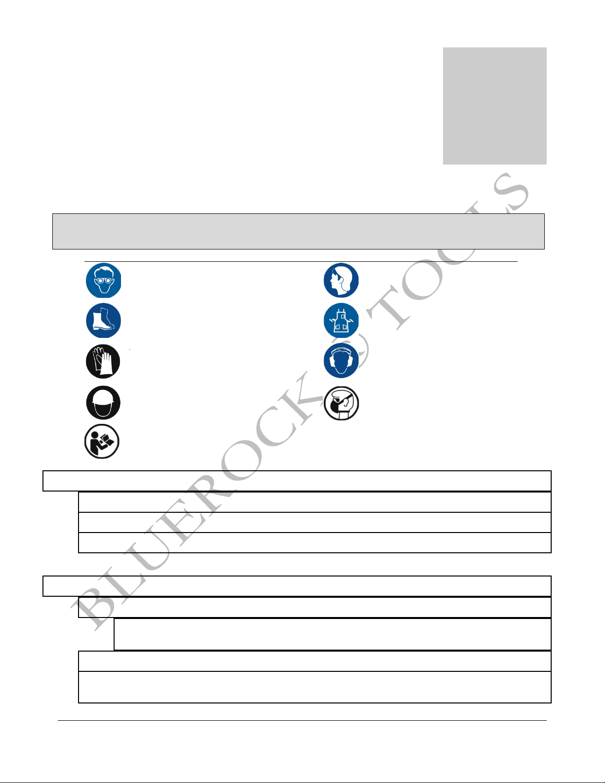
ØDO use a dust/fumes extraction system for cutting all materials. The operator should also
wear a protective respiratory device in accordance with welding safety standards.
ØDO NOT make adjustments to machine while the machine is running.
ØDO NOT remove or modify grounding plug. Only to be used on a properly grounded circuit.
ØDO NOT leave the flame running when not in use.
ØDO NOT hold the work piece by hand or using body. Always mechanically clamp or secure.
ØDO NOT allow flame too close to the machine body. This can cause machine components to
fail.
ØDO NOT allow flame to come in contact with power cords.
ØDO NOT operate machine outside of machine specifications.
ØDO NOT touch moving parts or cutting flame while the machine is running as death or
dismemberment could occur.
ØDO NOT stand under machine while running. The machine can fall and cause damage or
harm to the user.
ØDO NOT allow children or untrained personal to operate machine.
ØDO NOT use this machine in the rain or a wet environment. If using outdoors, make sure the
adhering surface is clean and dry.
ØDO NOT cut into steel that may contain a live electrical wire/circuit.

CG-211Y TORCH BURNER MACHINE
3
Specifications
MECHANICAL DATA
Forward or Reverse
Yes
Movement Type
Manual Hand Power
Wormwheel
Yes
Electricity Used
No
Cutting Tip Types
G02, G03 (similar to Airco Brand)
Minimum Pipe Cutting Diameter
4” (100mm) to 24” (600mm) with Chain Provided
With additional chain there is no maximum pipe size.
Cutting Depth
Up to 2” Thick (5mm min to 50mm max)
Cutting Speed
Manual – Depends on user
Cutting Movement Precision
0.039” per 40” (1mm/1000mm)
Bevel Angle
0-45 Degrees
Machine Main Structure Material
Alloy-aluminum (Zl101)
SHIPPING DATA
Shipping Weight
1) 32 lbs
Shipping Package Size
1) 13” x 13” x 17”
Included Accessories
DESCRIPTION
QTY
Instruction Manual
1
87” of Chain
1
Large Wheel (for smaller pipe)
2
Troch Bracket Assembly
1
G02 Oxy-Acetylene Cutting Tips
3
G03 Oxy-Propane Cutting Tips
3
Note
UPON RECEIPT, CHECK CAREFULLY TO ENSURE THAT THE MACHINE IS IN GOOD
CONDITION AND HAS ALL ACCESSORIES LISTED ABOVE.
Additional accessories for this machine can be found in BLUEROCK ® Tools online shop at
www.bluerocktools.com or from your local retailer.
Chapter
2

CG-211Y TORCH BURNER MACHINE
4
Cutting Tip Specifications
Type
Model
Cutting
Diameter
(mm)
Cutting
Thickness
(mm)
Cutting
Speed
(mm)
Oxygen
Pressure
(Mpa)
Acetylene
Pressure
(Mpa)
GO2Acetylene
Cutting tip
#00
0.8
5-10
600-450
0.2-0.3
>0.03
#0
1
10-20
480-380
0.2-0.3
0.03
#1
1.2
20-30
400-320
0.25-0.35
0.03
#2
1.4
30-50
350-280
0.25-0.35
0.03
#3
1.6
50-70
300-240
0.3-0.4
0.04
#4
1.8
70-90
260-200
0.3-0.4
0.04
#5
2
90-120
210-170
0.4-0.6
0.04
#6
2.4
120-160
180-140
0.5-0.8
0.05
#7
2.8
160-200
150-110
0.6-0.9
0.05
#8
3.2
200-280
90-60
0.6-1.0
0.05
#9
3.6
270-350
90-60
0.7-1.1
0.05
#10
4
350-400
70-50
0.7-1.2
0.06
G03Propane
Cutting tip
#0
0.7
5-10
800-450
0.2-0.3
>0.03
#1
0.9
10-20
480-300
0.2-0.3
0.03
#2
1.2
20-35
400-320
0.3-0.4
0.03
#3
1.5
35-60
350-280
0.3-0.4
0.03
#4
1.8
60-90
300-240
0.4-0.6
0.04
#5
2.1
90-130
260-200
0.4-0.6
0.04
#6
2.5
130-180
220-180
0.4-0.6
0.04
#7
2.7
180-250
200-160
0.5-0.7
0.05
#8
3.1
250-330
180-140
0.5-0.7
0.05
#9
3.5
330-380
130-90
0.6-0.8
0.05
#10
4
380-450
90-50
0.6-0.8
0.05

CG-211Y TORCH BURNER MACHINE
5
Operations
WARNING
DO NOT attempt to use this machine unless you are trained in its proper use as
well as trained in the proper use of gas cutting equipment. THOROUGHLY READ
THROUGH THE ENTIRE MANUAL BEFORE OPERATING THIS MACHINE!
PURPOSE
ØThe purpose of the CG-211Y is to cut steel pipe using oxy-acetylene or propane gas flame
cutting. The machine is designed to cut straight and bevel cuts. This machine is used for
seamless steel pipe cutting and beveling. It’s suitable for work in outside areas where there is
no electricity available.
OPERATIONAL PRINCIPLES
ØWhen placed on pipe, the main machine wheels rotate in a forward or reverse direction. When
engaged, the flame cuts into the steel. The machine speed can be increased or decreased using
human power. Using the adjusting knobs on the machine, the user can raise or lower the torch
holder.
oWARNING: Be careful not leave the machine cutting unattended as it may fall from the
end of the elevated work piece.
MACHINE COMPONENTS
ØThe main components of the CG-211Y are the clutch carriage, torch holder assembly, machine
body, wheels and chain
ØThis machine has two primary adjusting knobs to position the torch holder.
oThese knobs are both located on the torch bracket assembly and main spreader bar (see
figure below).
oThe spreader bar adjuster knob will adjust the torch holder left to right.
oThe side torch height knob will adjust the torch holder up or down.
Chapter
3

CG-211Y TORCH BURNER MACHINE
6
SETTING UP THE MACHINE
ØInstall the main spreader bar and the torch holder assembly.
oTighten the appropriate wing-nuts.
ØInstall the torch holder into the torch holder assembly.
oMake certain the inside if the torch holder is clean and does not have any burrs. Also
make certain any tips you use are free or burrs or defect. It is important the seats are
tight.
§See section below on “proper lighting of gas torch”
oFor straight cuts, ensure the torch holder is square (see figure below).

CG-211Y TORCH BURNER MACHINE
7
ØTighten the valve assembly side onto the top of the flat steel bar left of the main chain tightener
wing nut (see figure above). Ensure it is secured tightly.
ØInstall the large wheels if you are going to be cutting smaller pipe (see figure below).
oNote: You do not want the middle of the machine to high center on smaller pipe, hence
the need for the large wheels.
TRANSPORTING THE MACHINE
ØWhen transporting the machine, always carry under the machine wheels.
ØEnsure the torch tip is in a raised position so it will not get damaged when lifting up the machine
or putting down the machine on pipe.
ØIf transporting inside a vehicle, it is recommended to transport it on its side so as to avoid the
item falling over. It is also recommended to protect the wheels from damage by placing on non-
abrasive surface.
ØDO NOT carry the machine by the hoses.

CG-211Y TORCH BURNER MACHINE
8
RUNNING THE MACHINE
ØDo all pre-operational and operational safety checks from Chapter 1.
ØConsider your security and stability as well as the orientation of the machine in the work area.
oConsider the work surface material, condition, strength, density and rigidity. These
factors directly affect the tools use.
oWARNING: Ensure the piece being cut will be stable after the cut has been made.
ØEnsure the work surface and machine are free of debris, oil, etc.
oNOTE: The machine will deviate from the cut if the material is not clean (bare) and
seamless.
ØCarefully place machine at the start of the cut ensuring the wheels gently make contact with the
cutting surface. If cutting pipe, it is generally easiest to start at the top of the pipe.
ØAdjust the main chain tightening wing-nut so that the clutch carriage assembly is in a low
position.
ØLoop the chain through the top of the clutch sprocket and around the pipe.
ØInterlock the chain as in the illustration below.
oTake out the appropriate number of chain lengths so the chain is moderately tight.
oA quick way to figure out the specific number of chain lengths to use can be found using
the following equation:
§D=d+12
•D= The number of sections
•d= The diameter of pipe.

CG-211Y TORCH BURNER MACHINE
9
•12= Constant
•Example: d=299mm=29.9cm=30 sections of chain.
oD=30+12=42 Sections of Chain Total, So you would use 42
sections of chain for a pipe 299mm in diameter.
ØTighten up the main chain tightening wing-nut until the machine is adequately tight.
oDo not over-tighten wing-nut.
oEnsure the chain is at a straight 90 degree to the pipe.
ØEngage the clutch handle on the clutch carriage assembly. This should engage the worm-wheel
and allow for activated movement when the handle is turned.
oTurn the handle to ensure movement
ØSelect appropriate size torch tips for the application. Install tip.
ØSelect cutting angle.
ØConnect applicable gas lines.
oMake certain they are properly secured and there are no leaks. It is highly recommended
that leak testing be performed on the system prior to using the machine.
oEnsure the lines are long enough to complete the cut you are planning.
oALWAYS use gas tank cylinders with properly outfitted regulators/flowmeters.
ØEnsure the torch holder is not too close to the side of the machine body.
ØAdjust the side knobs to raise the torch tip to a suitable level for lighting.
ØLight the torch flame (see section below on proper lighting of torch flame).
ØAdjust the side knobs a suitable level for cutting though the material.
ØCut material by rotating the worm-wheel handle.
oCAUTION: Make certain the user is clear of the flame when manually rotating the handle.
ØWhen the cut is complete, stop the machine rotation.
ØShut off the torch flame.

CG-211Y TORCH BURNER MACHINE
10
PROPER LIGHTING OF GAS TORCH
ØBefore attempting to light the torch tip follow this check list:
oVerify the regulator pressure adjustment screws are backed out.
oVerify the torch valves are in the closed position.
oPosition yourself away from the front side of the regulator.
oSlowly open the oxygen valve and acetylene valve at the cylinder.
oAdjust regulator pressure adjustment screws to the tip pressure.
oOpen and close the torch valves at the machine separately and tune the regulator
pressure settings on the regulator.
ØLighting the torch:
oOpen gas valve ½turn.
oImmediately ignite flame with striker.
§CAUTION: Light flame immediately so gas does not enter machine body or
general atmosphere around the machine.
§Ensure proper ventilation around the work area.
oIncrease gas flow until flame leaves end of tip and smoke is not present.
oDecrease until flame goes back to tip.
oOpen pre-heating oxygen valve and adjust until neutral flame is achieved.
oWhen the temperature of the steel is suitable temperature for the steel plate, open the
cutting oxygen valve.
oAfter adjustment of the flames efficiency, turn on the machine rotation.
ØAfter cutting is complete, close oxygen cutting valve.
ØNext close pre-heating oxygen valve.
ØLastly, close the gas-cutting valve.

CG-211Y TORCH BURNER MACHINE
11
ØIf done using the machine, close oxygen and gas valves on the main cylinder regulators.
oPurge oxygen and gas lines.

CG-211Y TORCH BURNER MACHINE
12
Troubleshooting
Note
SERVICING SHOULD ONLY BE DONE BY A QUALIFIED TECHNICIAN.
No
Problem
Cause
Solution
1
Leak gas
and/or flame in
the joint of
torch and
torch cutting
tip.
1. The torch holder inlet is damaged.
2. There is copper burr or materials on the
surface of the torch tip.
1. Softly grind the torch cone with small sand paper to clean
out the burr.
2. Clean the material on the cutting tip. Softly grind the
surface with small sand paper. Change the cutting tip if it is
badly damaged.
2
The flame
goes out as
soon as the
oxygen valve
is opened
The cutting oxygen leaked into the preheating
oxygen area.
1. Copper stain or useless materials on the inner
part of torch
2. The smaller cone of torch cutting mouth was
stuck with some with material or was damaged.
1. Softly grind the most inner part of torch holder with sand
paper to clean out the debris or damage.
2. Softly grind the smaller surface of the cutting mouth.
Change the cutting mouth if it is serious damaged.
3
The steel can’t
be cut through
1. The torch cutting-tip is too small.
2. The flame frequency is not strong enough
3. Low pressure for cutting oxygen
4. The hole channel of cutting mouth may be
jammed
5. The cutting oxygen is not pure.
6. The cutting oxygen was leaked into the
preheating oxygen hole channel.
1. Choose the cutting tip spec according to the cutting
thickness.
2. Increase flame frequency properly.
3. Properly increase the cutting oxygen to ensure the enough
flow speed of cutting oxygen.
4. Clean the useless materials in the torch cutting mouth with
cutting pin.
5. Use oxygen with more than 95% purity.
6. Clean the useless materials on the cutting mouth and
torch, repair the damaged surface and change cutting mouth
if needed.
4
The cutting is
not straight
enough.
1. The steel pipe was deformed.
2. The flame line was not straight.
3. Uneven pipe surface
4. The torch was poorly fixed and can be moved.
5. The chain is not straight
1. Use round steel and calibrate it before cutting.
2. The torch should have a 90o angle with the steel and tightly
fixed. Clean the useless materials in the torch cutting mouth
with cutting pin.
3. Fix surface irregularities.
4. Tighten all connections.
5. Straighten the chain.
5
The clutch will
not engage.
1. The clutch carriage is damaged
2. The clutch is dirty
1. Repair or replace the carriage
2. Lubricate the clutch and ensure it moves freely
Chapter
4

CG-211Y TORCH BURNER MACHINE
13
General Maintenance
ØInspect valve assembly connections.
ØLubricate all moving parts in the clutch assembly.
ØKeep machine clean and free of debris.
oMake sure to frequently clean metal scraps from the roll wheels.
ØCheck for misalignment, binding and breakage of all moving parts. If damaged, repair tool before use.
ØCheck to ensure the torch holder is clean and free of debris.
oInspect the inside of the holder as well.
ØInspect all torch tips and ensure they are not damaged and the small cutting holes are clean.
ØInspect cutting hoses to ensure they are not damaged.
ØDO NOT oil and connection points used in the gas/oxy system!
Chapter
5
Table of contents
Popular Welding System manuals by other brands

Lincoln Electric
Lincoln Electric POWER MIG IM736-D Operator's manual

WIELANDER+SCHILL
WIELANDER+SCHILL Inverta Puls IP6-2 ACT Operation manual

Cebora
Cebora SYNSTAR 330 TS instruction manual

Hobart
Hobart DP-3035 Specification sheet

Lincoln Electric
Lincoln Electric IDEALARC CV 505 Operator's manual

Master
Master PROHEAT PH-1200A instruction manual

Purelogic
Purelogic MetalCut 100 Operator's manual

EWM
EWM Drive XQ AC operating instructions

Thermal Dynamics
Thermal Dynamics Ultra-Cut 400 Operation manual

Lincoln Electric
Lincoln Electric FlexCut 80 CCC Operator's manual

CIGWELD
CIGWELD W4016300 instruction manual

Advance Welding
Advance Welding ACT 80V operating manual