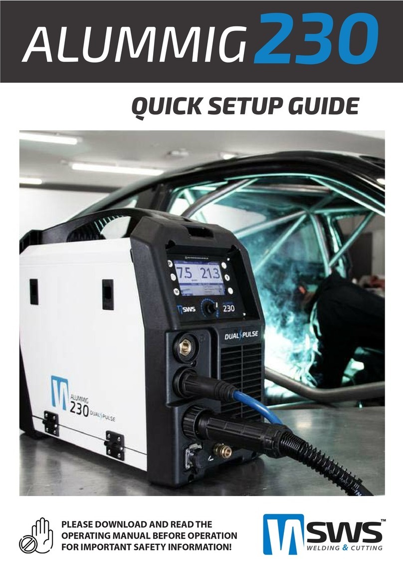
SWS ALUMMIG 230 User manual

ALUMMIG™ Dual Pulse MIG Welder
Operating Manual
www.swswelding.com.au

THANK YOU FOR YOUR PURCHASE OF THE ALUMMIG™ 230 Digital TIG/MMA
WELDING SYSTEM.
At SWS, we take pride in the professional quality, innovation, and support we deliver to our customers and
the welding industry as a whole. The ALUMMIG™ 230 is the next step in our progression as the new standard
in welding and cutting products delivered fast marking the continuing evolution of SWS. This welding
machine is the latest development in inverter technology. It has been tested and approved by production
welders and the best fabricating professionals in the industry.
Providing better outcomes through innovation and new product creation have been staples of SWS since
its inception. It is the very principle by which we do business. Our goal has always been to provide an
outstanding product that not only stands out from the competition but also reflects the quality we strive
for in every aspect of our business philosophy. From our second to none customer service excellence to
technical support, we work hard at what we do so that you can too.
We know you will enjoy using this machine!
The ALUMMIG™ 230 is manufactured and compliant with AS60974.1:2006, IEC60974.10, CE
Guaranteeing you electrical safety and performance.
CAUTION!: The ALUMMIG™230 Operating Manual has been designed to instruct you on the proper use
and operation of your SWS product. Your satisfaction with this system and its safe operation is our primary
concern. It is important to take the time to read the entire manual, especially the safety sections. They will
help you to avoid potential hazards that may exist when working with this product.

This warranty covers
1. The Product only described against labour and faulty materials.
2. The replacement of parts and the repair labour used, for the remainder of the warranty period.
This warranty does not cover
1. If repairs are made or attempted by someone other than SWS Australia.
2. Normal wear and tear. Parts such as control boards main PCB boards etc. must be regularly inspected and kept as
dust-free as possible.
3. Abuse, misuse, the subject of an accident, being dropped, crushed, impacted with any hard surface, exposed to
extreme heat (including fire) or cold, improper maintenance, continued use aer partial fail.
4. Acts of God, vermin or foreign matter entering, e.g. dirt and moisture. The tool should be regularly blown out with low-
pressure air if the equipment is used near metal shavings.
5. If the Product has been modified, incorrectly adjusted or operated, the subject of incorrect electrical supply or
inconsistent supply, or used with inappropriate accessories.
6. If the Product is tampered with or if any event of force has caused the damage.
7. If the Product has not been used or maintained in accordance with the manufacturer’s instructions as provided with
the product.
8. If the Product’s serial number, as applied by the manufacturer, has been altered or removed from the product.
Liability
To the extent permitted by law (including the Competition and Consumer Act 2010( Cth) or New Zealand Consumer
Guarantee Act 1993), in no event shall SWS, be liable for consequential, incidental or indirect damages or other losses or
expenses incurred because of use or sale of the product.
How do you make a claim under warranty?
If your product may be faulty, please contact SWS so a qualified technician can diagnose any issues and the equipment
can be returned to make warranty repairs, if necessary.
Australia/New Zealand
For service in Australia and New Zealand, the customer should contact the Australian Customer Service line on (03) 5766
2331
Return to SWS
If you qualify for a warranty claim, you will not be liable for any postage costs along with parts and labour. If you do not
qualify for a claim, you will incur all expenses including postage cost and parts and labour for the repairs. All warranty
claims and non-claimable maintenance will be done within one business day to ensure minimum downtime.
Important information
This warranty is in addition to all other rights and remedies you have under the Competition and Consumer Act 2010
(Cth) and the New Zealand Consumer Guarantee Act 1993 and any other laws in relation to the Products. Our goods
come with guarantees that cannot be excluded under the Australian Consumer Law. You are entitled to a replacement or
refund for a major failure and compensation for any other reasonably foreseeable loss or damage. You are also allowed
to have the goods repaired or replaced if the products fail to be of acceptable quality, and the failure does not amount to
a significant failure. Goods presented for repair may be replaced by refurbished goods of the same type rather than being
repaired. Refurbished parts may be used to repair the products.
WARRANTY INFORMATION
This product comes with a 3 year warranty, for an extra 2 years extension
please go to our website create a MY SWS ACCOUNT and register the
equipment. This also helps us to assist you quickly in the event of a claim
and gives you access to the MY SWS support portal.
SPECIALISED WELDING SYSTEMS
WEBSITE: WWW.SWSWELDING.COM.AU
EMAIL: [email protected]OM.AU
TELEPHONE: (03) 5766 2331
Manual Version 1.0
1
INTRODUCTION
1.0 Welcome
The SWS ALUMMIG™ 230 is one of the most advanced, feature-packed and aordable digital MIG welding
systems on the Australian market for welding of ferrous and non-ferrous metals. Featuring smart
programming makes setting up easy for the beginner and versatile for the pro. You can depend on the
ALUMMIG™ 230 to weld all day at its rated capacity and to pack more punch when you need it most.
Latest Inverter Technology
Embedded microprocessor with Infineon
components delivers ultimate durability and perfect
welding characteristics.
Revolutionary Digital Display
Large high visibility durable display allows easy
viewing from a distance and continually provides
you with necessary feedback for optimum welds.
Dual Pulse
When welding thin gauge materials and joints like
thin sheet metal and outside corners pulse allows
you to focus the arc increase travel speed and
minimise warpage.
Superior Duty Cycle
Make bigger longer welds with ease. The duty cycle
of 40% at 230 Amps and 100% at 140 Amps (40°C)
gets most if not all jobs done.
Highly Portable
Dependable IGBT inverter technology ensures a
highly portable and lightweight unit weighing only
15kg.
Meets the Highest Standards
Meets and exceeds the latest Australian, NZ and
International electrical and electromagnetic
compatibility standards. AS60974.1:2006,
IEC60974.10, CE

Manual Version 1.0
2
SPECIFICATIONS
1.1 Specications
Processes Manual MIG, Single Pulse MIG, Dual Pulse MIG, Synergic MIG, TIG, Pulse
TIG, MMA
Current Type DC
Weldable Metals Aluminium, Mild Steel, Stainless Steel, Specialty Metals
General Aluminium, Steel and Stainless Steel Fabrication, Stainless Steel
Tank and Pipe Fabrication, Boat Building / Shipyards, Motorcycle custom
Industries shops, Automotive customs shops, Automotive Components and Repairs,
Motorcycle Components and Repairs, Technical Schools, Aerospace,
Agriculture, Farming, Building and Construction, Home Repair
Workshops.
Input Voltage/Hz 1 Phase 230V +/- 15% (15 Amp Plug) 50/60 Hz
Minimum Generator 6.6kW (8.5kVA at 0.8 PF)
Duty Cycle 40°C AMB (TIG/MMA) 40% @ 230A, 100% @ 140A
Welding Current Range (TIG/MMA) 10-230 Amps
Dimensions L 435mm H 360mm W 220mm
Weight 15Kg
Warranty 5 Years registered (3 Years standard)
Manufactured to Standards AS60974.1:2006, IEC60974.10, CE

Manual Version 1.0
3
WARNING
Arc welding and plasma cutting can be dangerous to yourself and others. Take special care when
welding and cutting. Note your employer’s safety practices which should be based on manufacturers’
hazard data documents.
ELECTRIC SHOCK - Can kill
- Connect and earth (ground) the welding or plasma cutting unit adhering to applicable standards.
- Do not touch live electrical parts or electrodes with bare skin, wet gloves or wet clothing.
- Insulate yourself from the natural ground and the workpiece.
- Ensure your working stance is safe.
FUMES AND GASES - Can be dangerous to health.
- Keep your head out of the fumes.
- Use ventilation, extraction at the welding or cutting arc, or both, to take fumes and gases away
from your breathing zone and the surrounding area.
ARC RAYS - Can injure eyes and burn skin.
- Protect your eyes and body. Use an approved welding/plasma cutting helmet and filter lens and
wear protective clothing.
- Protect bystanders with suitable screens or curtains.
FIRE HAZARD
- Sparks (spatter) can cause fires. Make sure therefore that there are no flammable materials
nearby.
NOISE - Excessive noise can damage hearing.
- Protect your ears. Use ear mus or other suitable hearing protection.
- Warn all bystanders of the risk.
MALFUNCTION - Call an for expert assistance in the event of a malfunction.
CAUTION
This product is only intended welding. Any other use may result in personal injury and
equipment damage.
CAUTION
Read and understand the instruction manual before installing or operating.
SAFETY
2.0 Hazards

Manual Version 1.0
4
SAFETY
2.1 Precautions
Users of SWS welding and plasma cutting products have the primary responsibility for ensuring that anyone
who works on or near this equipment adheres to all the relevant safety precautions. The following listed
recommendations must be observed along with the standard regulations that apply to the workplace.
All use must be carried out by trained personnel well versed with the safe operation of the equipment.
Incorrect operation of plasma cutting or welding equipment may lead to hazardous events which can result
in serious injury to the user and damage to the equipment. Safety precautions must meet the requirements
that apply to this type of welding or plasma cutting equipment.
1. Persons who use welding or plasma cutting equipment must be familiar with the following:
- Welding and plasma cutting machine operation
- Location of emergency stops
- The machines purpose
- Relevant safety precautions
- Arc welding and / or hand held plasma cutting
2. The user must make sure that:
- No unauthorized person in the vicinity of the working area of the equipment when it is used.
- No person is unprotected when the arc is started.
3. The workplace must:
- Be suitable for the purpose
- Be free from weather
4. Personal safety equipment:
- Always wear approved personal safety equipment, such as welding helmets, safety glasses, flame proof
clothing and safety gloves.
- Never wear loose fitting items, such as hooded jumpers, bracelets, rings, etc., which can become trapped
or cause serious injury burns.
5. General safety precautions:
- Ensure the return cable is connected securely.
- Work on high voltage equipment must only be carried out by a qualified electrician or electrical
technician.
- Approved fire extinguishing equipment must be clearly marked and in the vicinity.
- Lubrication and maintenance must not be carried out on the equipment during operation.
READ AND UNDERSTAND THE OPERATING MANUAL BEFORE
INSTALLING OR USING THIS EQUIPMENT - ALWAYS PROTECT
YOURSELF AND OTHERS!

Manual Version 1.0
5
SERVICE
7.0 General Maintenance
3 Months
6 Months
Carefully clean exterior of power source with a dry brush.
Unplug the power source remove cover and visually check and carefully clean the interior without touching
any internal electrical components, wires or PCB boards and by taking special care not to damage any
components. Use compressed air set at no more than 70 Psi to carefully blow out all dust and debris.
Warning!
There is extremely dangerous voltage, and power levels present inside this
product. Do not attempt to open or repair unless you are a qualified electrical
tradespersons and you are qualified in training in power measurements and
troubleshooting techniques. If major complex sub-assemblies are faulty, then the
Power Source must be returned to an accredited service provider.

Manual Version 1.0
6
1
2
3
4
5
6
7
8
9
10
11
12
FRONT PANEL
1. Program - Select torch trigger mode and welding programs
2. Settings - Go to the settings menu
3. Memory - Save, Load or delete a program
4. Back - Go back to previous screen
5. Wire Feed - Fast feed use when installing new wire rolls
6. Gas Check - Check gas ow and or use as purge function
7. Rotary Encoder - Select and change functions
8. DCEP Port - Direct current electrode positive port
9. DCEN Port - Direct current electrode negative port
10. MIG EURO Port - MIG Torch port
11. Switch Port - Connect the TIG torch, Spool gun or Push Pull gun
12. Gas Outlet - Connect the TIG torch gas line

Manual Version 1.0
7
SIDE DOOR
1
2
3
5
4
1. MIG Torch EP Terminal - Electrode positive terminal with this connected the MIG torch
is positive (EP) the ground lead goes to (-) port
2. MIG Torch EN Terminal - Electrode negative terminal with this connected the MIG
torch is negative (EN) the ground lead goes to (+) port
3. Wire feeding unit
4. MIG wire spool carrier 200mm Diameter rolls only
5. Select spool gun or MIG torch and push pull torch operation

Manual Version 1.0
8
GMAW SETUP
1
2
3
4
5
1. For EN (Electrode Negative) MIG welding connect the ground cable
2. For EP (Electrode Positve) MIG welding connect the ground cable
3. Connect the MIG torch and use retaining nut to secure
4. If using a spool gun or push pull gun connect into socket
5. If using GAS connect the Gas line here to regulator
6. Select the chosen MIG welding mode

Manual Version 1.0
9
MMA SETUP
1
2
1. Connect the MMA Torch
2. Connect the Ground cable
3. Select MMA welding mode

Manual Version 1.0
10
GTAW SETUP
1
2
3
4
1. Connect the ground cable
2. Connect the TIG torch cable
3. Connect the TIG torch switch wire
4. Connect the TIG torch gas line
5. Connect the GAS line from regulator
5

Manual Version 1.0
11
MAIN MENU
MMA - Stick welding mode and is used for the MMA arc welding process.
LIFT TIG - LIFT ARC TIG mode and includes pulse.
Manual MIG - Normal MIG welding mode so the wire speed and volts is set by the user.
Synergic MIG - The user can select the program then the machine adjust parameters
accordingly for best results.
Single Pulse - The Pulse is set synergically and you can choose from a variety of preset
programs.
Dual Pulse - Pulse Frequency and ratio can be set to further ne tune the welding
characteristics. You can choose from all common welding consumables.
From the main menu you can choose from GMAW, GTAW, or MMA welding modes. The
screen will also display the current user and date in the top bar.

Manual Version 1.0
12
GMAW FUNCTIONS
1. Program selection display - The top bar displays the welding modes selected.
2. Wire Speed - This adjusts the wire speed and corresponding amperage and will be a
dierent ratio depending on the welding program selected.
3. Voltage and Arc Length - This adjusts the voltage which is relevant to the arc length
and heat input. - 10 is a longer arc length with less heat and 10 is a short arc length with
more heat.
4. Material Size - This gives an approximate size of the material being welded. It is only
used as a starting point always a good idea to setup the machine on some scrap materi-
al rst to prevent a poor weld.
5. 4T and 4T S Values - Adjust the amps / volts used for the torch trigger
6. Welding Parameters
Dual Dynamic - Percentage of dual pulse peak and base current utilised (- 10 to 10)
Dual Frequency - Sets the pulse frequency from (0.0 - 5.0 Hz) 1 Hz is 1 pulse per
second.
Inductance - Adjust the rate of current rise following the short-circuit state thicker
metals generally use higher inductance settings.
Run In Speed - This slows down the speed in which the wire is fed into the work piece.
If wire stubbing or poor Arc starts are occurring use a low value setting of 0 the
maximum setting is the full run in speed.
Hot Start - Increases the initial welding amperage (0 - 10) higher settings can help with
arc starts.
Burn Back - Adjusts the amount of wire sickout after welding has stopped (0 -10) a
higher number will produce a longer wire length.
Gas Preow - Adjusts the amount of time the gas ows for before the arc starts (0 - 3.0)
Gas Postow - Adjusts the amount of time the gas ows for after the arc stops (0 - 6.0)
1
23
456

Manual Version 1.0
13
TORCH TRIGGER MODES
2 Step - Pull and hold the trigger to weld release to stop welding.
4 Step - Pull trigger for 1 second then release the to start welding pull trigger to activate
last value welding parameters. Release to stop welding.
4 Step Special - Pull and hold trigger for rst welding parameters, release for main
welding parameters, pull and hold for last welding parameters.
Tack - Set the welding on time in seconds for consistent tack welds. (This parameter can
be found in the MIG welding mode screens parameter box once selected)
The torch trigger modes can be used to change the welding amperage and voltage
while welding. This can be useful for when welding aluminum to use higher values
at the start of the weld and lower at the end as the metal heats up preventing burn
through and as a crater current.

Manual Version 1.0
14
GMAW PROGRAMS (DUAL PULSE)
NOTE: There is dierent programs available for the Synergic, Single and dual pulse
program modes. When in manual mode the machine works as a regular MIG with the
wire feed speed to amperage ratio set at factory specications.
From the programs menu you can select all common welding wires and the machine
will calculate the correct wire speed to amperage ratio along with voltage inputs.

Manual Version 1.0
15
GMAW PROGRAMS (SINGLE PULSE)

Manual Version 1.0
16
GMAW PROGRAMS (SYNERGIC)

Manual Version 1.0
17
GTAW FUNCTIONS
Start Amps - Initial welding maps
Upslope - Time to the main welding amps
Down Slope - Time to the last welding amps
End Amps - Last welding amps
Gas Preow - First gas before welding starts
Gas Post Flow - Time of gas ow after the welding stops
Pulse Frequency - Pulses Per Second at the peak amps
Pulse Peak Time - Time spent at the peak amps setting
Pulse Peak Current - Pulse peak current
The GTAW welding mode uses lift arc to establish the arc. This is done by pressing the
trigger switch then lifting the tungsten o the work piece with the torch the arc will then
start.
Other manuals for ALUMMIG 230
1
Table of contents
Other SWS Welding System manuals