BLUEROCK BRM-35A Quick start guide

OPERATIONAL MANUAL
MODEL: BRM-35A / BRM-35A_BMAGNETIC DRILLING
MACHINE
by BLUEROCK ® Tools
Volume
1.1

MWS-BRM-35A/B MAG DRILL
UNPACKING THE ITEM
Caution: This machine is packed together with items that may be sharp, oily and overly heavy objects.
Remove the machine from the packaging in a safe manner. Check to ensure all accessories are included with
the item while unpacking. If any parts are found to be missing, contact the retailer as soon as possible. Do
not throw away the packaging until the item is out of the guarantee period. Dispose of the packaging in an
environmentally responsible manner. Recycle if possible. Keep all plastic bags away from children due to
risk of suffocation.
WEEE - Waste Electrical & Electronic Equipment. Note this machine should be disposed of as electrical & electronic waste.
©THE NEWMAN TRADING COMPANY LLC DBA BLUEROCK® TOOLS 2016
1100 SW 16th St • Suite D
Renton, WA 98057
Phone 206.604.8363 • Fax 425.572.5167
www.bluerocktools.com

BRM-35A/B MAG DRILL
Table&of&Contents&
SAFETY' 1!
PRE-OPERATIONAL SAFETY CHECKS! 1!
OPERATIONAL SAFETY CHECKS! 1!
SPECIFICATIONS' 4!
INCLUDED'ACCESSORIES' 4!
ADDITIONAL'AVAILABLE'ACCESSORIES' 5!
ADDITIONAL ACCESSORIES FOR THIS MACHINE CAN BE FOUND IN BLUEROCK ®TOOLS ONLINE SHOP AT
WWW.BLUEROCKTOOLS.COM OR FROM YOUR LOCAL RETAILER.! 5!
OPERATIONS' 6!
PURPOSE! 6!
OPERATIONAL PRINCIPLES! 6!
MACHINE COMPONENTS! 6!
TRANSPORTING THE MACHINE! 7!
RUNNING THE MACHINE! 8!
INSTALLING ANNULAR CUTTERS!10!
TROUBLESHOOTING'11!
GENERAL'MAINTENANCE'12!
OCCASIONAL'MAINTENANCE'12!
PARTS'LIST'13!
BREAKDOWN'VIEW'14!

BRM-35A/B MAG DRILL
1
Safety
DO NOT USE THIS MACHINE UNLESS YOU HAVE READ THE
OPERATING INSTRUCTIONS!
Safety glasses must be worn at all
times in work areas.
Long and loose hair must be
contained.
Appropriate footwear must be worn.
Close fitting/protective clothing
must be worn.
Safety gloves should be worn at all
times and jewelry must not be worn.
Hearing protection should be
worn when using this machine.
Hard-hat must be worn while using
machine.
Dust mask must be worn while
using this machine.
Read operational manual prior to use.
PRE-OPERATIONAL SAFETY CHECKS
ØExamine the power cord and plug for damage. This tool is supplied with a ground plug and
must always be used with the proper grounded circuit.
ØExamine the body of the machine and inspect for damage or defects.
OPERATIONAL SAFETY CHECKS
ØONLY to be operated by qualified personal who have read instructions.
oNOTE: Failure to read and follow instructions could result in electrical shock, fire,
property damage and/or serious injury!
ØDO ensure all non-essential people are clear of the immediate work area.
ØDO keep body parts, clothing & power cords clear of turning/cutting pieces.Stay alert and
use common since when using this tool.
Chapter
1

BRM-35A/B MAG DRILL
2
ØDO allow machine to reach operating speed before starting a hole.
ØDO unplug machine while changing or adjusting cutting bits so as not to accidentally turn
machine on.
ØDO remove adjusting keys or hex wrenches prior to turning the machine on.
ØDO use cutting paste (instead of cutting oil) when using this drill in an inverted position to
prevent oils from entering the electrical system and for ease of cutting.
ØDO tie a loop in any extension cord connections to prevent cords coming apart and a loss of
power.
ØDO guard against electric shock by preventing body contact with grounded surfaces such as
pipes, radiators, ranges, refrigerators, etc.
ØDO be mindful that power tools can expose an operator to vibrations transmitted trough
contact with the machine. Prolonged exposure can lead to medical issues which should be
discussed with a medical professional.
ØDO tie in a drip loop in the power cord to prevent cutting fluid from running into the power
receptacle.
ØDO use a dust extraction system for cutting materials that create dust such as cast iron. The
operator should also wear a protective respiratory device.
ØDO NOT make adjustments to machine while the machine is running.
ØDO NOT switch off the machine when it is under load, except in an emergency.
ØDO NOT remove or modify grounding plug. Only to be used on a properly grounded circuit.
ØDO NOT leave the machine running when not in use.
ØDO NOT hold the work piece by hand or using body. Always mechanically clamp or secure
work piece.
ØDO NOT allow coolant oil to enter the machine’s ventilation system.
ØDO NOT operate machine outside of machine specifications.
ØDO NOT touch moving parts while the machine is running as death or dismemberment could
occur.
ØDO NOT remove machine metals panels while machine is connected to a power source. Only
to be removed for service by qualified personal and put back on the machine after service is
complete.
ØDO NOT allow children or untrained personal to operate machine.
ØDO NOT use this machine in the rain or a wet environment. If using outdoors, make sure the
adhering surface is clean and dry.
ØDO NOT operate in the presence of explosive materials as power tools create sparks which
may ignite dust or fumes.
ØDO NOT drill into an area that may contain a live electrical wire/circuit.

BRM-35A/B MAG DRILL
3
ØDO NOT operate this machine on the same work surface where welding is being performed.
This could result in severe damage to the machine or personal injury to the user.
ØDO NOT use this machine without the safety chain or safety strap.
ØDO NOT operate this machine on a lower voltage as it may result in the electromagnet being
at a reduced power level and the machine could become unstable while cutting. This could
also limit the motor life.
oNOTE: Use of long small gauge power extension cords can result in decreased
voltage. As local voltages can vary, it may be a good idea to test the voltage at the
end of the extension cord to ensure proper voltage requirements are met. You might
also consult an electrician to make sure the length of cord matches up with the proper
wire gauge for this size motor. Make sure to use outdoor cords when operating
outdoors.
BRM-35A/B MAG DRILL
4
Specifications
ELECTRICAL DATA
Voltage
120V, 50-60Hz
Current
10 Amps
Motor Size
1200W
Power Connection
US Standard 3 Prong Type B Plug
MECHANICAL DATA
Cutter Range
Annular Cutter: 7/16” Min to 1.5” Max (12mm - 35mm)
Twist Drill Bit: 1” Max
Cutting Depth
2” Max Depth
Cutting Speed
595 RPM One Speed Gearbox
Tool Holder
Direct Arbor with ¾” Weldon Shank
Magnetic Adhesion
2600 Lbs (13000N)
Stroke
6.5” - Only short twist drill bits can be used with this drill.
SHIPPING DATA
Shipping Weight
40 Lbs
Shipping Carton
19” x 8” x 15”
Included Accessories
DESCRIPTION
QTY
Instruction Manual
1
Coolant/Oil Bottle
1
Feed Handles
3
Chuck, Adapter and Key
1 ea
Safety Chain
1
Plastic Case (for protection during shipping)
1
Hex Wrench
2
Chapter
2

BRM-35A/B MAG DRILL
5
Note
UPON RECEIPT, CHECK CAREFULLY TO ENSURE THAT THE
MACHINE IS IN GOOD CONDITION AND HAS ALL
ACCESSORIES LISTED ABOVE.
Additional Available Accessories
Additional accessories for this machine can be found in BLUEROCK ® Tools
online shop at www.bluerocktools.com or from your local retailer.
DESCRIPTION
13 Pc 2” Depth HSS Annular Cutter Set with Centering Pin
6 Pc 2” Depth HSS Annular Cutter Set with Centering Pin
6 Pc 1” Depth HSS Annular Cutter Set with Centering Pin
5/8” Screw In Chuck HD Heavy Duty and Key
5/8” Taper Chuck HD Heavy Duty and Key
5/8” Taper Chuck Black Medium Duty and Key

BRM-35A/B MAG DRILL
6
Operations
Note
THOROUGHLY READ THROUGH THE ENTIRE MANUAL BEFORE
OPERATING THIS MACHINE!
PURPOSE
ØThe purpose of the BRM-35A is to drill through steel using annular cutters or
standard twist drill bits (when using the optional drill chuck).
ØThese drills are designed to magnetically adhere to a ferrous surface using their
electromagnetic base. Generally these drills are designed and used to drill through
mild steel. This magnetic base will not work without a power connection.
oNOTE: The entire magnetic base must cover the work area to have full
magnetic adhesion. Using only a portion of the magnet is dangerous! Make
sure the base fits completely on the surface.
ØThese machines can be used vertically, horizontally or overhead (inverted) provided
strong enough magnetic adhesion and an acceptable work environment. NOTE: For
safety, the safety chain should always be used incase of an accidental power failure
or other loss of magnetic adhesion.
OPERATIONAL PRINCIPLES
ØThe main drilling shaft rotates in the forward direction. The main drilling motor
connects to the tool holder to make contact with a surface and slowly bore a hole.
Using the feed handles on the side of the drill, the user can raise or lower the drilling
motor.
MACHINE COMPONENTS
ØThe main components of the BRM-35A are the tool holder, gearbox, motor, frame and
magnetic base. The tool holder is driven by the transfer case and the motor.
oThese components must be not be removed except by a qualified technician.
Power must be disconnected prior to any service.
Chapter
3

BRM-35A/B MAG DRILL
7
ØThis machine has one primary adjusting point for the travel between the magnetic
base frame and the drill frame slide. The main way to increase or decrease the users
ability to move the drill by hand is with this system. These are the black hex bolts on
the side of the machine that have a locking nut around them. These are generally
used to tighten up the travel as the brass slides wear over time. Be mindful to evenly
adjust these so that the travel is even and smooth. The ideal travel generally keeps
the drill in place when the user is not using the drill (this is usually on the tighter
side) although individual users needs may vary.
TRANSPORTING THE MACHINE
ØWhen transporting the machine, always use the carrying handle.
ØEnsure the drilling head is at the lowest position.
ØDO NOT transport the machine with cutters or bits in the tool holder.
ØIf the coolant bottle is connected, ensure the valve is in the “off” position or the
coolant has been drained.
ØIf transporting inside a vehicle, it is recommended to transport it on its side so as to
avoid the item falling over.
ØIf possible, transport in a case.
ØDO NOT carry the machine by the cord.
ØDO NOT allow the cord or plug to drag along the floor when transporting.
1) Carbon Brush Holder
2) Drill Motor
3) Gearbox
4) ¾” Weldon Shank Tool Holder
5) Optional Annular Cutter (not
included)
6) Drill Frame Slide
7) Magnetic Base
8) Feed Handle
9) Motor On Switch
10) Motor Off Switch
11) Magnet On/Off Switch

BRM-35A/B MAG DRILL
8
RUNNING THE MACHINE
ØDo all pre-operational and operational safety checks from Chapter 1.
ØConsider your security and stability as well as the orientation of the machine in the
work area.
oConsider the work surface material, condition, strength, density and rigidity.
These factors directly affect the tools magnetic adhesion. Magnetic adhesion
diminishes with thinner material and rough surface. Full magnetic spec’d
adhesion is considered on 1” material. When using on material 3/8” or less,
the drill should be mechanically clamped to the work-piece.
ØAfter placing the machine in work area, connect the safety chain.
oThe safety chain should attach to the machine (preferably through the
carrying handle) as well as attached to the work area in such a manner that
prevents the machine from detaching or falling from the work area in the
event of magnetic deactivation or lost adhesion.
ØEnsure the feed handles are securely attached to the feed spindle.
ØEnsure the work surface and bottom of magnet are free of debris, oil, etc.
ØSelect appropriate size tool holder, chuck or adapters.
ØSelect and set up oiling method or cutting pastes.
oIf drilling overhead or horizontal use cutting paste liberally applied to the
cutting bit.
ØIf using the machine horizontally with the oil bottle, connect bottle to the side of the
machine using the two set screws located on the drill frame.
oConnect the oil bottle tube into the side of the tool holder by firmly pressing
in the hose.
§To remove the hose later, press in the plastic piece around the hose
towards the tool holder while simultaneously pulling the plastic hose
away from the tool holder.
oMake sure the oil bottle valve is in the off position.
§This is generally at a 90 degree angle from the valve hose.
oFill the oil bottle with cutting fluid.
ØSelect appropriate size annular cutter or standard twist drill bit.
oThe ¾” Weldon shank uses two Allen head bolts. The annular cutters will go
in the shank and be secured on the two flat sides by the two Allen head
screws. See next section below for more specifics on using annular cutters.
oIf using a standard twist drill bit you will can use the drill chuck with a ¾”
Weldon shank adapter. Secure the chuck into the Weldon shank using the
same method as standard annular cutters. Tighten the bit into the chuck.

BRM-35A/B MAG DRILL
9
ØPlug the machine into power source.
oForm a loose knot in the power cord close to the plug connection to prevent
cutting fluid from running down the cord and into the power receptacle.
ØEngage the magnet by pressing the magnet button on the control panel.
oCheck that the machine is firmly attached to the work area.
oNOTE: The motor will not start unless magnet is on.
ØTurn feed handle raising the cutter until the bit is above the work surface.
ØOpen the oil bottle valve to allow oil to come out to the work surface.
oYou may have to gently squeeze or shake the bottle to get the oil to start
flowing.
ØTurn the machine on.
oStart the machine by pressing the green “on” switch. Stop the machine by
pressing the red “off” switch.
ØVery slowly engage the cutting bit with the material surface by lightly engaging the
hand crank down towards the material.
ØAfter about 1/16” of cutting has been achieved in the work surface, slightly more
force can be applied. This will be the normal amount of force the rest of the hole.
oNOTE: Do not force the hole. Let the machine do most of the work.
Excessive physical effort should be avoided as it can cause damage to the
machine or the user.
oIf the unit jams in a hole, stop the drill immediately to prevent injury.
Disconnect the drill from the power supply and loosen the cutter by turning
drill spindle counterclockwise. Never attempt to free cutter by starting motor!
ØMake sure to keep the cutting material adequately lubricated.
ØEase up on feed pressure as the cutter starts breaking through the backside of the
material.
oIf using annular cutters with a centering pin, the slug should eject using the
spring-loaded mechanism in the drill shank. Be mindful that this slug can
eject at a rapid rate, so be sure all is clear on the output side of this slug to
prevent injury to persons or property.
ØFinish drilling the hole.
ØTurn the motor off and disconnect power once the drill is safely back up in the non-
drilling position.
oRemove metal chips wrapped around cutter and tool holder. Use a leather
glove or pliers as these metal pieces can be sharp.
ØDisconnect safety chain and move the drill to a new drilling location.
BRM-35A/B MAG DRILL
10
INSTALLING ANNULAR CUTTERS
ØWARNING: Annular cutters are extremely sharp and should only be handled with a
thick glove so as not to cut the user during installation or removal.
ØCheck that the cutters are sharp and not damaged.
oAnnular cutters that are dull or damaged should not be used.
ØInsert the pilot pin into the center of the annular cutter you have chosen.
oNOTE: The pilot pin helps in locating the center of the hole as well as ejecting
the metal slug after the cut.
ØMake certain the machine is unplugged from power.
ØRaise the tool holder to ensure ample room to install the cutter.
ØInsert the annular cutter into the ¾” adapter.
ØAlign the two “flat” sides of the annular cutter with the flat sides of the adapter.
oCAUTION: Make certain the hex screw is seated into the flat side and not
simply on the round side of the cutter shank.
ØTighten one of the hex screws while slowly rotating the cutter forward and
backwards.
oContinue to tighten the screw until fully tightened.
ØTighten the 2nd hex screw.
ØThe annular cutter is ready to use.
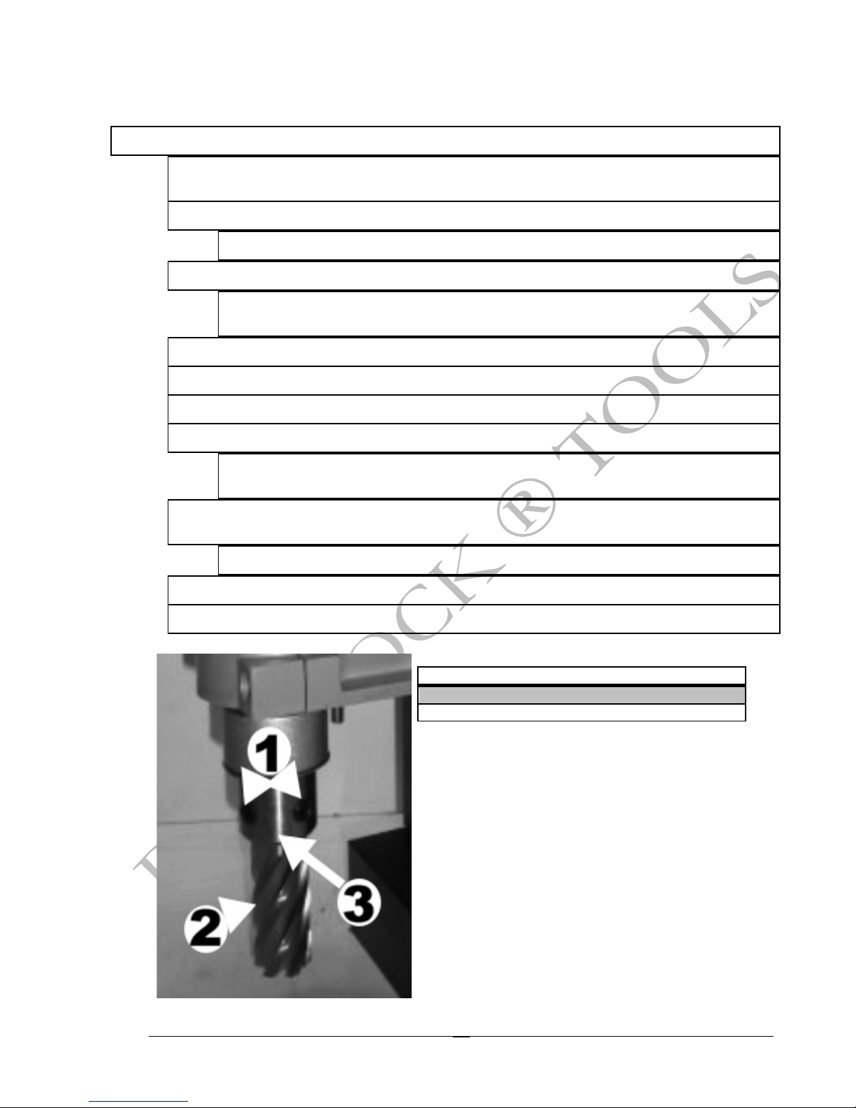
1) ¾” Adapter Hex Set Screws (2 total)
2) Annular Cutter (not included)
3) ¾” Weldon Shank Tool Holder

BRM-35A/B MAG DRILL
11
Troubleshooting
Note
SERVICING SHOULD ONLY BE DONE BY A QUALIFIED TECHNICIAN.
DON’T FORGET TO UNPLUG POWER TO UNIT PRIOR TO SERVICE!
PROBLEM
SOLUTION
Motor does not turn on.
1) Magnet not turned on. Magnet has to be engaged prior to motor
working.
2) Check external power source (extension cord, breaker, etc).
3) Loose internal wire. Check and secure if necessary.
4) Motor brushes defective. Replace if necessary.
5) Check the fuse at the control panel. If it is blown, replace with
same size.
6) Check the back of the internal PC board for a short. Replace if
necessary.
7) Check the relays on the PC board to see if there are any shorts.
Replace if necessary.
8) Check to ensure the motor on/off switch is operable. Replace if
necessary.
Motor turns on when the
magnet is turned on.
1) PC board has a short or relays are fused in closed position.
Check and replace PC board/relay if necessary.
Excessive sparking
when motor is running.
1) This may indicate the presence of debris in the motor or worn out
carbon brushes. Check the brushes for unusual wear and replace
if necessary. Clean out the internal motor armature if necessary.
2) Armature has a rough edge. Inspect and replace if necessary.
Magnetic does not hold
to work area.
1) Work surface thickness is too small. A minimum of 3/8” (10mm)
continuous ferrous steel must be used for magnetic adhesion.
NOTE: It is normal to be able to push these drills off their adhesion
if pushing from the top side. CAUTION: These drills do not work
on sheet metal!
2) Entire magnet base is not on the work surface.
3) Voltage is low at the machine. Check voltage.
4) There is debris or excess material between the work area and the
magnetic base. Clean work area surface.
Hole is not cutting.
1) Cutter is dull. Sharpen or replace.
2) Work area material is not appropriate for cutter type. High carbon
type steels require special cutting bits (tungsten carbide tip, etc).
Chapter
4

BRM-35A/B MAG DRILL
12
General Maintenance
ØInspect electrical cords and electrical connections.
ØKeep machine clean and free of debris.
ØCheck for misalignment, binding and breakage of all moving parts. If damaged, repair tool
before use.
ØKeep cutting tools sharp and clean. Sharp cutters are less likely to bind and are easier to
control.
Occasional Maintenance
ØHave the power tool serviced by a qualified service technician using identical replacement
parts.
oChange motor brushes:
1) Disconnect drill from power.
2) Unscrew left and side brush holder caps.
3) Take out old brushes.
4) Replace with exact same size new brushes.
5) Screw in brush holder caps tightly.
oAdjusting slides:
1) Periodically check, lubricate and adjust slides as necessary.
2) Use hex wrench to loosen the lock nuts and hex screws.
3) Adjust the screws evenly while moving the handle up and down so
that there’s no free play yet not binding anywhere through its range of
travel.
4) Retighten the lock nuts.
Chapter
5

BRM-35A/B MAG DRILL
13
Parts List
Chapter
6
1.
Flexible cable
25.
M6×16 screw
49.
Drill holder plate
73.
Bearing 6004
2.
Magnetic switch
26.
Screw plate
50.
Out slide
74.
Spindle
3.
Fuse cap
27.
Magnetic base
51.
M6×12 screw
75.
Screw M8×8
4.
Fuse
28.
M5 screw nut
52.
Drill holder
76.
Connect
5.
Fuse holder
29.
M5×16 screw
53.
M6×30 screw
77.
Oil holder
6.
Motor starter
30.
Bearing
54.
Brush cap
78.
O ring
7.
Cable protector
31.
Bearing
55.
Brush
79.
Spring
8.
Cable holder
32.
Internal slide
56.
Brush holder
80.
Spring stop
9.
Plate
33.
Slide
57.
M5×65 screw
81.
Catch spring
10.
M4×8 screw
34.
Slide
58.
Motor holder
82.
5mm hex wrench
11.
Handle holder
35.
M5×8 screw
59.
Field core
83.
4mm hex wrench
12.
Handle
36.
Plate
60.
M5×65 screw
84.
Chuck
13.
4×10 key
37.
Rack
61.
Wind catcher
85.
Chuck key
14.
Axle
38.
M6×20 screw
62.
Bearing 6008
86.
Chuck connect
15.
5×15 key
39.
Hook
63.
Motor
87.
Safety strain
16.
Gear
40.
Tank
64.
Bearing 6009
88.
17.
Stop plate
41.
Valve
65.
Gear box cap
89.
18.
Cable protector
42.
M6×10 screw
66.
Bearing 627
90.
19.
Cable holder
43.
Screw plate
67.
Gear
91.
20.
Machine holder
44.
Screw plate
68.
Bearing 627
92.
21.
M5×8 screw
45.
Cable holder
69.
Gear box
93.
22.
Cable fixer
46.
M5×10 screw
70.
Catch spring
94.
23.
M4×10 screw
47.
Screw plate
71.
Gear
95.
24.
Controller
48.
Screw plate
72.
Bearing 6003
96.

BRM-35A/B MAG DRILL
14
Breakdown View
This manual suits for next models
1
Table of contents
Other BLUEROCK Drill manuals


