BlueSens YeastForce User manual

Rev 220301 003
Operating manual
Betriebsanleitung

Rev 220301 003
2
OPERATING MANUAL
EN
Content
1ABOUT THIS DOCUMENT ..............................................................................................3
Purpose.................................................................................................................................... 3
Target group............................................................................................................................. 3
Symbols in use......................................................................................................................... 3
2FOR YOUR SAFETY........................................................................................................4
In general ................................................................................................................................. 4
Authorized personnel ............................................................................................................... 4
Proper and intended usage...................................................................................................... 4
Warning against misuse........................................................................................................... 5
General safety instructions....................................................................................................... 5
CE conformity........................................................................................................................... 5
3PRODUCT DESCRIPTION ..............................................................................................6
The sensor ............................................................................................................................... 6
Converting to a standardized gas ............................................................................................ 6
Accessories.............................................................................................................................. 7
Required laboratory materials.................................................................................................. 8
4INSTALLATION................................................................................................................9
General instructions ................................................................................................................. 9
Attaching the filter adapter ....................................................................................................... 9
5ELECTRICAL CONNECTION ........................................................................................10
In general ............................................................................................................................... 10
USB - RS232 cable wrap-around........................................................................................... 10
RS232 connection to the PC.................................................................................................. 10
6YEASTFORCE MONITOR .............................................................................................12
Installing the software............................................................................................................. 12
Connecting the sensors ......................................................................................................... 14
Search for heads:................................................................................................................... 14
CO2sensor: single-point calibration....................................................................................... 16
Volume inspection.................................................................................................................. 19
Preparing a measurement...................................................................................................... 22
Starting a measurement......................................................................................................... 26
7APPENDIX.....................................................................................................................28
Technical data........................................................................................................................ 28
Warranty................................................................................................................................. 28
Service and Support............................................................................................................... 28
Proper disposal ...................................................................................................................... 29
Imprint .................................................................................................................................... 29
8CE-CONFORMITY.........................................................................................................30
9FCC-CONFORMITY.......................................................................................................31

Rev 220301 003
3
OPERATING MANUAL
EN
1 About this document
Purpose
This operating manual provides you with all the information you need to
quickly commission and safely operate the YeastForce. Please read this op-
erating manual before you start the initial commissioning. Keep this operating
manual in a safe place for future reference.
Target group
This operating manual is intended for trained specialist personnel. The con-
tents of this manual must be provided to and implemented by the trained
personnel.
Symbols in use
Danger!
This symbol indicates a possibly dangerous situation. Failure to
comply with these safety instructions may result in personal in-
jury.
Caution!
This symbol indicates a situation, which could result in damage
to equipment or other property.
Note!
This symbol indicates additional helpful information.
1 Sequence of actions
Sequential numbering indicates successive steps.

Rev 220301 003
4
OPERATING MANUAL
EN
2 For your safety
In general
The YeastForce was inspected before it left the factory and was in an oper-
ationally ready condition.
Please read this operating manual carefully before installing and commis-
sioning the device. The operating manual contains safety instructions that
must be followed to ensure safe operation.
The contents of this manual correspond to the status as of November 2020;
they may be changed without prior notice. We reserve the right to make tech-
nical changes in the course of further developments.
The accuracy of the information in this manual has been carefully checked.
Nevertheless, the BlueSens gas sensor GmbH assumes no liability for con-
sequences arising from any errors in the description and illustrations. The
General Terms and Conditions of BlueSens Gas Sensor GmbH apply.
This device must never be operated under conditions that do not conform to
its specifications and information specified on the ratings plate.
Maintenance and repair may only be carried out by properly trained, compe-
tent personnel who are familiar with the associated risks and warranty provi-
sions.
Authorized personnel
The operations described in this operating manual may only be carried out
by trained specialist personnel who have been authorized by the facility op-
erator. For safety and warranty reasons, any further intervention or repairs
to this device may only be carried out by personnel from BlueSens gas sen-
sor GmbH.
Proper and intended usage
The YeastForce, as described in the Technical Specifications, is a device
for measuring volumetric flows in the specified flow range and under the
specified conditions. It is used to monitor metabolic procedures within bio-
logical processes. The YeastForce measuring device may only be used in
well-ventilated rooms.

Rev 220301 003
5
OPERATING MANUAL
EN
Danger!
This measuring device has no ATEX approval and may only be used
in well-ventilated rooms.
Warning against misuse
The YeastForce may not be used as a safety component for monitoring in
facilities; it must not be used in explosive zones.
General safety instructions
This device may pose application-specific hazards if it is used improperly.
Danger!
Incorrect installation or configuration may result in an explosion.
Check all connections for leaks after the installation is finished.
CE conformity
The YeastForce complies with the EMC Directive (2014/30/EU) using the
harmonized standards EN 55011, EN 61326-1.
The Low Voltage Directive (2014/35/EU) does not apply because no voltage
higher than 24 V is used.
See the last pages of this manual for the CE and the FCC certificate.

Rev 220301 003
6
OPERATING MANUAL
EN
3 Product description
The sensor
The YeastForce consists of a sensor top section [A]
(with sensors for pressure, CO2concentration and
temperature) and a lower section consisting of a jar
[B] with one bracket [C].
There are two connectors on the top of the
YeastForce. One connection is used for the power
supply and communications [D]. The other connec-
tion is used for the gas discharge [E]. A filter is in-
cluded for the gas discharge.
Figure 1
During operations, the filter must be mounted at the gas discharge outlet.
Otherwise, the pressure cannot be released from the sensor.
This would prevent the sensor from functioning correctly; dangerous over-
pressure could then occur.
To achieve the best measurement result, the
YeastForce should be operated in a bath of water at
a constant temperature while measuring. The water
level must not be higher than the glass jar.
Converting to a standardized gas
The YeastForce has sensors for pressure and tem-
perature. With the help of these measured values,
the internally calculated volume is normalized to the
standard conditions of 1013.25 mbar and 273.15 K
(0°C).
The calculation can be converted back to any labor-
atory conditions by using the general gas equation.
Since the number of particles in a closed system is
constant, the following formula applies:
𝑝 ∗ 𝑉
𝑇= 𝑐𝑜𝑛𝑠𝑡𝑎𝑛𝑡
where 𝑝 = 𝑃𝑟𝑒𝑠𝑠𝑢𝑟𝑒 [𝑚𝑏𝑎𝑟]
𝑉 = 𝑉𝑜𝑙𝑢𝑚𝑒 [𝑚𝑙]
𝑇 = 𝑇𝑒𝑚𝑝𝑒𝑟𝑎𝑡𝑢𝑟𝑒 [𝐾]
In the template settings of the YeastForce Monitor,
you can set the standard conditions for the tempera-
ture to easily compare it with other measuring meth-
ods according to user requirements.

Rev 220301 003
7
OPERATING MANUAL
EN
Accessories
The following accessories are required for the ini-
tial commissioning of the YeastForce:
3.3.1 USB RS232 serial port adapter with
power supply connection
(Z-KA-00014)
With wrap-around (refer to chapter 5.2)
Figure 2. Connection from the PC (USB) to the
YeastForce (M12 / 8-pin)
3.3.2 12 V DC power supply
(Z-NT-00010)
Figure 3. 12 V DC power supply
3.3.3 Glass jar for the YeastForce
Standard empty volume of 562.5 ml (± 2
ml)
(Z-GF-00019)
Figure 4 Glass jar for the YeastForce
3.3.4 Bracket for the YeastForce
(Z-XX-00166)
Figure 5 Bracket
3.3.5 Filter adapter for the YeastForce gas
discharge
(Z-XX-00133)
Figure 6 Filter adapter

Rev 220301 003
8
OPERATING MANUAL
EN
3.3.6 Piston pump for volume inspection (20
ml)
(Z-XX-00134)
Figure 7 Piston pump
3.3.7 Active USB hub
Optional
(K-00006)
Figure 8 Active USB hub
3.3.8 Seal ring
(Z-XX-00200)
Figure 9 Seal Ring
Required laboratory materials
3.4.1 Sodium hydroxide NaOH
For removing residual CO2during the single-point
calibration of the CO2sensor
Available from chemical specialty stores
3.4.2 Water bath
The sensor is calibrated to a temperature range of
15-40°C. Therefore the water bath may have a tem-
perature range of 25-40°C.
Water height: 5 –9 cm (maximum height of glass
jar)
The YeastForce must not be completely im-
mersed because it has a protection class of IP64!
Rev 220301 003
9
OPERATING MANUAL
EN
4 Installation
General instructions
During delivery, the YeastForce has been shipped in
protective packaging. This packaging protects
against normal transport loads. Nevertheless, please
check before installation whether the device has
been damaged by improper transport or improper
storage. Safe operation is not possible if the device
is damaged. The device may not be installed or put
into operation if damage is detected.
Make sure that the specified operating conditions are
maintained at all times.
Installation should only be carried out under expert
guidance and in accordance with the relevant recog-
nized occupational safety regulations.
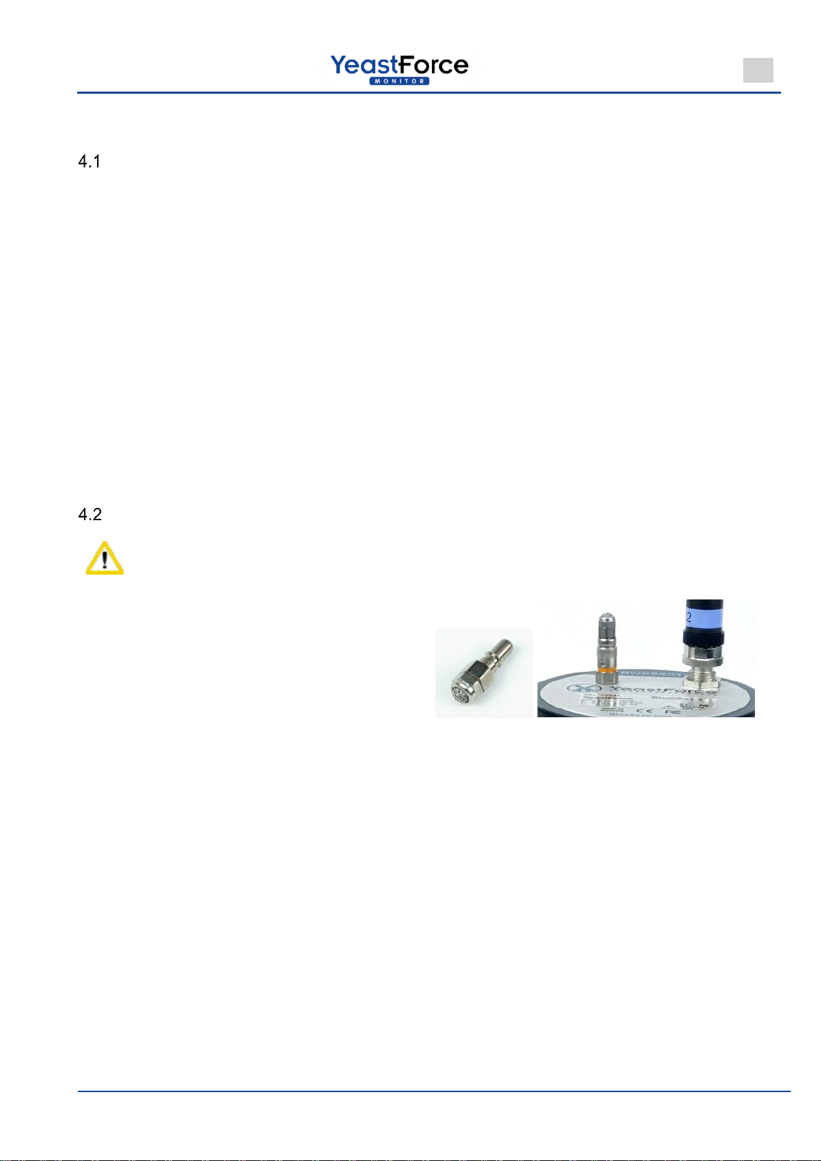
Attaching the filter adapter
Important!
If the sensor is supplied without a filter adapter on
the gas discharge, the filter adapter must be at-
tached to the gas discharge after unpacking the
YeastForce sensors.
Figure 10 Attaching the filter adapter
Rev 220301 003
10
OPERATING MANUAL
EN
5 Electrical connection
In general
Caution!
Read the installation instructions carefully to
avoid damaging this device.
Proceed step by step.
Use only the original plugs, cables and power
supplies.
Never connect or disconnect the plug when
the device is connected to the power supply.
This device has no on/off switch. It starts op-
erating immediately after it is connected to the
power supply.
Incorrect operations may damage the device.
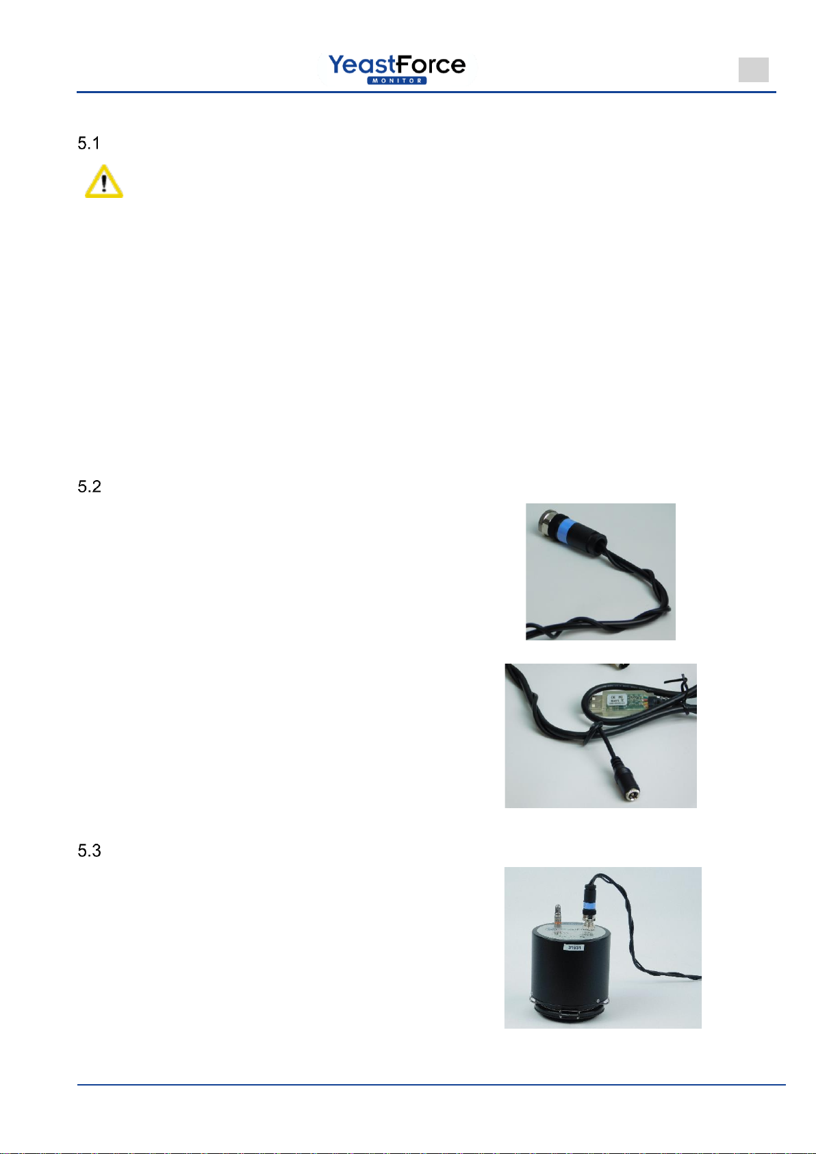
USB - RS232 cable wrap-around
To minimize the risk that the YeastForce cable
tangles with any other cables, the power supply
cable should be wrapped around the data cable. A
simple method is to wrap the power supply cable
around the data cable.
First, wrap the data cable around the M12 8-pin
connector. Continue until the power supply cable
is completely wrapped around the data cable.
Figure 11 Wrapping the cables
At the end, make a small loop and form the cable
into a knot. This prevents the power cable from un-
winding.
Figure 12 Knot the cables at the end
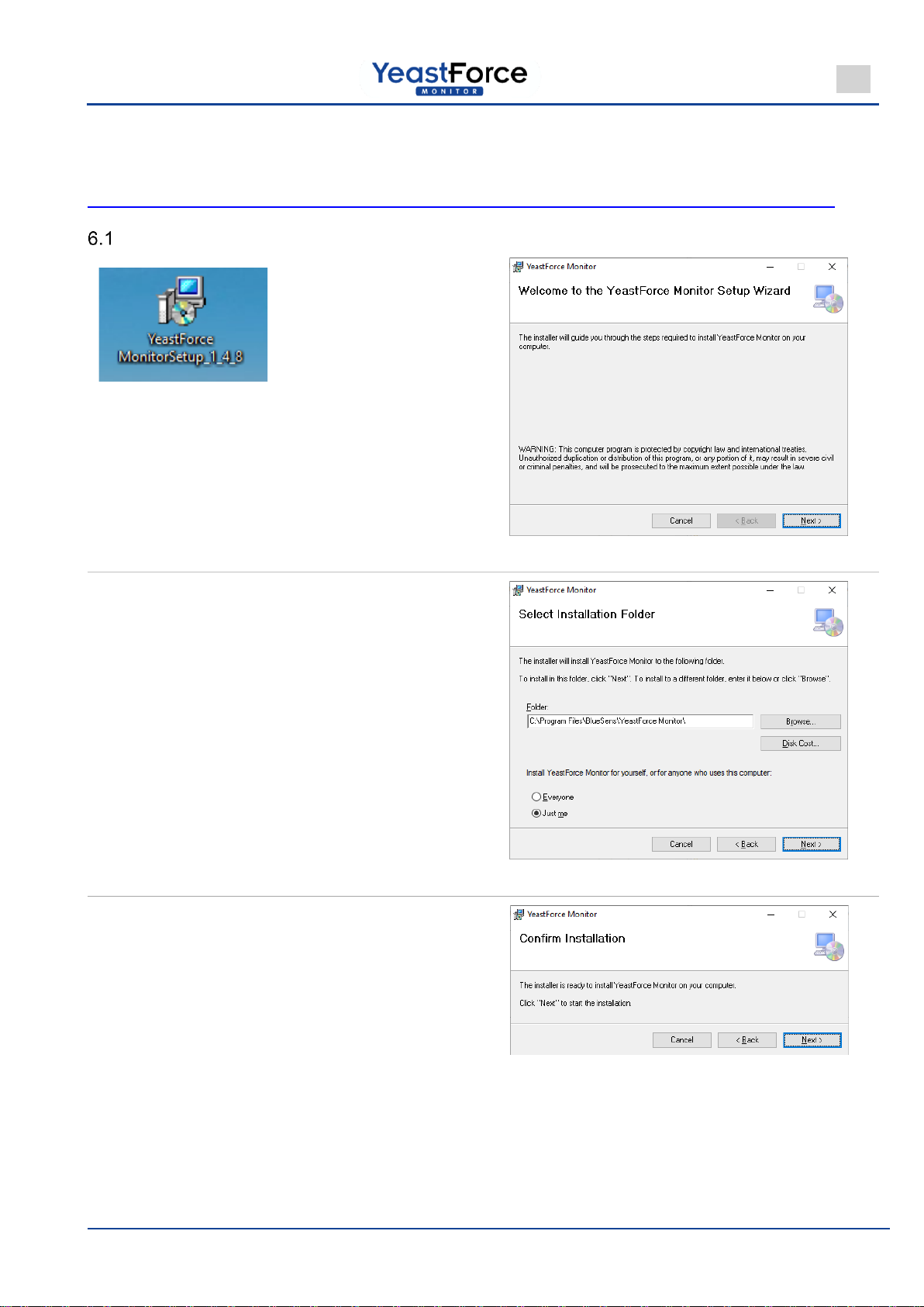
RS232 connection to the PC
The USB-to-RS232 cable (with power supply) is
first attached to the YeastForce using the M12 8-
pin adapter.
The plug of the power supply unit is then connected
to the power connection of the data cable and se-
cured so that it cannot slip out.
Figure 13

Rev 220301 003
11
OPERATING MANUAL
EN
The power supply unit may now be plugged into a
power outlet. Now, the sensor starts working.
The cable's USB plug should now be connected to
a computer (in an active hub if necessary).
Figure 14
The sensor needs about one hour un-
til it is ready for operations. No meas-
urement may be made before this.
The YeastForce Monitor program shows a flash-
ing icon during this warm-up period:
[Wait while sensor heats up]
Figure 15
Rev 220301 003
12
OPERATING MANUAL
EN
6 YeastForce Monitor
You can download the latest software at the following link:
https://www.bluesens.com/fileadmin/user_upload/downloads/YeastForceMonitorSetup_1_4_20.msi
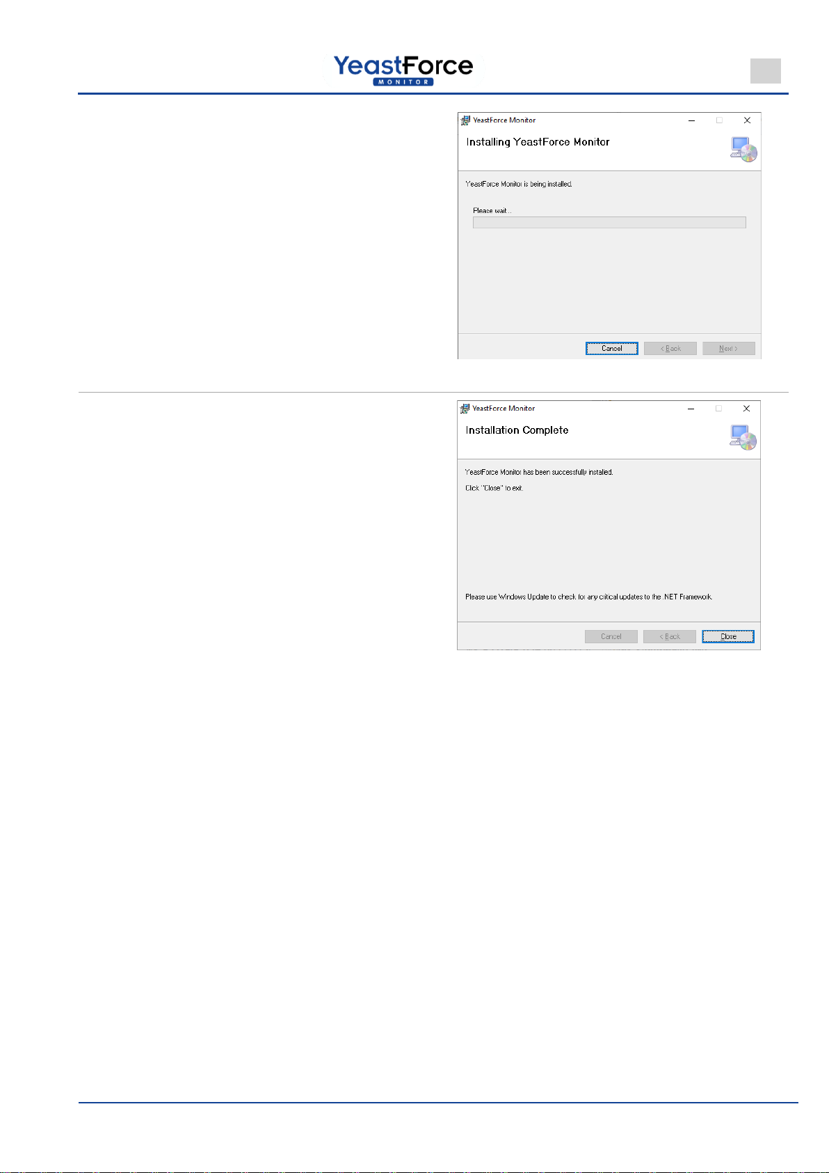
Installing the software
Double-click on the .msi file to start the installa-
tion. Since the program is installed in the Program
Files folder, admin rights are required during in-
stallation.
The Welcome page appears.
Click on [Next]
Figure 16
Select the installation path and user settings.
Click on [Next]
Figure 17
Confirm and start the installation:
Click on [Next]
Figure 18
Rev 220301 003
13
OPERATING MANUAL
EN
The program is installed:
Please wait:
A progress bar shows the
installation progress.
Figure 19
The final dialogue box appears after a successful
installation:
Click on [Close]
Figure 20

Rev 220301 003
14
OPERATING MANUAL
EN
Connecting the sensors
If the drivers are not found automatically, you can
download the latest FTDI-VCP driver from the follow-
ing page:
https://www.ftdichip.com/Drivers/VCP.htm
Search for heads:
Figure 21 YeastForce Monitor, after the program start
When the program is started, all available COM
ports in the computer are scanned for connected
sensors. These are then loaded into the program.
If not all sensors are found, the program can
search for more sensors again via the
[HeadsSearch Heads] option.
Figure 22
If a found sensor is then disconnected and recon-
nected to the computer, it can be reactivated with
the [Reconnect] option.
Figure 23

Rev 220301 003
15
OPERATING MANUAL
EN
6.3.1 Configuring a sensor head
To configure the YeastForce sensor, the
Configuration window can be invoked from
the [Heads] menu or the [HeadInfo] right-
click context menu.
Figure 24
Use the [Custom Head Color] drop-down
list to change the display colour of the sen-
sor.
The [Show Always] option causes the sen-
sor to always be displayed on the user in-
terface. If the sensor is not found, this is
displayed immediately. You can reactivate
the sensor in the program's context menu
via [Reconnect].
Figure 25
If the [Show Export Options / Calibration]
option is selected, additional information
about the sensor is displayed.
This calibration information relates to the
data about the operating status saved in
the sensor or the program. If the single-
point calibration or volume inspection was
performed more than one month ago, it
must be carried out again. The previous
dates (of last execution) are displayed in
this window.
Figure 26

Rev 220301 003
16
OPERATING MANUAL
EN
CO2sensor: single-point calibration
CO2absorber NaOH
Danger!
NaOH may only be used in accord-
ance with the applicable safety pre-
cautions!
Serious injury to skin
or eyes
Wear protective gloves
Wear safety goggles
Gather the materials together:
- YeastForce sensor
- Glass jar for the YeastForce
- NaOH solution (e.g. 3 M ~= 10 %)
- Small vessel for at least 20 ml NaOH (e.g.
100 ml beaker),
which will fit into the glass jar
Figure 27
Pour 20 to 100 ml NaOH into a suitable vessel and
place it in the glass jar.
Figure 28
Attach the YeastForce to the jar using the bracket
on the glass jar.
Figure 29

Rev 220301 003
17
OPERATING MANUAL
EN
Startthe single-pointcalibrationinthe YeastForce
Monitor (via the right-click context menu for the
sensor and confirm the information about the ad-
dition of NaOH by clicking on OK).
Figure 30
The concentration is then recorded for 5 minutes
and the slope of the graph is displayed. The upper
graph shows the progress over the entire time of
the measurement. The lower graph always shows
only the last five minutes. The slope of the graph
is also calculated during these five minutes.
Figure 31
The CO2concentration now decreases until there
are hardly any CO2molecules left in the vessel. If
the slope drops below 2 ppm/min, the button for
the single-point is enabled.
Figure 32
After the single-point calibration is finished, the
new concentration for the sensor is displayed. If
this is more than 0.01% by volume, the single-
point calibration should be performed again.
Figure 33

Rev 220301 003
18
OPERATING MANUAL
EN
Click on the Restart button: the instrument waits
again for 5 minutes until a new single-point cali-
bration is possible.
Also here, the slope must be less than 2 ppm/min.
Figure 34
You can click on the [Return to YeastForce Moni-
tor] button to return to the main program.
Figure 35
Rev 220301 003
19
OPERATING MANUAL
EN
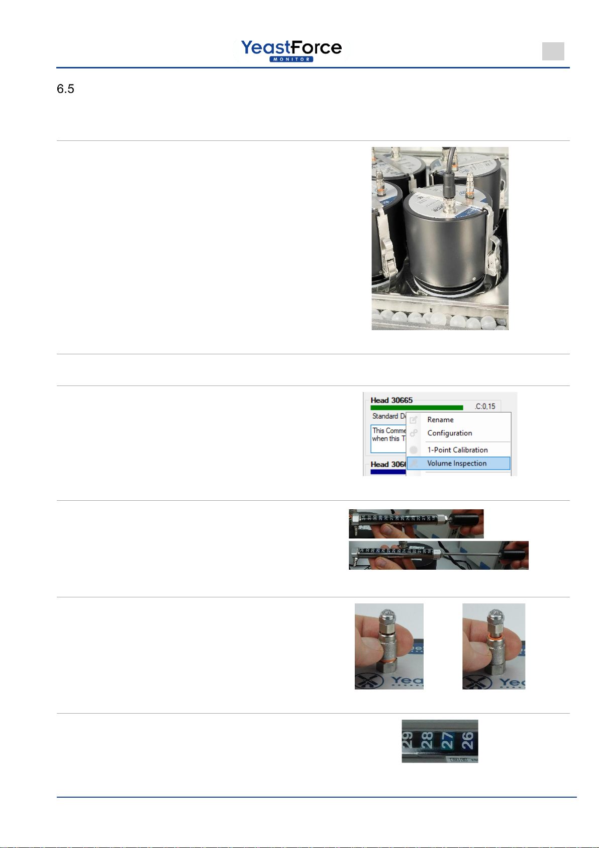
Volume inspection
Connect the sensor to the power supply. Connect
the USB cable to the computer.
(Refer to chapter 5)
Mount the YeastForce on a glass jar. Place them
together in a water bath with a water height be-
tween 5 and 9 cm.
The temperature in the water bath should be be-
tween 25 and 40 °C, and higher than room tem-
perature.
Keep the water bath and sensor at a constant
temperature for at least 30 minutes.
Figure 36
Start the YeastForce Monitor software program
and search for the connected YeastForce head.
(Refer to chapter 6.3 Search for heads)
Start a volume inspection from the right-click con-
text menu.
Figure 37
Pull out the piston pump.
Figure 38
Remove the YeastForce's protective filter by
pushing the fluted ring down towards the orange
band.
Figure 39
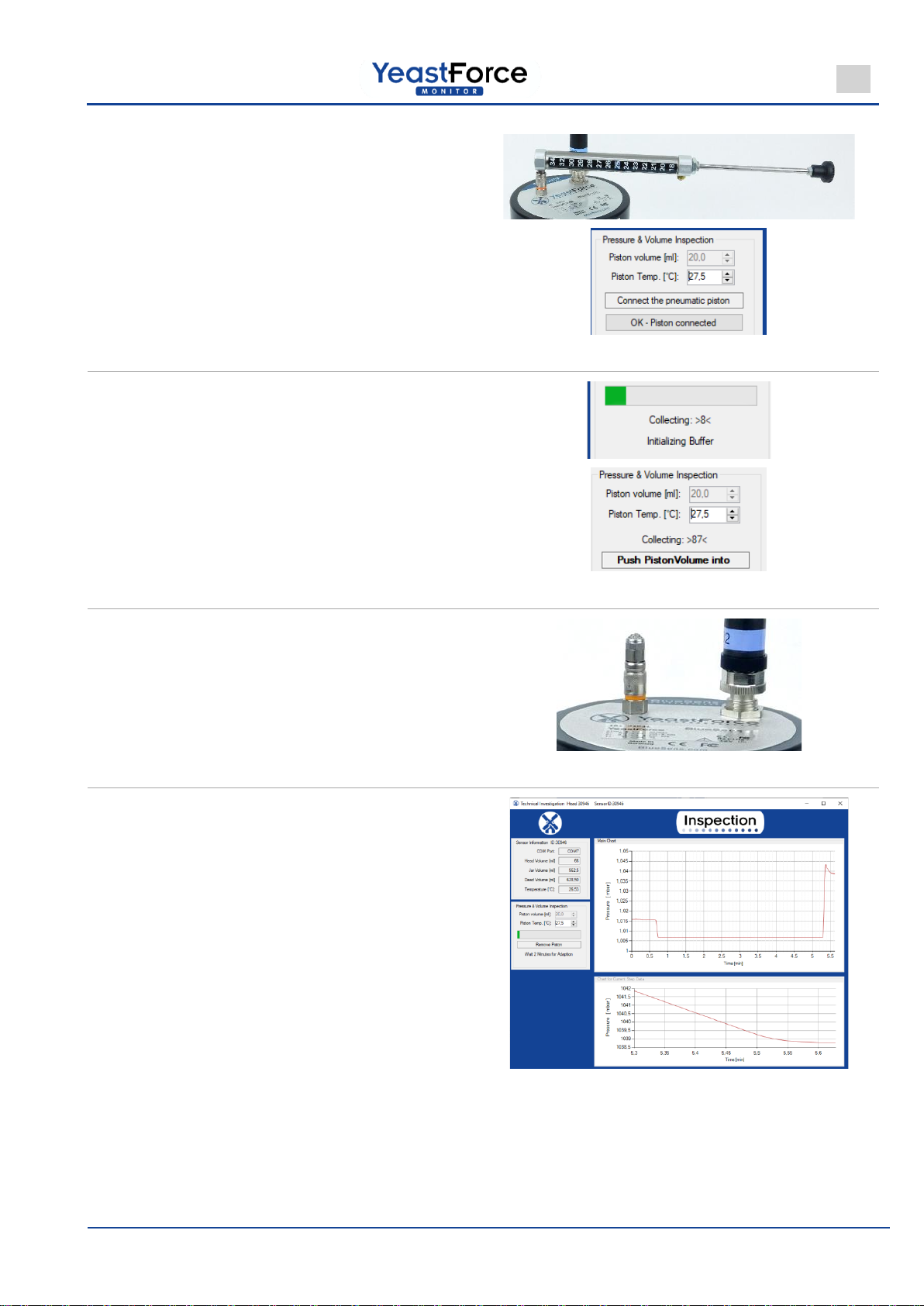
Enter the temperature of the piston in the pro-
gram. (here: 27.5°C)
If it is too cold, heat the piston to 20°C with your
hands.
Figure 40
Rev 220301 003
20
OPERATING MANUAL
EN
Place the piston pump on the YeastForce until
the piston clicks into place.
Then, confirm this in the program:
[OK –Piston connected]
Figure 41
Wait about 10 seconds.
If the pressure is constant and the program
prompts you to do so, press the piston rod into the
piston slowly and consistently.
Figure 42
After the valve closes (audible soft click and the
message [Remove Piston]), the piston can be re-
moved and the filter can be put on.
Figure 43
The pressure rises in the YeastForce.
The program records the pressure and calculates
the tightness and volume of the system.
The lower graph shows a partial section of the up-
per graph.
This automatically displays the relevant part of the
measurement with more details.
Figure 44
Table of contents
Languages:


