Blueworks BLSC User manual

BLSC

1
Table of Contents
IMPORTANT SAFETY INSTRUCTIONS:.................................... 2
INTRODUCTION:......................................................................... 3
SYSTEM OVERVIEW:................................................................. 4
WATER CHEMISTRY: ................................................................. 5
ADDING SALT/SALT LEVEL:...................................................... 6
INSTALL CELL:............................................................................ 9
INSTALL CONTROL:..................................................................11
WIRING...................................................................................... 12
INSTALLATION CHECKLIST:.................................................... 16
INITIAL START UP:.................................................................... 16
OPERATION:............................................................................. 17
GENERAL MAINTENANCE:...................................................... 21
WINTERIZING: .......................................................................... 23
HELPFUL NOTES:..................................................................... 24
TROUBLESHOOTING............................................................... 25
WARRANTY............................................................................... 28
BLSC LABEL.............................................................................. 30
BLSC CELL REPLACEMENT LABEL ....................................... 31

2
BLUEWORKS BLSC
GENERATOR GENERATOR
Installation and Operation Manual
For BLSC
IMPORTANT SAFETY INSTRUCTIONS
When using electrical equipment, basic safety precautions should
always be exercised, including the following:
READ AND FOLLOW ALL INSTRUCTIONS
Disconnect all AC power during installation.
Do not permit children to use this product.
Agreen colored screw is located inside the wiring compartment,
against the back panel. To reduce the risk of electric shock, this
terminal must be connected to the grounding means provided in
the electric supply service panel with a continuous copper wire
equivalent in size to the circuit conductors supplying the
equipment.
One bonding lug for US models (two for Canadian models) is
provided on the external surface. To reduce the risk of electric
shock, connect the local common bonding grid in the area of
the swimming pool, spa, or hot tub to these terminals with an

3
insulated or bare copper conductor not smaller than 8 AWG
US/6AWG Canada.
All field-installed metal components such as rails, ladders,
drains, or other similar hardware located within 10 feet (3
meters) of the pool, spa or hot tub shall be bonded to the
equipment grounding bus with copper conductors not smaller
than 8 AWG US/ 6 AWG Canada.
Introduction:
The BLSC chlorine generator, by electrolysis, creates chlorine to
sanitize your pool from the salt molecules (NaCL) in your water. A
small electric charge is applied across a set of titanium plates inside
the Electrolytic Cell. This produces Sodium Hypochlorite (NaOCl). In
water, Sodium Hypochlorite dissociates into sodium (NA+) and
hypochlorite (OCl-) ions. It is the hypochlorite ions that form with the
hydrogen (H+) ions (from the water) to form hypochlorous acid
(HOCl), which is the active agent that destroys bacteria and algae,
and oxidizes organic matter. This form of chlorine works quickly in
the pipe, leaving only a mild residual in the pool. In addition, the
Electrolytic Cell continuously“shocks”the incoming water- burning
off any oils, organic matter, or other particles that need to be
oxidized.
Best of all, the process continuously recycles the salt: after cleaning
the pool, the original molecules reform and the whole process
begins again. The salt doesn't get used up!
4
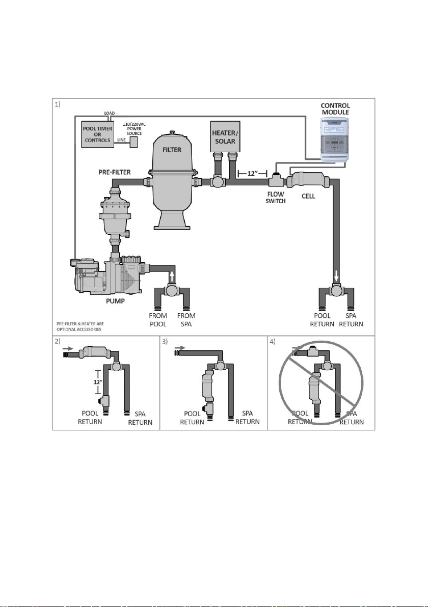
System Overview :
There are three main Parts to BLSC system: the Control Unit, the Electrolytic Cell, and
the Flow Switch.
Control Unit: Supplies power to the cell and allows you customize the system's operation,
in order to meet your pool's unique needs.

5
Electrolytic Cell: Creates chlorine as the water inside passes through and returns to the
pool. The Electrolytic Cell ("Cell") contains a number of titanium plates that use a lowlevel
of electrical power to generate chlorine from salt in the water. The Cell comes with Unions
to connect to the plumbing; each Union has a Threaded Collar that secures the Cell to the
Unions, and enables the Cell to be easily removed for cleaning and inspection purposes.
Flow Switch: This component detect the water flow in pipe and protect the system.
WATER CHEMISTRY:
As with any pool, it is important that you maintain proper water chemistry of the pool water,
including pH, alkaline content, and calcium levels. The only special requirement for BLSC
is to maintain proper levels of salt and stabilizer. It is important to maintain these levels in
order to prevent corrosion or scaling and to ensure maximum enjoyment of the pool. Test
your water periodically. It is recommended that pool water be professionally tested a
minimum of twice per season. Your local pool store can provide you with the chemicals
and procedures to adjust the water chemistry. Be sure to tell the pool store that you are
using a salt chlorine generator.
IDEAL CHEMICAL LEVELS
Swimming Pools
Spas
Free chlorine
1.0 to 3.0 ppm
3.0 to 5.0 ppm
Salinity
3000 to 4000 ppm
3000 to 4000 ppm
pH
7.2 to 7.8
7.2 to 7.8
Cyanuric Acid (Stabilizer)
60 to 80 ppm
60 to 80 ppm
Total Alkalinity
80 to 120 ppm
80 to 120 ppm
Calcium Hardness
200 to 400 ppm
150 to 450 ppm
Saturation Index
-0.2 to 0.2
-0.2 to 0.2

6
Adding Salt:
IMPORTANT: Before adding salt, ALWAYS perform an independent water test to measure
pre-existing salt levels.
Use only evaporated, granulated, non-iodized salt (Sodium Chloride). The purer the salt
(at least 99%), the better the life and performance of the Electrolytic Cell.
DO NOT add chemicals or salt directly to the skimmer. This may damage the cell. If the
Electrolytic Cell has already been installed, it should not be turned on before adding salt.
For pools, it is best to empty the required salt into the shallow end of the pool and run the
filter and pump simultaneously in order to circulate the water and dissolve the salt (the is
to remain off during this time period). Do not throw the salt bag into the water as
chemicals and inks on the bag can interfere with water balance. Salt may take 24 - 48
hours to dissolve in summer, and longer in winter. Finer granules of salt will dissolve
faster than compressed pellets.
Water Softener salt (also known as Water Conditioning pellets) is an economical way to
buy large quantities of salt. However, only salt that is at least 99% pure NaCl can be used.
Pellets are compressed forms of evaporated salt that may take longer to dissolve. Avoid
using salt with anti- caking agents (Sodium Ferrocyanide, also known as YPS or Yellow
Prussiate of Soda) that could cause discoloration of fittings and surface finishes in pool.
Do not use Calcium Chloride as a source of salt. Do not use Rock Salt; insoluble
impurities mixed with the rock salt can shorten the life of the unit.

7
Salt Levels:
The system can work within a broad salinity range, from a minimum of 3000 ppm (parts
per million), up to 4000 ppm. However, the ideal level for operation is about 3400 ppm. To
achieve this level of salinity, add approximately 30 lbs of salt for every 1000 gallons of
water (or 3.4 Kilograms of salt for every 1000 Liters). If you are unsure of the number of
gallons in your pool, double-check with the following equations.
Notice: When adding large quantities of salt, start with an independent test of the existing
salinity level and add in portions, retesting at each stage.
Calculating Gallons (Measurements in Feet)
Rectangular -Length x Width x Average Depth x 7.5
Round -Diameter x Diameter x Average Depth x
5.9
Oval -Length x Width x Average Depth x 6.7
Before adding salt, check your water for any existing salt content and add according to
the chart below. If too little salt is added, the result will be reduced efficiency and a low
level of chlorine production. In addition, operation at low salt levels will reduce the
longevity of the cell. The salt in your pool is constantly recycled, and the loss of salt
throughout the swimming season should be small. This loss is due primarily to the
addition of extra water to replace water lost from splashing, backwashing, and draining.
Salt is not lost due to evaporation.

8
POUNDS and (Kg) OF SALT NEEDED FOR 3400 PPM Gallons and (Liters) of
Pool/Spa water
Current
salt level
ppm
6,000 8,000 10,000 12,000 14,000 16,000 18,000
(22,500) (30,000) (37,500) (45,000) (52,500) (60,000) (67,500)
0
180
(82)
239
(109)
301
(136)
360
(163)
419
(190)
481
(218)
540
(245)
200
170
(78)
226
(103)
284
(129)
340
(154)
396
(180)
454
(206)
510
(232)
400
160
(73)
213
(97)
267
(121)
320
(145)
373
(170)
427
(194)
480
(218)
600
150
(69)
200
(91)
250
(114)
300
(136)
350
(159)
400
(182)
450
(205)
800
140
(64)
187
(85)
233
(106)
280
(127)
327
(148)
373
(170)
420
(191)
1000
130
(59)
173
(79)
217
(98)
260
(118)
303
(138)
347
(158)
390
(177)
1200
120
(55)
160
(73)
200
(91)
240
(109)
280
(127)
320
(145)
360
(164)
1400
110
(51)
147
(67)
183
(83)
220
(100)
257
(117)
293
(133)
330
(150)
1600
100
(46)
133
(61)
167
(76)
200
(91)
233
(106)
267
(121)
300
(136)
1800
90
(41)
120
(55)
150
(68)
180
(82)
210
(95)
240
(109)
270
(123)
2000
80
(36)
107
(48)
133
(61)
160
(73)
187
(85)
213
(97)
240
(109)
2200
70
(32)
93
(42)
117
(53)
140
(64)
163
(74)
187
(85)
210
(95)
2400
60
(27)
80
(36)
100
(45)
120
(55)
140
(64)
160
(73)
180
(82)
2600
50
(23)
67
(30)
83
(38)
100
(45)
117
(53)
133
(61)
150
(68)
2800
40
(18)
53
(24)
67
(30)
80
(36)
93
(42)
107
(48)
120
(55)
3000
OK
OK
OK
OK
OK
OK
OK
3200
OK
OK
OK
OK
OK
OK
OK
3400
Ideal
Ideal
Ideal
Ideal
Ideal
Ideal
Ideal
3600
OK
OK
OK
OK
OK
OK
OK
3800
OK
OK
OK
OK
OK
OK
OK
4000
OK
OK
OK
OK
OK
OK
OK
4200
High
High
High
High
High
High
High
4400
Dilute
Dilute
Dilute
Dilute
Dilute
Dilute
Dilute

9
Install cell:
Install using the unions provided. Tighten by HAND for a watertight seal. For pool/spa
combination systems with spillover, refer to the above Overview to allow chlorination for
both the pool and spa during spillover but preventing over chlorination when operating the
spa only. For proper plumbing, refer to the overview diagram on page 4. NOTE: The
following are basic plumbing instructions for the typical installation, which entail
positioning the Flow Switch and Cell adjacent to each other on 2" plumbing. Your
installation may vary depending on space available and your specific arrangement of
equipment. IMPORTANT: Ensure that the pool pump and all AC power is turned off before
installation.
Flow switch:
IMPORTANT: To insure proper operation, verify that the arrow on the flow switch (located
on the side) points in the same direction of water flow.
The Flow Switch and Cell are to be fitted into the return line as the last pieces of
equipment the water passes through before returning to the pool: always after the pump,
filter, heater (if applicable), etc. If a heater is present, all equipment must be a minimum
distance away, per heater manufacturer recommendations.
Lay out your equipment to ensure there is enough pipe space available.
When positioning the Flow Switch, ensure at least 6 to 12”(30cm) of straight pipe
before the Flow Switch. If installed after the Electrolytic Cell, the Cell provides this
space. The raised arrow on the black plastic cap must be pointed with the direction
of water flow as it returns to the pool. If installed horizontally, ensure that the
wire-side faces upwards. The Flow Switch is approximately 4" in length; the typical
gap required is 1 ¼".
When positioning the Cell, you can consider the side of the cell with the cord the

10
"inlet" side. If installed horizontally, ensure that the wire- side faces upwards. From
end to end, the Cell with both Unions is approximately 15 ¾" in length; the typical
gap required is 13 ¼".
Refer to the overview diagram on page 4 for alternate configurations. For combined pool
and spa systems with a spillover, allow chlorination for both the pool and spa during
spillover but preventing possible over-chlorination when operating the spa only. Vertical
Installation Kits are also available to minimize plumbing space required and increase
ease of installation.
TIP: Double-check that all Cell and Flow Switch cables can reach the Control Panel.
Note: For installations with 1 ½" plumbing, use 2" to 1 ½" reducer bushings with flow
switch, and use alternate 1 ½" Cell Unions; be sure to note any new or additional
measurements before cutting pipe.
After determining the section of plumbing to install the Flow Switch and Cell, measure out
and mark the selected area.
1. To install the Flow Switch, cut out a section of pipe at the desired installation
location. Use PVC Primer to clean and prepare the pipe ends and interior of Flow
Switch. Using plumbing Solvent Cement, glue the Flow Switch to the pipe ends.
Ensure excess glue does not become affixed to movable parts within Flow Switch.
IMPORTANT: To insure proper operation, verify that the arrow on the flow switch
(located on the black plastic) points in the direction of water flow; the water flow
must depress the hinged activator inside of the Flow Switch. This portion is
threaded and may be turned during service; additional thread seal tape may be
added if necessary.

11
2. To install the Cell Unions, cut out a section of pipe at the desired installation location.
Clean parts and plumbing with PVC Primer to prepare the pipe ends and interior of
Unions. Place the Threaded Collars over the pipe ends. Using plumbing Solvent
Cement, glue one Union to the pipe end.
3. Hold the Cell and second Union up to the first, to gauge the correct distance before
gluing the second Union to the remaining pipe end. Allow sufficient time for glue to
dry.
Ensure that the O-rings are fitted to the Unions. Place the Electrolytic Cell between the
Unions and tighten the Collars onto the Cell. For a watertight seal, do not over-tighten the
Collars, and only tighten them by hand.
When using a Variable-Speed or Multi-Speed pump on a low speed setting, the cell
should be inverted in order to ensure adequate flow & efficient chlorine production.
Install Control Unit:
The BLSC control must be mounted a minimum of 5 ft. (2 meters) horizontal distance (or
more if local codes require) from the pool/spa. The control is designed to mount vertically
on a flat surface facing downward. Because back of enclosure also acts as a heat sink
(disperses heat from inside the box), it is important not to block the back sides of the
control.
Overview: Using screws, secure the Control unit mounting at a comfortable level on a
wall or vertical support, at least 3 feet above ground level. Minimize direct exposure to
rain, sunlight, water runoff, and lawn sprinkler systems. As with most electronics, avoid
placing the controls in tightly enclosed spaces to avoid a build-up of excess heat. For

12
operation, the Control Unit may be wired in to the pump's power source so that both turn
on and off together, or energized continuously for use with variable speed pumps (Flow
switch will control Cell power but lights will remain on).
Notice: Do not operate unit until all salt is dissolved in pool water
Wiring:
Power must be shut off at the circuit breaker before performing any wiring. Be sure to
follow local and NEC/CEC electrical codes. The system has been designed to easily wire
into typical in- ground pool systems. To provide safe operation, the unit must be properly
grounded and bonded.
Bonding:
A lug used for bonding is attached to the bottom of the Control Unit. The Control Unit
must be bonded with an 8AWG copper wire to the pool bonding system.
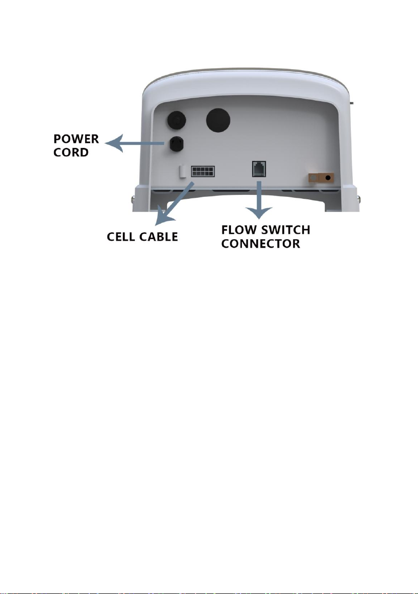
Electrolytic Cell and Flow Switch Connections:
The Cell and Flow Switch cables have easy plug-in connectors, which attach easily to
the Control Unit. Refer to the diagram below for the location of these connections.
13
Wiring to Power Source:
The Control Unit comes with an un-terminated Power Cord (AC Input) which is typically
connected to an external timer, which will turn the pump and Control Unit on and off
together. Have the Control Unit wired to the load side of the timer by a qualified person.
See the following diagram for typical wiring. See voltage warning on page 15.
The is shipped from the factory with a 240 VAC configuration. If 120 VAC is needed, move
the internal jumpers as shown on page 15. If unsure, seek professional advice.
When used with variable-speed or other electronically controlled pumps, you may wish to
wire the Control Unit directly to your power source. This will allow the pump to determine
when the Cell is energized or dormant by activation of the Flow Switch.
Always double-check the voltage of your power source. Connection to improper voltage
can: a) cause severe damage/harm, or b) cause lights and screen to power on without
system function.

14
In some parts of the United States and Canada, the Control Unit must be connected to a
circuit protected by a Class A ground fault interrupter (GFI). Check local codes before
connecting.
At this point, this installation of your equipment is complete. If the water has not yet been
prepared, then you are ready to begin adding salt and balancing your water chemistry.
Turn to Control Unit to the Power Off mode until enough salt has been added to the water.
The following information will give you more information about the process of adding salt.
Be sure to familiarize yourself with your pool's ideal chemistry levels, which play a critical
role in the operation and longevity of your pool and pool equipment.
VOLTAGE CONVERSION:
Always double-check the voltage of your power source. Connection to improper voltage
can: a) cause severe damage/harm, or b) cause lights and screen to power on without

15
system function.
All service should only be attempted by a person with appropriate electrical skills, with all
equipment disconnected from power.
The is shipped from the factory with a 240 VAC configuration. If 120VAC is needed, move
the internal jumpers as shown below. If unsure, seek professional advice.
This set of terminal screws can be located inside of the Control Unit, and accessed by
removing the four screws from the Control Unit's aluminum base. The factory voltage
setting is the 240V configuration, with a jumper clip inserted between the second and third
terminals. The Control Unit can be made to accept 110V by reconfiguring the jumper clips
as shown above left, with two jumper clips instead connecting the first and second
terminals, and the third and fourth terminals.

16
INSTALLATION CHECKLIST:
□Cell Unions installed and glued into pipe work.
□Threaded Collars on either side of the Cell are hand tight.
□Flow Switch is installed and oriented properly.
□Control Unit is affixed to wall and wired correctly.
□Cell Cable and Flow Switch are connected to Control Unit.
□You have checked and confirmed that Control Unit switches ON and OFF concurrently
with filter pump, or is energized continuously for use with variable speed pump.
□You have checked all connections and joints for leaks.
□Sufficient salt has been added and fully dissolved and circulated throughout pool water.
□Pool has properly balanced water chemistry.
Initial Start Up:
Once installation is complete, ensure that the added salt has been fully dissolved in the
pool, and that the pool is clean and chemically balanced.
Apply power to the pool pump switch (or timer controls). This should activate the system,
and within moments the green LED lights for "Power" and "Generating" should be
illuminated. During this time, you may also see the "No-Flow" light flash for up to 60
seconds as your pump begins its operation.
To find the optimum Chlorine Output setting, start at a setting of 70% and adjust as
needed over the initial start up period. Measure your available chlorine in the pool after
two to three days, and adjust the Chlorine Output level accordingly. If the available
chlorine is too high, lower the Output level; if the available chlorine is too low, raise the
Output level. It will take a few adjustments to find the ideal setting for your pool. Once
determined, it should only take minor adjustments throughout the season.

17
Operation:
By familiarizing yourself with the operation of the BLSC, you can achieve the maximum
performance for your pool. There are typically three factors that you can control which
directly contribute to the amount of chlorine the will generate:
1) The chosen percentage of Chlorine Output, 2) Hours of pump run- time each day, 3)
Water chemistry balance, including the amount of salt in the pool, and chemicals that
minimize chlorine demand, such as stabilizer level in the water. See "Ideal Chemistry
Levels" for more important information.
After making the initial adjustments to your chosen Chlorine Output level, additional
adjustments are typically only necessary due to changing seasonal temperatures, or
changes in pool use and bather load. Ensure that your pump runs long enough each day
to move at least two times the amount of water in your pool through the filter daily. This is
typically more than a sufficient amount of time for chlorination of the pool, but if
the pool has high chlorine demand, running the pool pump longer allows for more
chlorination. Measure your water chemistry and chlorine level on a regular basis.

18
Control Keypad
CONTROL BUTTONS:
1)Power: Use this button to manually power the system on or off.
2)Salinity: Displays the average measurement of the most recent salinity levels in the pool
water. The average is constantly being updated by real-time salinity readings.
Notice: When first installed, this reading may display the last salinity readings taken at the
factory. This average will begin to update with your pool's operation over the first 24
hours.
3)Super CL: Temporarily boosts Chlorine Output to Maximum Power for 24 hours, or until
power is removed from the system.

19
4)Winter Mode: Reduces the chosen Chlorine Output setting by half, for periods of low
chlorine demand during cool weather.
5)Chlorine Output: Use the left/right arrow buttons to raise/lower the system's power
setting (the rate of chlorine production), in order to customize operation for your pool's
needs.
6)Select: While in the Menu, the left/right arrows change options for Pool Temperature,
Instant Salinity, and Cell Version.
7)Menu: Press sequentially to cycle through the following information:
1. Pool Temperature (xx degrees Fahrenheit or Celsius)
2. Cell Voltage (in many cases 21.0 to 27.0 volts when chlorine is
being generated, otherwise 16-31V)
3. Cell Current (in many cases 2.50 to 7.80 amps when chlorine is
being generated, otherwise 0 amps during normal rest cycles.)
4. Real-Time Salinity reading ( xxxx ppm or x.x grams/Liter.)
5. System ID
6. Software revision level
7. Cell Version.
LED INDICATOR LIGHTS:
•Power: Located on the Power Button, this LED indicates that the Control Unit is
receiving input power when illuminated.
•Generate: This LED is illuminated during normal operation, and indicates that the
system is able to generate chlorine. When flashing, the pool water is either too hot
Table of contents
Popular Inverter manuals by other brands

Black & Decker
Black & Decker PI800BB instruction manual

Rotex
Rotex E-Solar Unit ESU 509 Installation and maintenance instructions

HP
HP 8114A Service guide

Mitsubishi Electric
Mitsubishi Electric FR-E720-0.1KNC instruction manual

Siemens
Siemens Simovert P 6SE21 Series operating instructions

Eversol
Eversol TL1500AS operating instructions

SMA
SMA WINDY BOY 3300 installation manual

Carrier
Carrier ASPAS1CCA012 Parts, adjustment and maintenance manual

Mitsubishi Electric
Mitsubishi Electric FR-F820-00046 instruction manual

Leroy-Somer
Leroy-Somer POWERDRIVE MD2CS Installation and Maintenance

Sole Diesel
Sole Diesel 35 GTC Operator's manual

HP
HP 70301A Installation and verification manual


