LEROY-SOMER 4946 - 2013.07 / a
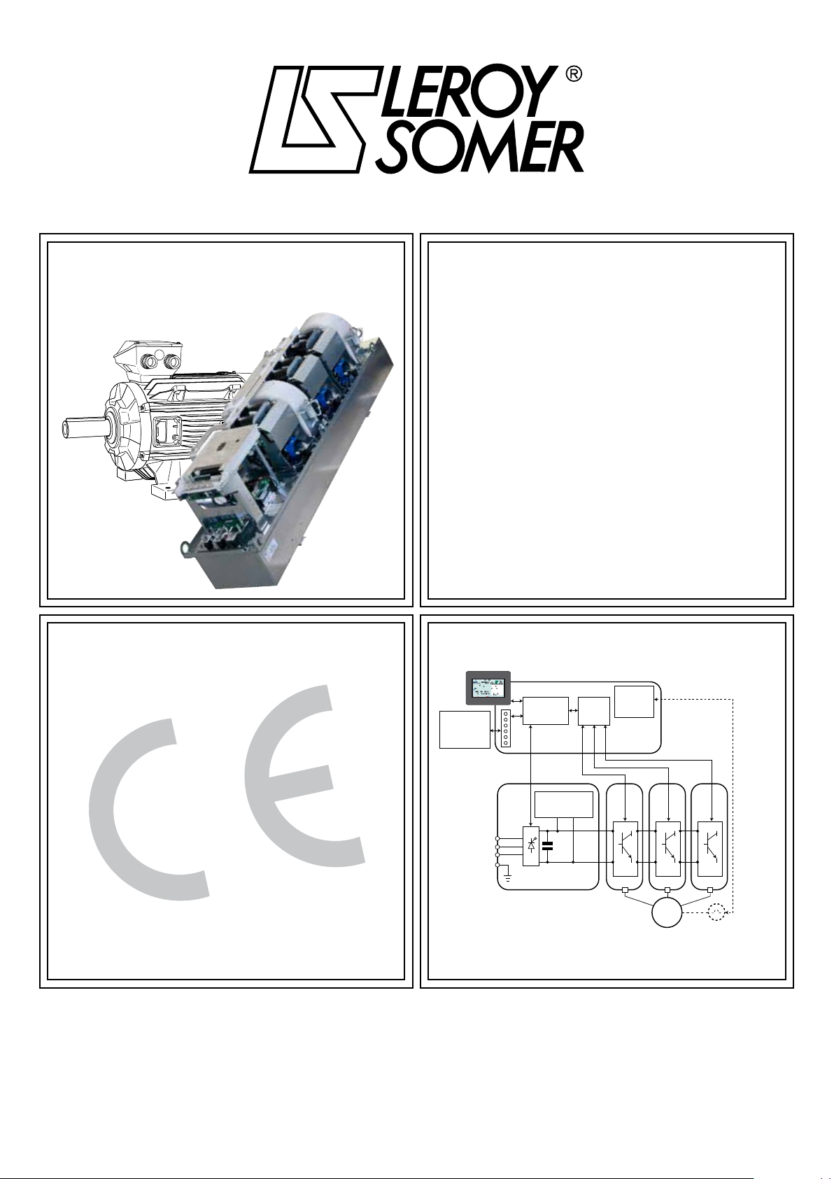
POWERDRIVE MD2CS
3
en
INSTALLATION AND MAINTENANCE
Chassis-mounted variable speed drive
SAFETY AND OPERATING INSTRUCTIONS FOR VARIABLE SPEED DRIVES
(In accordance with the low voltage directive 2006/95/EC)
Throughout the manual, this symbol warns of
consequences which may arise from inappropriate
use of the drive, since electrical risks may lead to material
or physical damage as well as constituting a re hazard.
1 - General
Depending on their degree of protection, the variable speed
drives may contain unprotected live parts, which may be moving
or rotating, as well as hot surfaces, during operation.
Unjustied removal of protection devices, incorrect use, faulty
installation or inappropriate operation could represent a serious
risk to personnel and equipment.
For further information, consult the documentation.
All work relating to transportation, installation, commissioning
and maintenance must be performed by experienced, qualied
personnel (see IEC 364, CENELEC HD 384 or DIN VDE 0100,
as well as national specications for installation and accident
prevention).
In these basic safety instructions, qualied personnel means
persons competent to install, mount, commission and operate
the product and possessing the relevant qualications.
2 - Use
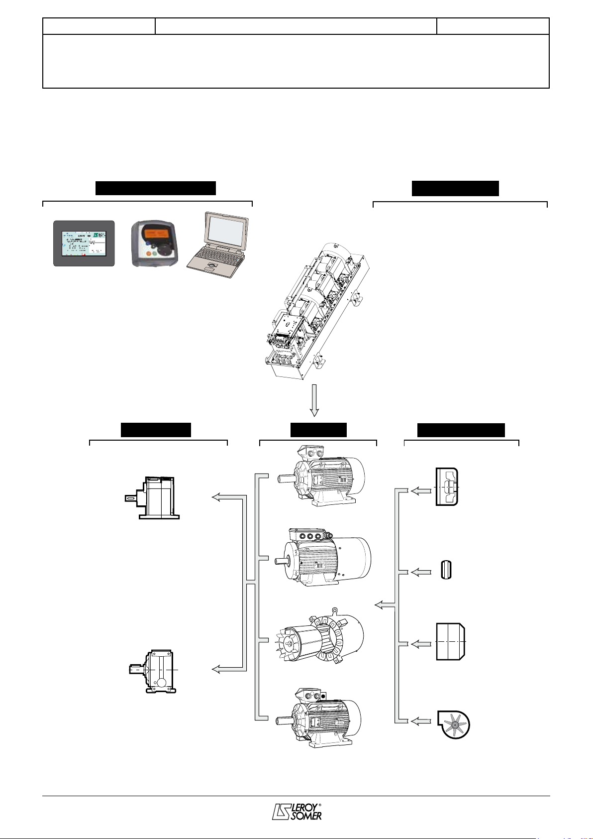
Variable speed drives are components designed for integration
in installations or electrical machines.
When integrated in a machine, commissioning must not take
place until it has been veried that the machine conforms with
directive 2006/42/EC (Machinery Directive). It is also necessary
to comply with standard EN 60204, which stipulates in particular
that electrical actuators (which include variable speed drives)
cannot be considered as circuit-breaking devices and certainly
not as isolating switches.
Commissioning can take place only if the requirements of the
Electromagnetic Compatibility Directive (EMC 2004/108/EC)
are met.
The variable speed drives meet the requirements of the Low
Voltage Directive 2006/95/EC. The harmonised standards
of the DIN VDE 0160 series in connection with standard VDE
0660, part 500 and EN 60146/VDE 0558 are also applicable.
The technical characteristics and instructions concerning the
connection conditions specied on the nameplate and in the
documentation provided must be observed without fail.
3 - Transportation, storage
All instructions concerning transportation, storage and correct
handling must be observed.
The climatic conditions specied in the technical manual must
be observed.
4 - Installation
The installation and cooling of equipment must comply with the
specications in the documentation supplied with the product.
The variable speed drives must be protected against any
excessive stress. In particular, there must be no damage to
parts and/or modication of the clearance between components
during transportation and handling. Avoid touching the electronic
components and contact parts.
The variable speed drives contain parts which are sensitive to
electrostatic stresses and may be easily damaged if handled
incorrectly. Electrical components must not be exposed to
mechanical damage or destruction (risks to health!).
5 - Electrical connection
When work is performed on variable speed drives which are
powered up, the national accident prevention regulations
must be respected.
The electrical installation must comply with the relevant
specications (for example conductor cross-sections,
protection via fused circuit-breaker, connection of protective
conductor). More detailed information is given in the
documentation.
Instructions for an installation which meets the requirements
for electromagnetic compatibility, such as screening, earthing,
presence of lters and correct insertion of cables and
conductors, are given in the documentation supplied with the
variable speed drives. These instructions must be followed
in all cases, even if the variable speed drive carries the CE
mark. Adherence to the limits given in the EMC legislation is
the responsibility of the manufacturer of the installation or the
machine.
6 - Operation
Installations in which variable speed drives are to be
integrated must be tted with additional protection and
monitoring devices as laid down in the current relevant safety
regulations, such as the law on technical equipment, accident
prevention regulations, etc. Modications to the variable
speed drives using control software are permitted.
Active parts of the device and the live power connections
must not be touched immediately after the variable speed
drive is powered down, as the capacitors may still be charged.
In view of this, the warnings xed to the variable speed drives
must be observed.
Permanent magnet motors generate electrical energy while
they are rotating, even when the drive is switched off. In
this case, the drive continues to be powered by the motor
terminals. If the load is capable of turning the motor, a
switching device must be provided upstream of the motor to
isolate the drive during maintenance operations.
During operation, all doors and protective covers must be
kept closed.
7 - Servicing and maintenance
Refer to the manufacturer’s documentation.
See the Maintenance section in this document.
This manual is to be given to the end user.