bluMartin freeAir 100 User manual

www.bluMartin.de
Operating Manual
[ G ] General
[ O ] Operation
[ I ] Installation
[ S ] Service

Kurzanleitung
Quick Start Guide
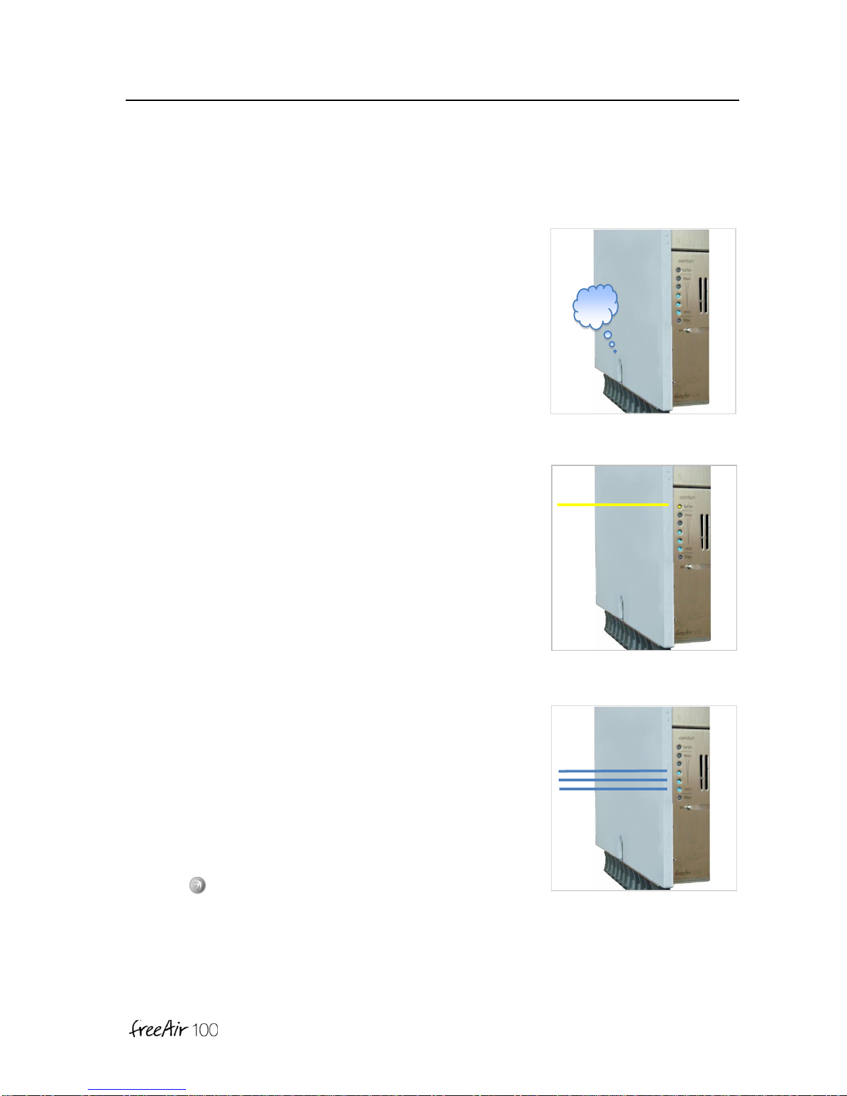
Switching On / Off
Press the on switch.
Start-up routine and self check can take a few minutes –turning it
off can take a few seconds. All LEDs will blink (all colors).
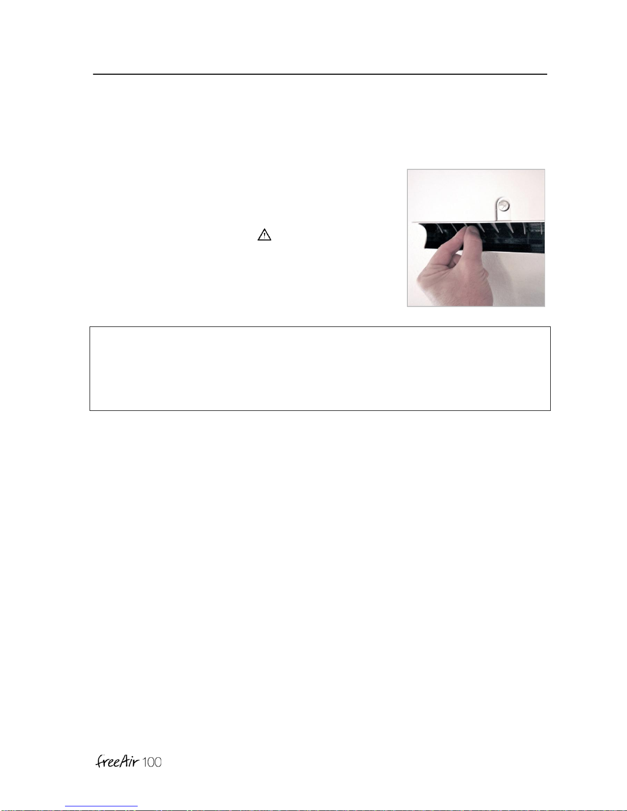
Comfort Level
Press the - Button repeatedly to change the Comfort Level.
More blue LEDs mean a more active operation (minimum
ventilation, humidity, CO2, cooling ... etc.). However, a change in
Comfort Level does not have to lead to the immediate increase in
fan speed.
Blinking or flashing blue LEDs indicate Service or Dehumidification
Operation.
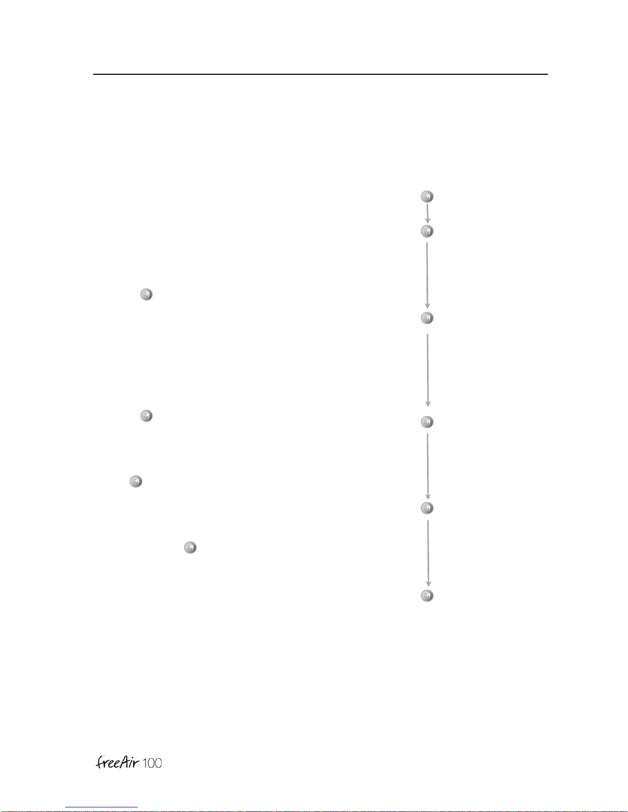
Turbo / Sleep / Turbo Cool
Push the - Button until you hear 4 short beeps. This should be
selected if you wish to air out rooms at the highest device setting for
30 minutes. Push and hold the - Button longer and your
freeAir100 will pause for 90 minutes.
To start Turbo Cool Function for a maximum duration of 3 hours
push and hold the button yet longer for.
Beep
→Comfort Level
Beep
Beep
Beep
Beep
→Turbo
B
e
e
e
p
→Sleep
Beep
Beep
Beep
Beep
→Turbo Cool

General
1
[ G ]
Dear customer
We thank you for choosing the freeAir ventilation system. Please thoroughly read and follow this
manual.
After successful installation please select the desired Comfort Level to activate the device.
Proper operation is now taken care of by the sensors and the intelligent controller of your
freeAir.
Enjoy the ambiance offered by the right amount of fresh air.
Your bluMartin-Team

General
2
[ G ]
General
Safety –General
This manual is only valid for the fresh air system freeAir100.
This manual is delivered as part of the device. Please keep this manual readily available.
Please make sure all persons operating the device are familiar with this manual. Please
observe all instructions given in this manual.
Installation, commissioning and servicing must only be performed by sufficiently qualified
persons.
Neglect to adhere to this manual will void the warranty.
Please also observe our general terms and conditions. Please see www.bluMartin.de/cos .
Safety –Icon
DANGER
This sign indicates danger by potentially deadly electrical shock.
DANGER
This sign indicates that instructions must be followed precisely in order to prevent personal or
material damage.
Warning
To avoid any property damage please pay special attention to this sign.
General
3
[ G ]
Notes
This sign emphasizes important information.
Safety indications
DANGER
•The device uses electrical power. Some parts of the device carry line voltage even several
minutes after unplugging the device.
•Never open the device while appliance is plugged in.
•Electrical installation as well as electrical service work must only be performed by qualified
personnel.
•Electrical installation has to be in accordance with the appropriate national association
or electrical code.
•The device may only be operated in good condition and unaltered condition.
•All instructions and notes with respect to maintenance (see Service paragraph) are to be
implicitly followed.
•Only operate if device is in good technical order.
In case of error or damages that constitute a safety issues turn the device off.
Prevent the device from being turned back on by unauthorized persons, and have the
device immediately repaired by a qualified technician.
•Use original bluMartin GmbH repair and service parts only.
General
4
[ G ]
Intended use
The freeAir100 is a decentralized fresh air ventilation system with heat recovery. The purpose of
the device is to ventilate one or more rooms in apartments or houses. The device is installed in
an outside wall.
Expended air is drawn from the room the device is installed in. The air is drawn from other
rooms (such as kitchen or bathroom) in case the 2nd room extract option is installed.
Fresh and filtered air is returned to the room the device is installed in. The addition of the 2nd
room supply option enables fresh and filtered air return to an additional room for instance a bed
room.
Inappropriate use
The device is exclusively to be used for ventilation purposes.
DANGER
Only air not containing flammable, explosive or corrosive components or air not containing any
other dangerous or hazardous components must be used for ventilating purposes.
Disposal
Dispose of the freeAir100 in accordance with your local rules, regulations or guide lines.
Please pay special attention to correctly sorted metal, plastics and electronics.
General
5
[ G ]
Transport and Storage
Components of the freeAir100 may only be transported in the intended packaging. To protect
the device from mechanical shock the freeAir100 has to be shipped in its original packaging and
strapped to a pallet. Packaging must be protected from moisture.
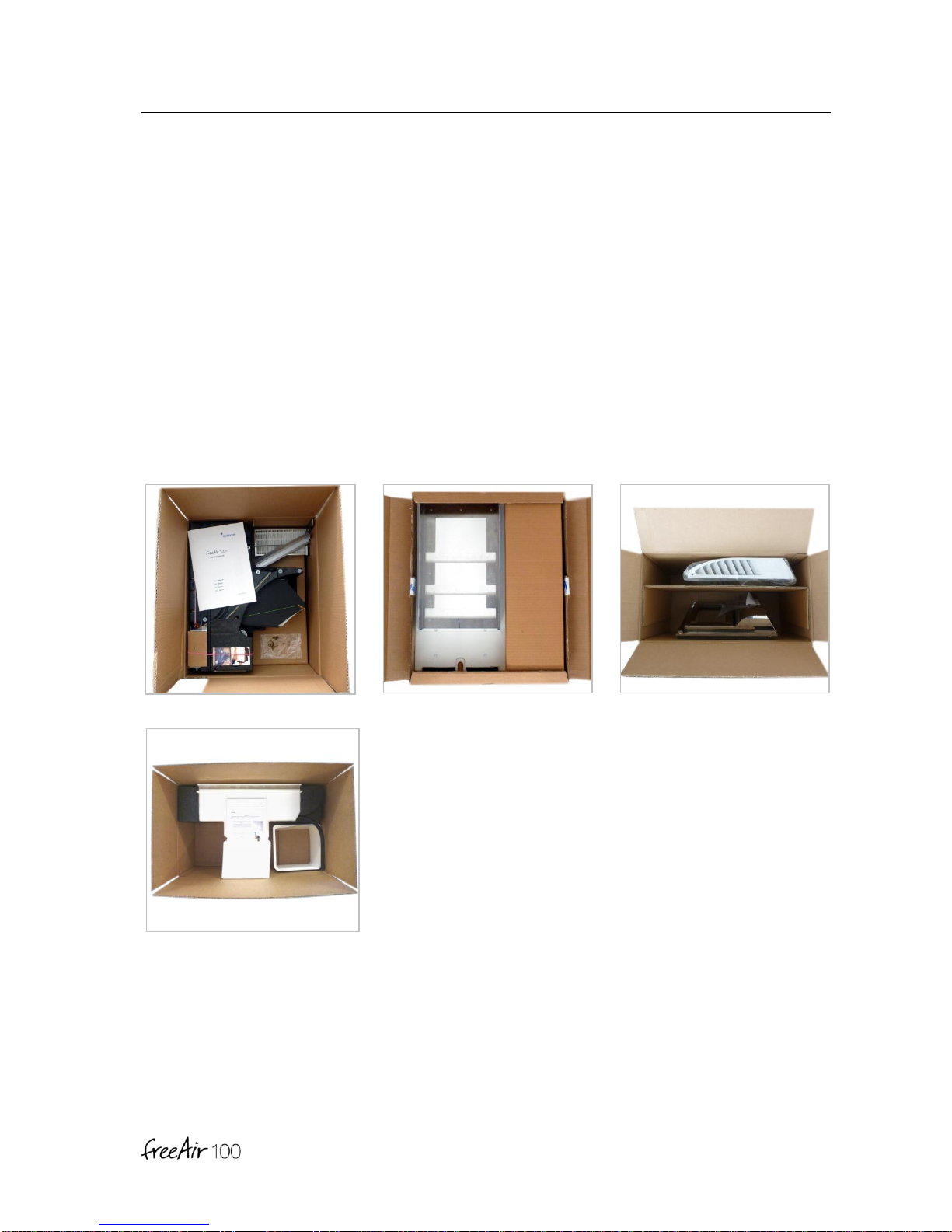
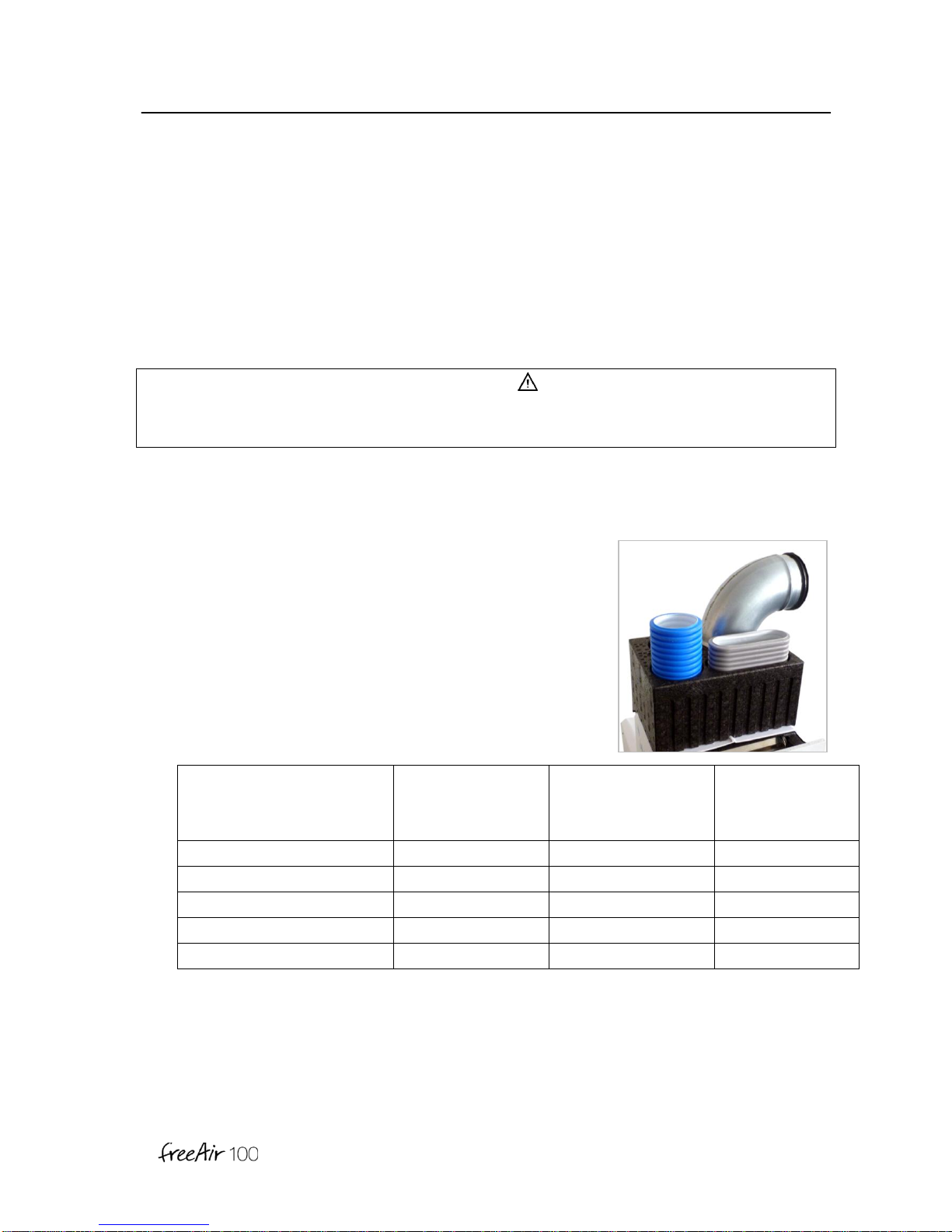
Included in Shipping
freeAir 100 Front plate Outside hood
Bare brickwork set

General
6
[ G ]
Technical Data
Dimensions inside front 28 x 58 cm
Wall thickness 32 to 53 cm incl. stuck
(under 40 cm => deeper hood; over 53 cm => extension)
Air stream 20 to 100 m3/h
Heat supply gradient 87 % (by PHI criteria and EN 13141-8)
Heat recovery 94 % (at 50 % relative humidity)
Heat exchanger type Counter current flow; Aluminum
Line voltage 95 to 265 V AC
Line fuse 3 A quick (on motherboard)
Line frequency 45 to 65 Hz
Energy usage Standby → 1 W; 20 m3/h →4 W;
50 m3/h →13 W; 100 m3/h → 40 W (max. tube length + F7)
Weight 10 kg
Noise level in room 20 m3/h →17 dB (A) (distance of 1 m);
30 m3/h →22 dB (A);
50 m3/h →34 dB (A); 100 m3/h → 51 dB (A)
Noise dampening Standby → 52 dB;
Operation → 46 dB (DIN EN 20140-10; Dn, e, w)
Control Intelligent 5-step Comfort Control
Air stream control Automatic; 8 speeds; volume constant; balanced ventilation
CO2control Automatic
Dehumidification Automatic and special operation
Summer cooling Automatic and with Turbo Cool
Anti freeze protection Automatic bypass-control at about -5°C outside
Temperature range -40 to +50°C outside and 0 to +40°C inside
Filter –supply air Fine particle filter M5 (pollen protection) or F7 (allergy)
Filter –exhaust air Fine particle filter M5 (EN 779)
Color Front plate primer (ready to paint or arrange)
DIBt license Z-51.3-287
Operation
7
[ O ]
Operation
DANGER
Respect all references regarding safety and use of the freeAir100 in part General [G]!
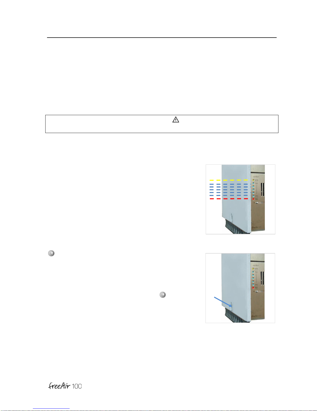
Display- and Operating Elements
on Main Switch
Use for turning the freeAir on or off.
All LEDs will blink slow during start and self-test operation.
Firmware version is indicated by individual non-illuminating
LEDs (digitally starting from the bottom).
During a controlled „Shut Down“ LEDs will blink fast. Vent flaps
are being shut.
- Button
Operation of your freeAir100 is so simple –you only need this
button as the only control element.
With this button you can control Comfort Level, start or stop the
Turbo, select Sleep or Dehumidification mode (see below).
You can change the Comfort Level by pushing - Button
several times fast. The more blue LEDs are lit the more active
the instrument controls (minimum ventilation, CO2, humidity,
cooling...).
Changing Comfort Level may not immediately change fan speed.
Operation
8
[ O ]
Audible Signals
A continuous beep-sound indicates occurrence of excessive
temperatures or harmful CO2-Concentrations.
(See part [S] Service).
Yellow LED
This LED will blink slowly during Turbo operation.
Continuous illumination indicates:
reduced minimum ventilation due to active defrost function
eliminating room air humidification, or
the freeAir pauses,
- because outside air is so humid that room air condensation
could occur,
- because outside temperatures are below -22°C (-30°F).
this LED will blink fast during Turbo Cool operation.
Blue LEDs
The number of illuminated blue LEDs indicates the selected
Comfort Level.
These LEDs will blink slowly during Sleep mode.
These LEDs will flash during Dehumidification mode.
Note
Blue LEDs will go dark after 3 minutes so as not to disturb you.
Push the - Button to “wake” them up.
Piep

Operation
9
[ O ]
Red LED
A fast blinking red LED indicates that the last filter change has
been more than 8,000 hours ago (~ 1 year).
A slow blinking red LED indicates that the air stream through a
dirty and partially clogged filter is impaired. A slow blinking red
LED can also indicate air stream obstructions such as
inappropriately dimensioned openings between spaces of
supply and extract air.
Continuous illumination indicates control error. (See appendix
[S] Service).
DANGER
•An overly dirty filter (indicated by the red LED) can reduce supply and extract air flow. This
in turn can lead to diminished air quality and over or under pressure in connected rooms.
•Diminished oxygen levels can pose a health risk.
•A dirty filter can also grow germs.
USB Port
The USB port on the left side of the device serves as
a connection to the (free to our customers) freeAir-
Connect software and respective updates.
Note
Please visit our website at www.bluMartin.de for
updates under Service / Downloads.
Operation
10
[ O ]
Louver
The louver in the left part of the air output side can be rotated to
accommodate any desired blow direction.
DANGER
Do not insert any foreign objects into the supply opening.
Notes
•Due to the optional 2nd room air supply connection - air is only supplied from the left part of
the air discharge.
•In case the included supply air outlet for wide through results in drafty condition alternative
supply air outlet hardware is available.
Operation
11
[ O ]
Comfort Operation
After switching it on the freeAir100 will operate in Comfort mode. In
this mode the device will operate automatically:
If installed correctly the device will supply all connected living areas
with the right amount of fresh air. Minimum air flow, CO2 content,
relative and absolute humidity inside and out are all taken into
account.
Push the - Button several times to select Comfort Level 1 (one
LED). This is the quietest level and should be selected if you like a
quiet setting for instance for bed rooms.
Level 3 (3 LEDs are lit) is the normal setting for living rooms.
Turbo Operation
Push the - Button until you hear 4 short beeps. This model
should be selected if you wish to air out rooms at the highest
device setting for 30 minutes. Comfort operation will be restored
automatically after 30 minutes. Comfort Level can also be restored
via the - Button.
Sleep Mode
Push and hold the - Button until you hear 4 short beeps followed
by a very long beep. Your freeAir100 will pause for 90 minutes
before switching back to Comfort mode.
Beep
→Comfort Level
Beep
Beep
Beep
Beep
→Turbo
B
e
e
e
p
→Sleep
Beep
Beep
Beep
Beep
→Turbo Cool
15 seconds
Beep
Beep
Beep
→Dehumidification
Operation
12
[ O ]
Turbo Cool Operation
Start Turbo Cool operation by pushing and holding the - Button till you hear 4 short beeps
followed by a long beeps followed again by 4 short beeps. This will open the bypass flap and
switch the device to its highest power setting for 3 hours. In this setting your living space can be
cooled down noticeably by fresh evening and night air after a hot day.
Turbo Cool operation is switched off automatically when outside air temperature is too hot.
Dehumidification Operation
Push and hold the - Button for 15 seconds to activate this mode. This operation can be used
in case of an application where the usual dehumidification level provided by the Comfort mode
is not sufficient (for instance in a basement room). The freeAir100 will beep three times and
blue LEDs will flash. Dehumidification will work at humidity levels as low as 45 % relative
humidity. Dehumidification is optimally controlled through constant measuring of absolute
humidity both inside and outside effectively suppressing humidity import through outside air.
Installation
13
[ I ]
Installation
DANGER
Please see part General [G] for safety notes. Observe all notes with respect to safety and use of
the freeAir100.
2nd Room Connections
1. Please select the correct connector for a device designed
for 2nd room connection:
•Connecting ducting, conduits and valves must have
low air stream resistance.
•For 2nd room connection the below stated decrease
in pressure must not be exceeded.
•The supply air conduits must not exceed
the below noted length.
Type of Conduit
Max. Air Flow for
2nd Room Exhaust
(= DIP switch setting)
Max. Pressure drop
2nd Room Exhaust
(at max. air flow)
=> Max. Length
(pressure drop for turns and
valves included)
1 x Flat-Flex 51 x 138 mm
30 m3/h
15 Pa
ca. 8 m
1 x Round-Flex 75 mm
30 m3/h
15 Pa
ca. 2.5 m
2 x Round-Flex 75 mm
60 m3/h
55 Pa
ca. 10 m
3 x Round-Flex 75 mm
100 m3/h
65 Pa
ca. 10 m
1 x Round 100 mm
100 m3/h
65 Pa
ca. 12 m

Installation
14
[ I ]
Notes
•The freeAir compensates for air stream resistance, due to connected conduit or dirty filter,
by increasing fan speed.
•Therefore supply and exhaust air stream remain constant and balanced.
•“Dirty Filter” error will be indicated once maximum fan speed is reached.
•Longer supply ducting will result in a change in balance between the air flow of the 1st and
2nd room in favor of the 1st room (normal 1 : 1).
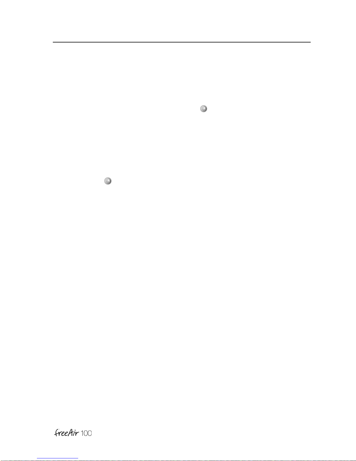
2. Cut out the appropriate passage and attach the
appropriate ducting or connector taking care to use an O-
ring or sealant.
3. Use the included adapter if you wish to connect the 3x
Round-Flex 75 mm to the 2nd Room Exhaust port.
Installation
15
[ I ]
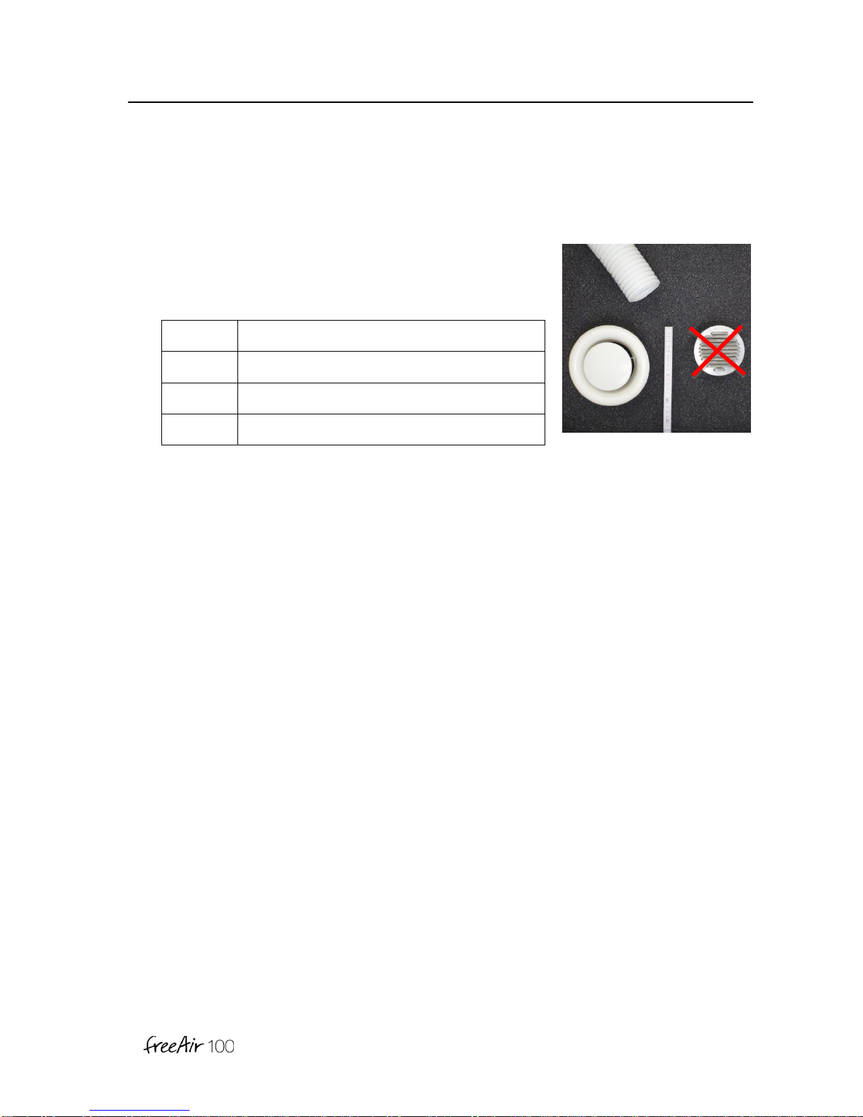
4. Allow for sufficient openings between rooms (clearance
between door frame and door leaf) and sufficiently sized
supply and exhaust valves:
Air Flow
Minimal Cross Section Area
30 m3/h
30 cm2(Valve Ø 125 mm)
60 m3/h
60 cm2 (Valve Ø 125 mm, fully opened)
100 m3/h
100 cm2(Valve Ø 200 mm)

Installation
16
[ I ]
Installation Side
DANGER
•The freeAir100 must not be installed in immediate vicinity of flammable material or
harmful chemicals.
•During planing consider all relevant local building, safety and fire codes. Especially in
situations where indoor air is used for combustion (wood stove, fire place...etc.).
Select installation location that allows condensing moisture to
flow off freely while preventing any danger through the formation
of icicles and/or icy spots on the ground.
Notes
•The condensate may be drained through a hose with the extra Condensate drain outside
article FA00.2005 (outside between wall and insulation or inside).
•The formation of ice can be reduced with the software option de-icing (only with the
permission of the owner of the building).
Installation
17
[ I ]
Warning
The freeAir100 is not 100% suitable for tropical locations with high humidity. In such locations
condensate could result on the inside part of the device (the freeAir will pause in these cases).
The system has jet no design features allowing drainage from the inside.
Room temperature during operation should be between 0°C and 40°C. Outside temperature
should be between -40°C and +50°C.

Installation
18
[ I ]
Drawings
Table of contents
Popular Ventilation Hood manuals by other brands


 Operating instruction")


STOVES
STOVES S1100 User & installation instructions

Novy
Novy Phantom Cable Operating and installation instructions

Miele
Miele VENTILATION SYSTEM DA 6290 W Operating and installation instructions

GE
GE JV960SCBR Specification sheet

Uberhaus
Uberhaus 22275000 Operator's manual

Smeg
Smeg K28X Installation and operating instructions