EN 1
11
RECOMMENDATIONS AND SUGGESTIONS
The Instructions for Use apply to several versions of this appliance. Accord-
ingly, you may find descriptions of individual features that do not apply to
your specific appliance.
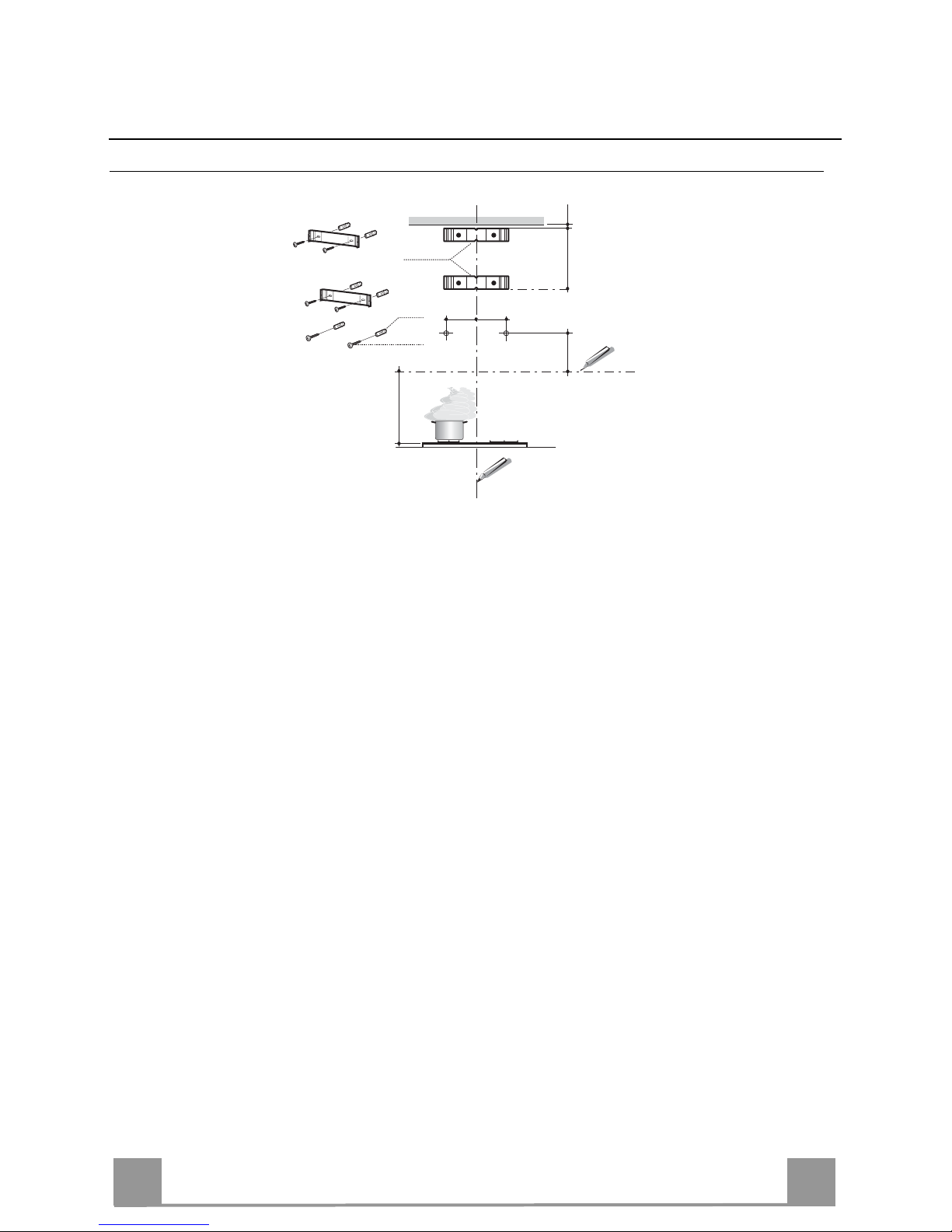
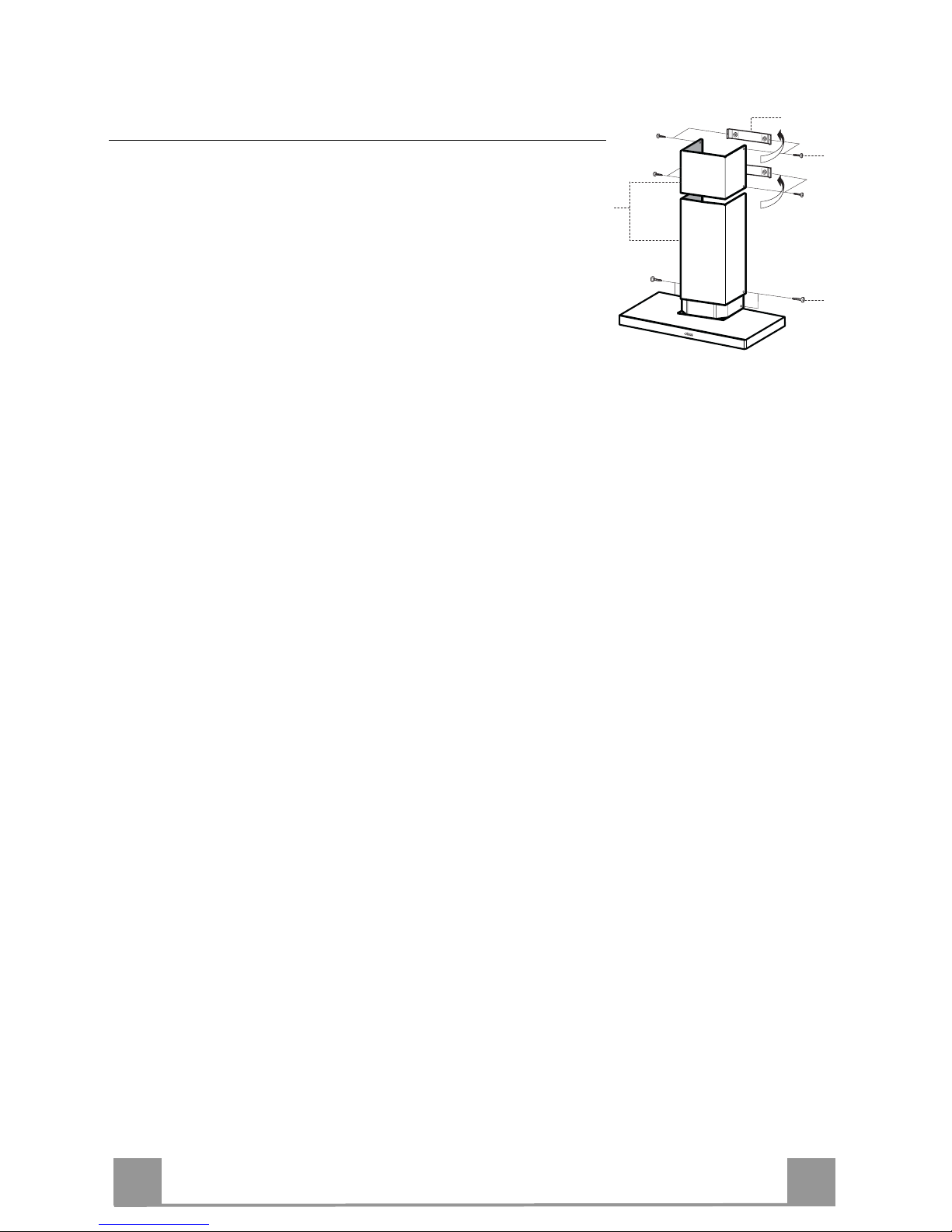
INSTALLATION
• The manufacturer will not be held liable for any damages resulting from in-
correct or improper installation.
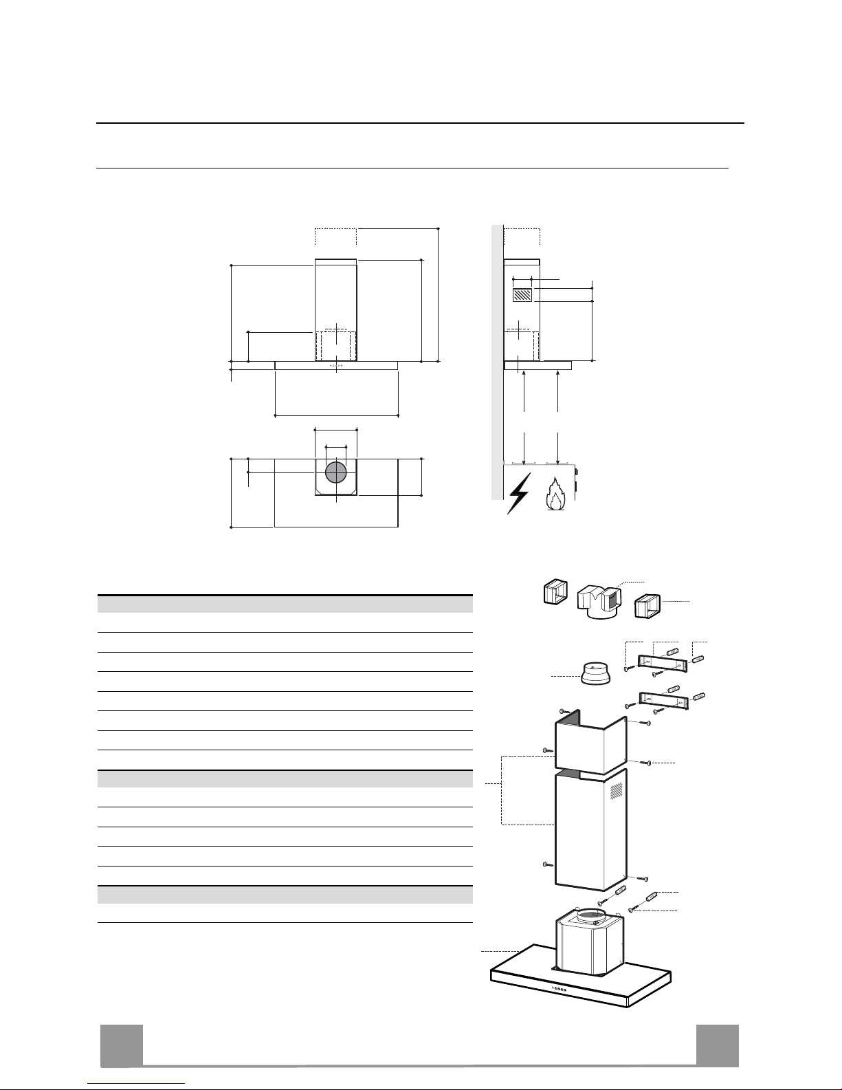
• The minimum safety distance between the cooker top and the extractor
hood is 650 mm (some models can be installed at a lower height, please re-
fer to the paragraphs on working dimensions and installation).
• Check that the mains voltage corresponds to that indicated on the rating
plate fixed to the inside of the hood.
• For Class I appliances, check that the domestic power supply guarantees
adequate earthing.
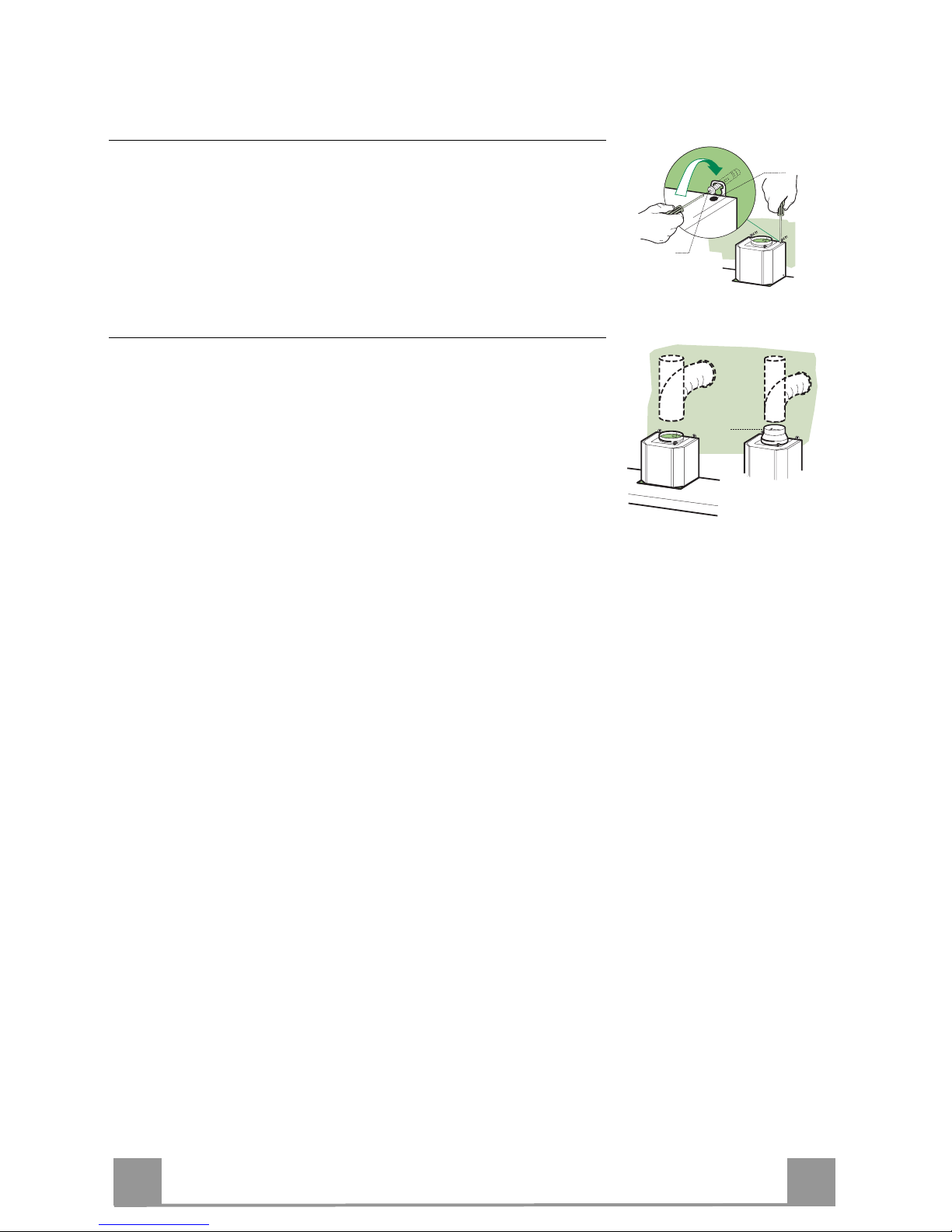
Connect the extractor to the exhaust flue through a pipe of minimum diame-
ter 120 mm. The route of the flue must be as short as possible.
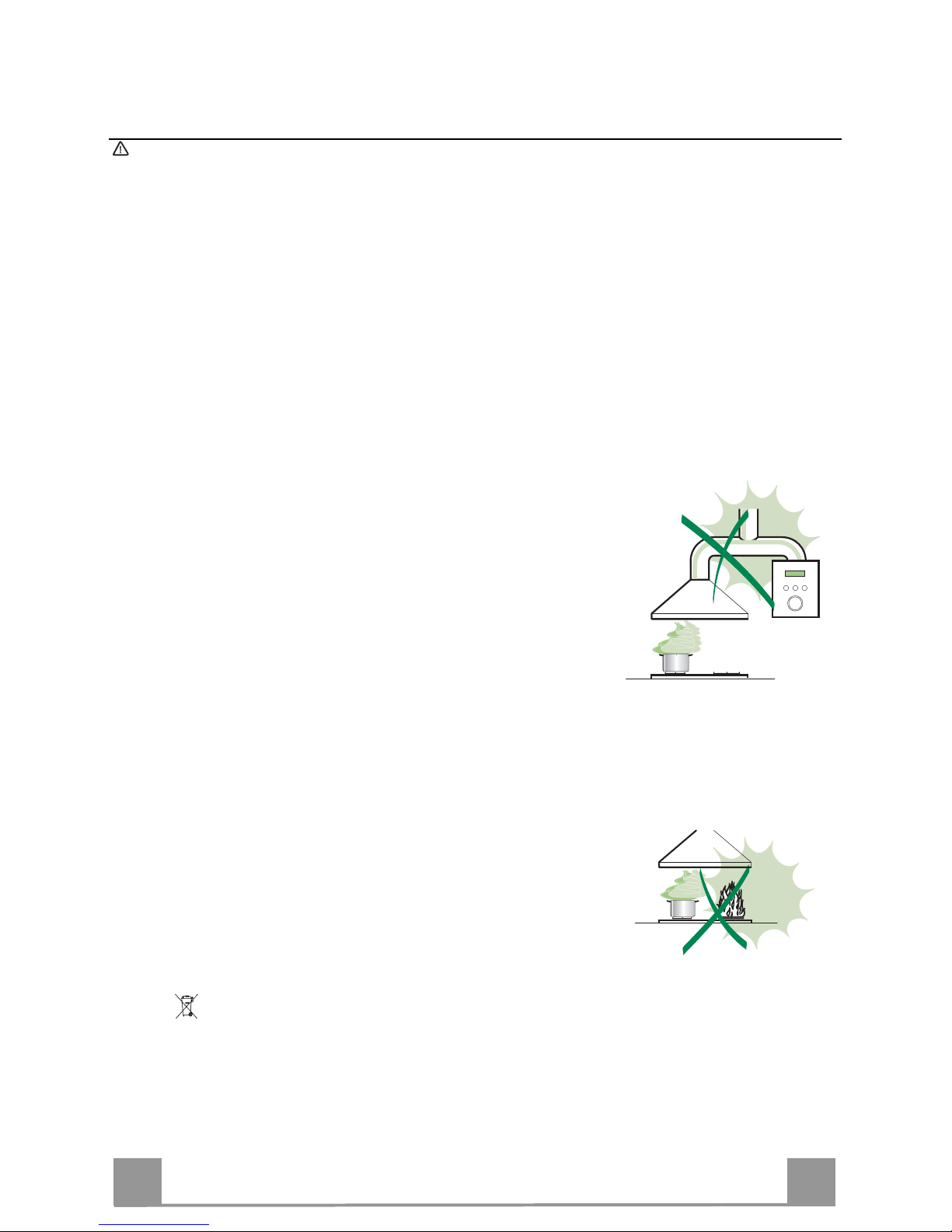
• Do not connect the extractor hood to exhaust ducts carrying combustion
fumes (boilers, fireplaces, etc.).
• If the extractor is used in conjunction with non-electrical appliances (e.g. gas
burning appliances), a sufficient degree of aeration must be guaranteed in
the room in order to prevent the backflow of exhaust gas. The kitchen must
have an opening communicating directly with the open air in order to
guarantee the entry of clean air.
USE
• The extractor hood has been designed exclusively for domestic use to elimi-
nate kitchen smells.
• Never use the hood for purposes other than for which it has been designed.
• Never leave high naked flames under the hood when it is in operation.
• Adjust the flame intensity to direct it onto the bottom of the pan only, making
sure that it does not engulf the sides.
• Deep fat fryers must be continuously monitored during use: overheated oil
can burst into flames.
• Do not flambè under the range hood; risk of fire
• This appliance is not intended for use by persons (including children) with
reduced physical, sensory or mental capabilities, or lack of experience and
knowledge, unless they have been given supervision or instruction concern-
ing use of the appliance by a person responsible for their safety.
• Children should be supervised to ensure that they do not play with the appli-
ance.
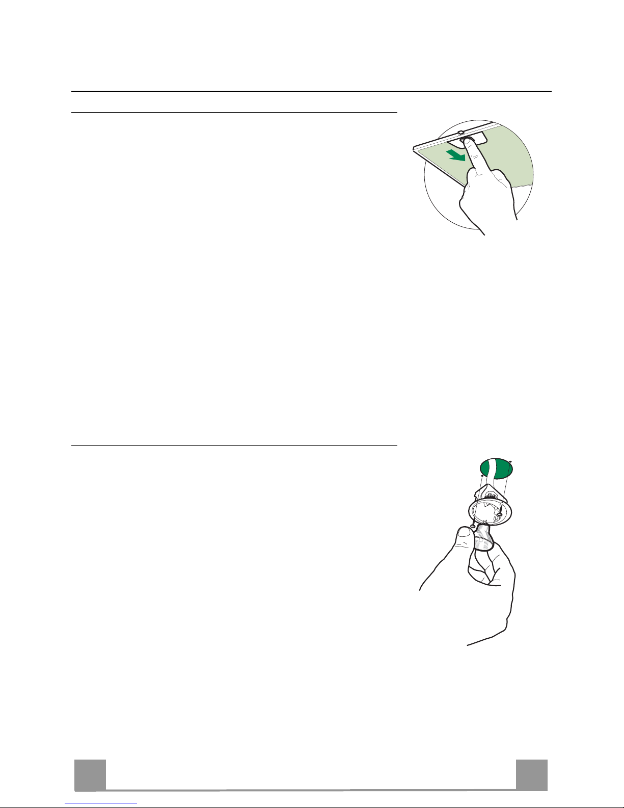
MAINTENANCE
• Switch off or unplug the appliance from the mains supply before carrying out
any maintenance work.
• Clean and/or replace the Filters after the specified time period (Fire hazard).
• Clean the hood using a damp cloth and a neutral liquid detergent.
The symbol on the product or on its packaging indicates that this product may not be treated
as household waste. Instead it shall be handed over to the applicable collection point for the
recycling of electrical and electronic equipment. By ensuring this product is disposed of correctly,
you will help prevent potential negative consequences for the environment and human health,
which could otherwise be caused by inappropriate waste handling of this product. For more
detailed information about recycling of this product, please contact your local city office, your
household waste disposal service or the shop where you purchased the product.