BM KAPTOR MINI User manual

KAPTOR MINI
User Manual
Firmware Revision: Flow-V1.3.4 / Standard-V1.0.0
App Revision: Easysetup 1.5.1
Manual Revision: V0.1 dtd 30/03/2020


KAPTOR MINI –User Manual –V0.1 - pg.2
Documents revision
REV.
Type of Revision
Approval
Date
01
First Version in English
30/03/2020

KAPTOR MINI –User Manual –V0.1 - pg.3
1Summary
1 Summary 3
2 Introduction 6
2.1 Manual feasability 7
3 General information 8
3.1 Main sensors 9
3.2 Main applications 9
3.3 Technical, functional, electrical and mechanical features 10
3.4 Functional features 11
4 Dimensions and fixing system 14
4.1 Mouting bracket 15
4.2 Quick release wall mounting support 15
4.3 Combined mounting bracket 16
5 Case opening and closure 17
6 Power supply 19
6.1 Primary internal battery (not rechargeable) –3,6V 19
6.1.1 Internal battery replacement 19
6.2 Exernal rechargeable battery 20
6.2.1 Battery charging 21
6.3 External primary battery (not rechargeable) –14,4V 22
6.4 External power supply 22
6.5 Battery selector 22
7 Wiring and connections 24
7.1 Wiring ID colours 25
8 SIM card 27
9 Working modes 29
9.1 Continuous mode 29
9.2 Discontinuous/Low power Mode 29
9.3 Data transmission 30
9.4 Freezing 30
10 Status led 31
11 App EasySetup 32

KAPTOR MINI –User Manual –V0.1 - pg.4
11.1 Device features for App EasySetup Installation 32
11.2 Installation and update 33
11.3 Authorizations 33
11.4 How does EasySetup works? 34
11.4.1 App working mode (live and off-line) 34
11.4.2 Status bar 35
11.4.3 App Settings 36
11.4.4 Codes and Passwords 37
11.5 Wi-Fi Connection to the device 37
11.6 Profiles management 38
11.6.1 Duplication and association of profiles 39
11.7 “Save” and “Save and upload” buttons 40
12 Configuration 41
12.1 Sensors connected to RS485 port 41
12.1.1 RS485 standard 41
12.1.2 RS485 flow 44
12.2 Built-in pressure sensor 54
12.3 Analog inputs 54
12.4 Digital inputs 55
12.5 Auto cleaning 56
12.6 Warm up time 57
12.7 Variables log 57
12.8 Data 58
12.8.1 Real time data 58
12.8.2 Historical Data 58
12.9 Communication 60
12.9.1 Connection parameters 61
12.9.2 Data Transmission 62
12.9.3 SIM 64
12.9.4 Functional test 65
12.10 Alarms and events 66
12.10.1 Thresholds 66

KAPTOR MINI –User Manual –V0.1 - pg.5
12.10.2 Users 67
12.10.3 Digital events 67
12.10.4 Download events 68
12.10.5 Reset alarms 68
12.10.6 Diagnostics 68
12.11 Service Function 69
12.11.1 Reboot 69
12.11.2 Firmware Update 69
12.11.3 Wi-Fi password 69
12.11.4 Set modem profile 70
12.11.5 Battery calibration 70
12.11.6 Factory settings 71
13 Conformity standards 72
14 Conformity certificates of manufacturer 73
15 Maintenance 75
16 Service 75
17 Warranty 75
18 Disposal 75
19 Ordering Code 76
KAPTOR MINI –User Manual –V0.1 - pg.6
2Introduction
Please read this part carefully before starting using the device.
Dear Customer,
congratulations for choosing a product manufactured by B.M. Tecnologie Industriali.
This manual is the main source of information for the right use of KAPTOR MINI.
This manual includes important information, advices and warnings for the right use of the device and its
potentials.
Please read this manual carefully and before starting any installation procedure. Pay attention to the
notes referring to Warnings and Safety.
Keep the manual in a safe place and ready to use in any moment.
If you have problems or cannot understand the information included, please contact the manufacturer or
its local Distributors.
The manufacturer, B.M. Tecnologie Industriali srl, is not responsible for any damages to
people or things caused by the misuse of the device.
The manual states the right way to use it.
This manual describes all the functions of KAPTOR MINI, referring to any specific version of
hardware and/or software. Optional contents, dedicated functions or peculiar versions are
NOT tagged specifically. You just need to consider only the information referring to the device
you have. Contents implemented during the device working period are precisely identified.
B.M. Tecnologie Industriali is constantly improving its devices, though it has the right to
change the device’s features for commercial/technical purposes. For further information,
please contact the sales team of B.M. Tecnologie Industriali.

KAPTOR MINI –User Manual –V0.1 - pg.7
2.1 Manual feasability
This manual describes features, functions, and instructions for using KAPTOR MINI. For installation and
start-up of the sensors, please refer to their specific manuals.

KAPTOR MINI –User Manual –V0.1 - pg.8
3General information
KAPTOR MINI is the evolution of KAPTOR MULTI, successfully used in thousands of applications.
This device was developped and realized by B.M. Tecnologie Industriali as a central element of a system
managing measures, data acquisitions and transmissions. Its unique features make it a milestone in the
whole panorama of similar devices.
It has its main use in all the fuctions regarding water cycle, such as: flow rate and pressure measurement
in full pipes or open channels, parameters analysis on drinking and waste water, spillways and overflows
activations, submerged and not contact level measurement, events acquisition (on/off), etc. etc.
KAPTOR MINI can be supplied by an internal primary or rechargeable battery to manage itself the sensors
connected to analog and digital inputs, but it could also be supplied by an external battery, connected to
a dedicated input, to manage sensors with higher power consumption.
External high capacity battery can be easily removed and replaced.
KAPTOR MINI is suitable for medium and long term monitoring campaigns. Its built-in memory can record
over 800.000 records.
Its built-in modem allows transmission of saved data and diagnostics to a remote server in order to
monitor the device’s status and the data reading. The device could be equipped with a built-in high
efficiency antenna for data transmission even if the signal is low, or with an external antenna.
KAPTOR MINI can manage alerts on every variable through the event recording, transmitting to a remote
server, sending SMS to a list of users.
IP68 protection of the datalogger unit and its modules complete the excellent performances of this device.
EasySetup App for AndroidTM, connecting via Wi-Fi, thanks to its simple interface, similar to smartphones,
allows the user to setup the device and read data.

KAPTOR MINI –User Manual –V0.1 - pg.9
3.1 Main sensors
✓Area velocity doppler sensor for flow measurement on part filled pipes and open channels.
✓Transit Time module for flow measurement on full pipes.
✓Pressure sensor for pressure measurement of full pipes.
✓Ultrasonic sensor for level/flow measurement on open channels.
✓Overflow sensor for overflow detection.
✓Analytical sensors for the analysis of water quality and chemical-physical parameters.
✓Digital pulse inputs for volumetric flow meters reading.
✓Digital event inputs for monitoring on/off status (activation)
✓Connection of standard 4..20mA or 0..10V sensors for standard signal recording.
3.2 Main applications
✓Water Losses: DMAs and measurement of inflows.
✓Monitoring Campaigns for the calibration of mathematical models.
✓Measurement in the sewage networks for overflow activation and volumes.
✓Water losses in water networks.
✓Search for extraneous waters in sewage networks.
✓DMAs –District Metered Areas.
✓Overflow check.
✓Fire systems check.
✓Calibration of numerical models.
✓Long and short term measurement campaigns in aqueducts and sewers.
✓Water balances.
✓Pumping stations.
✓Water treatment plants.
✓Hydroelectric plants.
✓Industrial processes monitoring.

KAPTOR MINI –User Manual –V0.1 - pg.10
3.3 Technical, functional, electrical and mechanical features
HARDWARE FEATURES DATALOGGER KAPTORMINI
I/O
2 Analog Inputs
4 wires –4..20mA and 0..10V –Active 42mA@24V –Resolution: 16 bit
4 Digital inputs (active)
Digital inputs (clean contact) –Max frequency: 60 Hz
RS485 (supplied)
RS485 interface powered from Standard voltage power supply
4 Digital inputs (events)
ON/OFF event (clean contact)
2 Relays
Configuration SPST-NO - Contact nominal current: 500mA –Contact
nominal tension: 200 Vac/Vdc.
Relay 1: cleaning function. Relay 2: alarm function.
Built-in pressure sensor
Range to be selected in order. Connection ¼”GAS M
DIAGNOSTICS
4 Logic inputs
Check case closure
Internal case relative
humidity
Accuracy +/-2% –Resolution: 14 bit
Internal case temperature
Accuracy +/-0,2% –Resolution: 14 bit
Battery tension reading
Resolution: 10 bit
POWER SUPPLY
Low voltage
Tension 3,6V
Standard voltage
8..24VDC
Power consumption
Max.: 200mA @ 12V - Min.: 0,08mA @ 12V
DATA ACQUISITION MEMORY
Internal Flash
800.000 records –Cycle buffer
REAL TIME CLOCK
Real Time Clock
Internal with back-up battery
CONNECTIVITY
Modem
2G and 3G (SIM holder included for standard SIM card)
Wi-Fi
Suitable for AndroidTM systems, for setup and data display
ANTENNA
Built-in
Standard or high efficiency for transmissions in case of low signal.
External
Linear Up Polarization with 1.5 mt cable

KAPTOR MINI –User Manual –V0.1 - pg.11
INTERFACE
4 Leds
Green: App connection, Red: active alarm, Yellow: diagnostics, Blue: data
transmission modem status
Activation
By Magnet
ENVIRONMENTAL
Temperature
-10°C … +50°C (14°F … 104°F)
IP68 Protection degree
Immersion up to 1 year @ 1 mt
MECHANICAL
Case material
POM-C. Clamp closure.
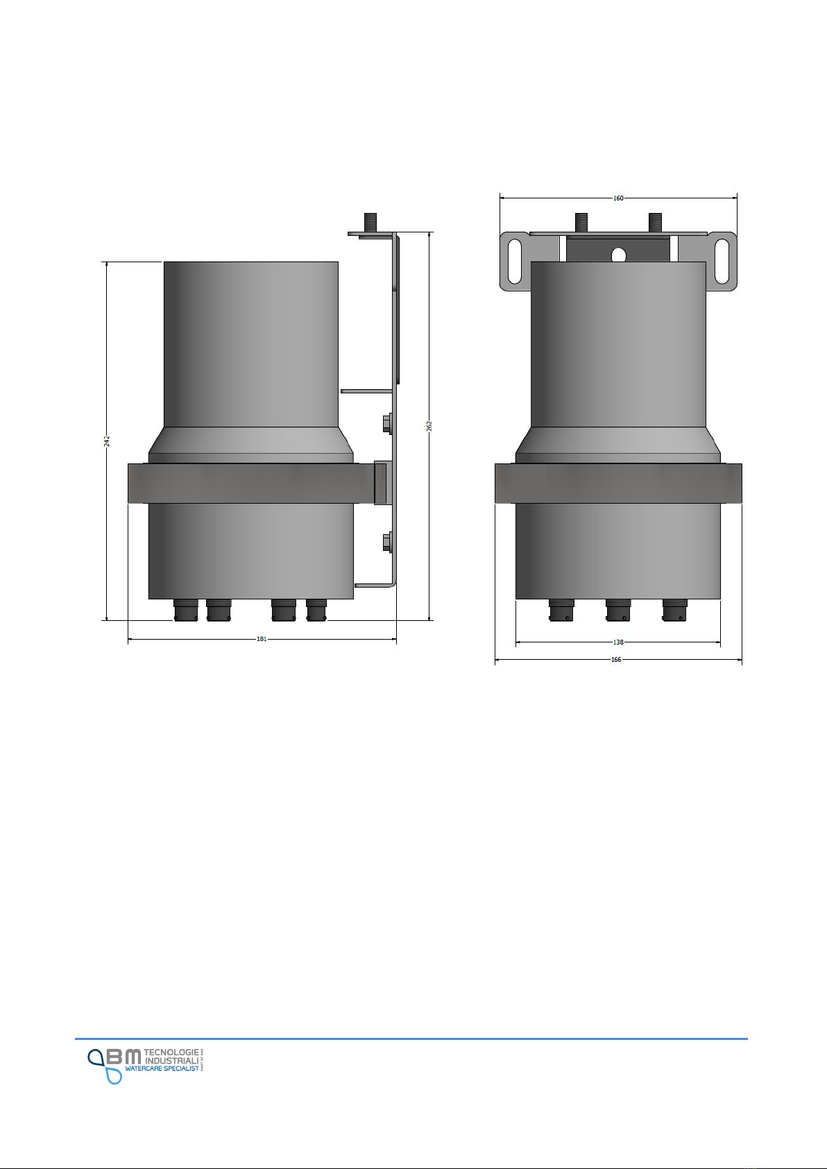
Weights and Dimensions
H242 mm X D166 mm –1,8 Kg (mounting system NOT included)
Connectors
Water proof, military type
COMPLIANCE
Electrical safety
Directive 2014/35/EU "low Tension”
Eelectromagnetic
compatibility
Directive 2014/30/EU "Radio Machinery"
Telecommunications
Directive 2014/53/EU "Telecommunication Terminals"
3.4 Functional features
FUNCTIONAL FEATURES of KAPTORMINI
CONFIGURATION
Through a free of charge AndroidTM app, the user can setup the device with a simple and intuitive
interface typical of modern apps. In, the user can download data and events, monitor the values read,
diagnose the device. Kaptor mini is connected to the user's device (tablet, smartphone) via a secure Wi-
Fi connection.
The downloaded files are in CSV format, easily processed in Excel.
Via Remote system (under development)
DIAGNOSTICS
Through signal leds
By checking the case’s mechanical and environmental conditions
By sending through modem the closing and covering GPRS conditions
DATA ACQUISITION
Data of every I/O are saved in the circular memory buffer. Time interval is set by the user: from 1 to 60
minutes.
Variable reading data are saved on a cyclic buffer of 255 events.
Sensors warm-up times are user set for every I/O.

KAPTOR MINI –User Manual –V0.1 - pg.12
I/O CONFIGURATION
Analog inputs: measuring range, entering a linearization curve on 16 points, entering offset. Calibration
on low and full range. Current or voltage input selection.
Digital counter inputs: pulse weight, counter increase, calculation of average pulses in the unit of time
Event digital inputs: check on/off status (activation), log status, sampling rate change on event.
RS485 port: complete configuration of the connected sensor, reading of variables, flow calculation (with
sensors for flow measurements).
Relay: configuration for alarm signaling and cleaning function (cleaning system not included).
EVENT MANAGEMENT
Alarm events on each of the variables read by the device. Each event is associated with an alarm message
which is recorded in memory and can be sent via SMS or GPRS.
Diagnostic events: case closure, GPRS network, internal board status.
CONNECTIVITY TO A REMOTE SERVER
Proprietary communication protocol: data sending to a remote server using a proprietary
communication protocol with http service via GET. The protocol can be provided to the user for the
development of the driver for receiving data on his server.
FTP: the data is sent by transferring a CSV file, with FTP protocol, to a folder of an accessible remote
device.
Ability to select 2G or 3G network depending on coverage.
Automatic search for the best operator (with multi-operator SIM).
Possibility to identify the IMEI of the modem and IMEI of the SIM.
DATA TRANSMISSION
Saved data from the oldest to the last one.
Data transmission frequency from 1 to 24 hours.
ALARMS
Alarms transmission to a remote server. Historical data transmission when alarm occurs.
DIAGNOSTICS
Diagnostics transmission to a remote server: all diagnostics parameters referring to the device’s status
are sent to the remote server.
CONFIGURATION TRANSMISSION
Configuration parameters are sent to check the configuration/setup remotely.

KAPTOR MINI –User Manual –V0.1 - pg.13
SMS
Alarm events can be sent via SMS to 3 users max. If the transmission fails, the device could be setup to
retry sending SMS to selected intervals.
DATE/TIME SYNCHRONIZATION
If enabled, the device can synchronize the date and time of its internal clock with that of the server to
ensure that multiple instruments can have the same time.
If enabled, time can be synchronized to a remote NTP server.
CLEANING CYCLES
Cleaning cycles for the sensors connected to the device can be programmed. The cleaning cycle consists
of activating a relay output for a set time, waiting for a post-cleaning time and logging the sensor
variables. This function can be particularly useful if sensors need cleaning before to be read.
KAPTOR MINI –User Manual –V0.1 - pg.14
4Dimensions and fixing system
KAPTOR MINI was designed to be wall mounted with a bracket made of stainless steel. The bracket keeps
the device in vertical position in order to reach external connectors easily.
KAPTOR MINI –User Manual –V0.1 - pg.15
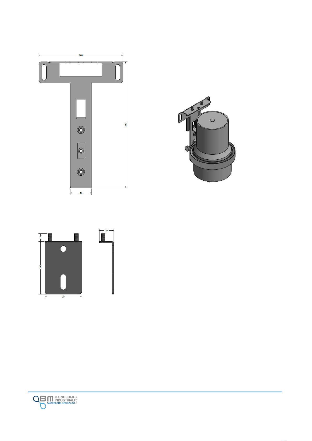
4.1 Mouting bracket
This bracket is used to hook up the device through the closing
clamp.
The bracket can be wall mounted by using two plugs (hole
diameter in the bracket is 10mm).
4.2 Quick release wall mounting support
If you plan to replace the device frequently, it is possible to use a
wall support that allows the quick release of the mounting
bracket.
Once fixed to the wall with two dowels, the bracket simply hooks
from above by inserting the two holes in the threaded stubs at the
top and screwing the two nuts.
This support is also particularly suitable when using external
batteries, in order to simplify their replacement.
KAPTOR MINI –User Manual –V0.1 - pg.16
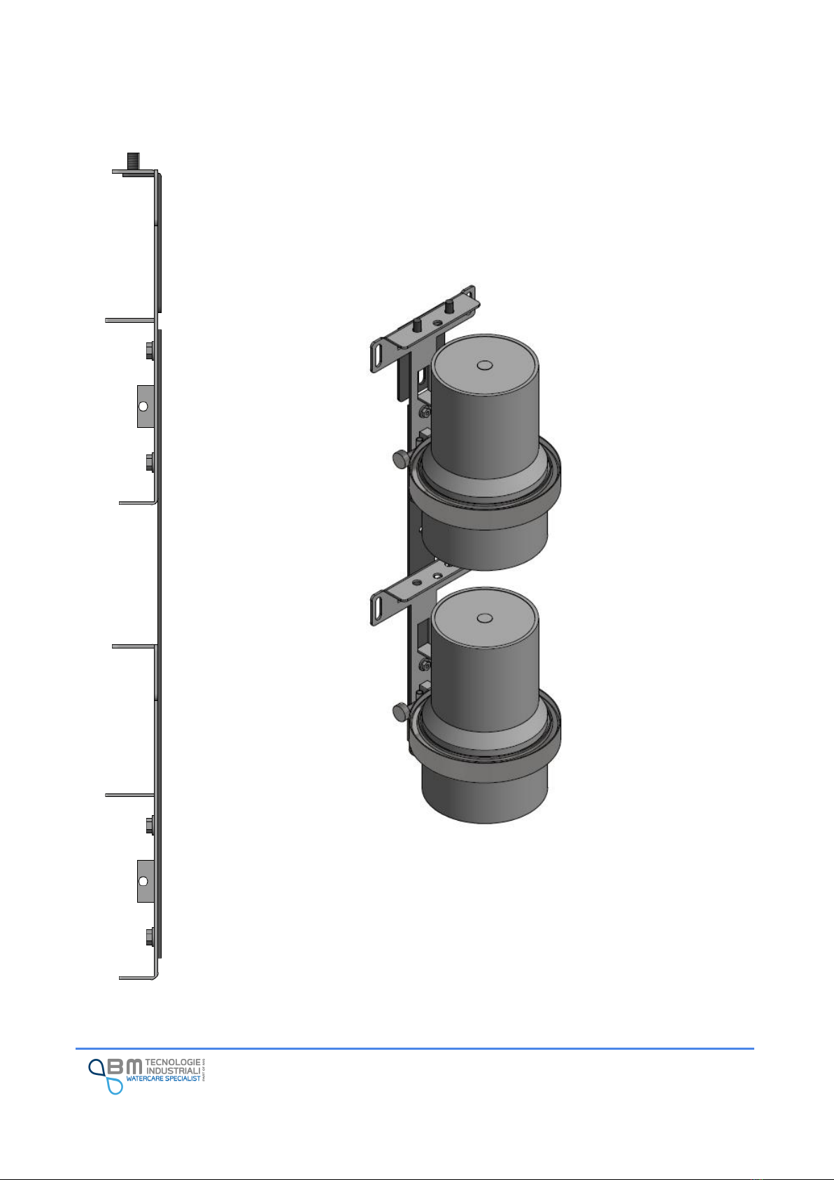
4.3 Combined mounting bracket
If your device has an external battery, or in other peculiar cases including two devices, a
combined mounting system is foreseen. It consists of two brackets with a coupler.
The coupler allows two mounting brackets to be hold together, in order to reduce installation
space and use a single quick-release system.

KAPTOR MINI –User Manual –V0.1 - pg.17
5Case opening and closure
In standard operating conditions, it is not necessary to open or close the KAPTOR MINI case.
But it could be in these cases:
✓Primary battery replacement
✓SIM card Installation/replacement/removal
✓Data transmission Antenna replacement
If necessary, unscrew the collar external clamp nut and use the quick-release system to remove the
device.
Once the clamp is removed, separate the two parts of the case. The O-rings guarantee the degree of
protection IP68 so it is completely normal to find resistance in this phase. If so, you can help yourself by
levering with two flat screwdrivers.
To close bring the two parts of the case closer so that they fit together. Pay attention to any wires: do not
press them between the parts of the case itself or of the internal components. Install the locking collar
and tighten the nut.
The correct tightening is done by applying a force of 9Nm and, in any case, when the two parts of the case
come into contact.
Before closing the case you have to check if all connections (internal battery, antenna…) are
ok.
A torque wrench can be supplied by B.M. Tecnologie Industriali on request.

KAPTOR MINI –User Manual –V0.1 - pg.18
The IP68 protection degree of the case is guaranteed by two O-rings: before closing, check
that they are present, correctly positioned, lubricated and not damaged. Cracks, cuts and
deformations can seriously affect the IP68 seal of the case.
Long periods of closure, exposure to high or low temperatures are natural conditions of
deterioration of the O-rings
In the event of damage, it is necessary to replace them by requesting them from the assistance
service.
A drying bag is necessary to remove any residual moisture, place it inside the case before
closing. It is possible to request a desiccant kit from the assistance service.
O-rings and drying bags must be replaced every time the case is opened.
B.M. Tecnologie Industriali is not liable for any damage caused by failure to keep the case due
to non-compliance with the indicated requirements.

KAPTOR MINI –User Manual –V0.1 - pg.19
6Power supply
KAPTOR MINI can be powered via 2 inputs. One with 3.6Vdc voltage and one with 8..24Vdc. The power
sources can be battery (rechargeable or primary) or a power supply on site with working voltage in the
declared range. The batteries can be connected externally through a special connector or placed inside
the case in the appropriate battery holder.
B.M. Tecnologie Industriali supplies different external and internal battery technologies to cover the
different fields of application of the device. External batteries is connected with a dedicated cable to
facilitate the user for quick replacement without opening the device.
The range of batteries used and supplied by B.M. Tecnologie is wide and not limited to those
listed below, to guarantee compatibility with the most different installations. Please refer to
any additional documentation attached regarding the supplied battery.
Disassembling the battery pack, replacing cells, attempting to recharge non-rechargeable
batteries or using unsuitable chargers can cause serious damage to the battery, things and
people.
B.M. Tecnologie Industriali is not liable for any damage caused by incorrect installation and/or
use.
6.1 Primary internal battery (not rechargeable) –3,6V
Chamical
component
Lithium
Tension
3,6V
Capacity
38AH or higher
Sensors
Power supply of digital/analog inputs and built-in pressure sensor. It cannot supply
sensors connected to RS485.
Main
Application
Long time monitoring activities (i.e. 4 years) with low power sensors connected to
analog/digital inputs.
6.1.1 Internal battery replacement
Kaptor Mini can be equipped with an Internal Battery of 3,6V.
Follow these steps for battery replacement:
1. Open the case by using the external collar;
2. Pay attention to the cable to the antenna (if the device has a built-in antenna);
Table of contents


