Marquis M G 1 9 3 2 User manual

User’s Guide
MARQUIS GALAXY
MGSERIES
MG1932
M G 191 8 S
MG1915M
MG192 8
M G 1928- W H
MG1915 S
M G - A F
MG-SM A F

2

CONTENTS
10. Use only with a cart, stand, bracket, or table specified by the
manufacturer or sold with the apparatus. When a cart is used, use
caution when moving the cart / apparatus combination to avoid
injury from tip-over.
11. Refer all servicing to qualified service personnel.
Servicing is required when an apparatus has been
damaged in any way, such as power-cord or plug
is damaged, liquid has been spilled, or objects
have fallen into the apparatus, the apparatus has
been exposed to rain or moisture, does not
operate normally, or has been dropped.
12. To reduce the risk of fire or electric shock, do not expose this
apparatus to rain or moisture.
13. Hearing damage, prolonged exposure to excessive SPL, the
loudspeaker is easily capable of generating sound pressure levels
(SPL) sufficient to cause permanent hearing damage to performers,
production crew and audience members. Caution should be taken
to avoid prolonged exposuro SPL in excess of 90 dB.
IMPORTANT SAFETY INSTRUCTIONS
The MG Series loudspeakers covered by this manual are not intended for fixed installation in outdoor or high
moisture environments. Moisture can damage the speaker cone and surround and cause corrosion of electrical
contacts and metal parts. Avoid exposing the speakers to direct moisture. Keep speakers out of extended or
intense direct sunlight. The driver suspension will prematurely dry out and finished surfaces may be degraded by
long-term exposure to intense ultra-violet (UV) light.
The MG Series speakers can generate considerable energy. When placed on a slippery surface such as
polished wood or linoleum, the speaker may move due to its acoustical energy output. Precautions should be
taken to assure that the speaker does not fall off a stage or table on which it is placed.
PATENTS
MG series products are manufactured and sold under U.S. patents 5,748,760; 6,112,847; 6,394,223; 6,847,726;
6,774,510; D483,743; 6,768,806; and D483,744.
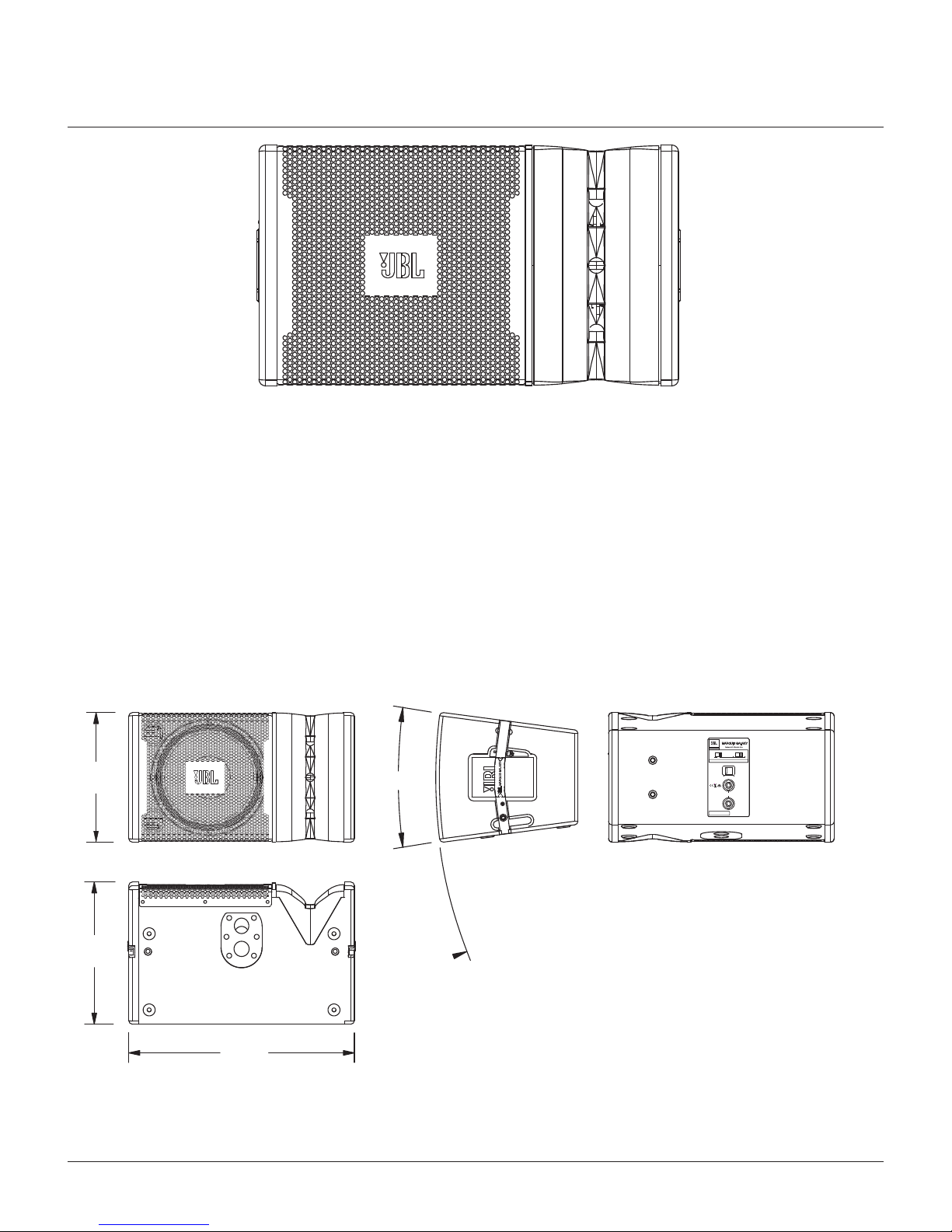
4MG1932ehtotnoitcudortnI
5MG1932 Specifications
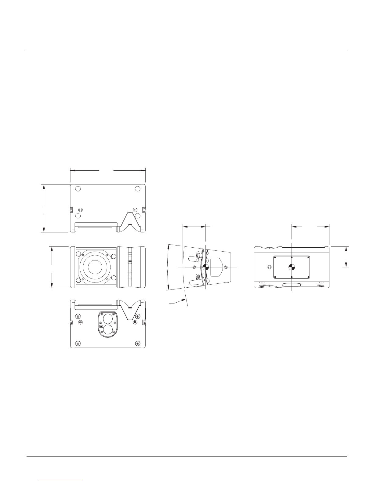
6MG1928ehtotnoitcudortnI
7MG1928 Specifications
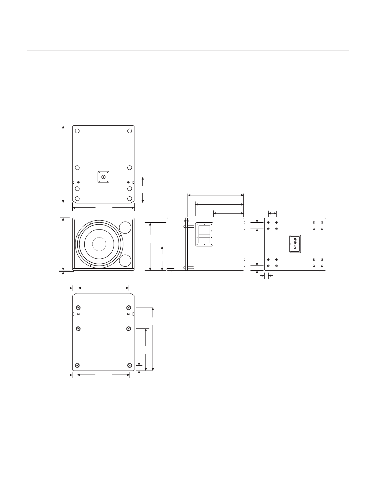
8MG1918SehtotnoitcudortnI
9MG1918S Specifications
01MG1915SehtotnoitcudortnI
11MG1915S Specifications
21MG1915Mehtot
noitcudortnI
31MG1915M Specifications
51-41gnidahSedutilpmA
51sgninuTrossecorPmetsyS
71-61metsySehtgniyolpeD
02-81sgninraWytefaSnoisnepsuS
12MG-AFehtotnoitcudortnI
22MG-SMAFehtotnoitcudortnI
32ytnarraWLBJ
1. Read these instructions.
2. Keep these instructions.
3. Heed all warnings.
4. Follow all instructions.
5. Do not use this apparatus near water.
6. Clean only with a dry cloth.
7. Do not block any ventilation openings. Install in accordance
with manufacturer’s instructions.
8. Do not install near any heat sources such as radiators, heat
registers, stoves, or other apparatus that produce heat.
9. Only use attachments / accessories specified by the manufacturer.
3

INTRODUCTION TO THE MG1932
The MG1932 is a two-way, line-array loudspeaker system intended for use in arrays of up to six enclosures.
Three high-frequency drivers are mounted to the Constant Curvature waveguide which is designed so that
multiple enclosures may be arrayed with no discontinuity in the vertical coverage pattern. As a result, the array
will behave in much the same way as would a single loudspeaker. Array coverage may be adjusted by means
of the Array Configuration Selector (ACS), a feature that provides amplitude shading (see page 14 & 15) when
the system is used in passive mode. Integral rigging hardware, a dual angle pole socket and an accessory array
frame provide for a variety of mounting and suspension options.
DIMENSIONAL DRAWINGS FOR MG1932
4
349
(13.75)
376
(14.8)
15°
R:1325
(52.2)
597
(23.5)
Dimensions in mm (inches)
JBLPROFESSIONAL
Northridge, CA USA
Madein USA
Serial No.
BI-AMP
PASSIVE
PARALLEL
MG1932
BI-AMP
±1 LF: 8
±2 HF: 6
Ω
Ω
PASSIVE
±1 IN: 6
±2 N/C
Ω
Single
Speaker
or
Short
Throw
Mid
Throw
Long
Throw
Array Configuration Selector - HF Output Level
TransducerTechnologyU.S. PATENT 5,748,760
MARQUIS GALAXY

SPECIFICATIONS
MG1932 - 12”, TWO-WAY, LINE ARRAY LOUDSPEAKER SYSTEM
metsysrekaepsduolyarraenil,yaw-owt"21:epyTmetsyS
Frequency Range (-10 dB) 1: 57 Hz - 20 kHz
Frequency Response (±3 dB)1: 75 Hz - 20 kHz
)lacitrevxlatnoziroh(lanimon5°1x0°01:nrettaPegarevoC
elbahctiwsyllanretxe,evissap/pma-iB:sedoMrevossorC
Crossover Frequency: 1.2 kHz
W0023/W0061/W008:evissaPgnitaRrewoP
(Continuous 2 / Program / Peak): Bi-amp LF: 800 W / 1600 W / 3200 W
Bi-amp HF: 75 W / 150 W / 300 W
System Maximum SPL 3: 130 dB SPL peak (passive)
LF: 130 dB
HF: 139 dB
System Sensitivity (1w @ 1m): 95 dB SPL (passive mode)
LF: 95 dB
HF: 114 dB
evirDlaitnereffi
D)ni21(mm503H262
2LBJx1:revirDFL ®woofer with
neodymium-magnet and dual voice-coils
tengammuimydoen,lioc-eciov)ni5.1(mm83,J8042LBJx3:revirDFH
compression driver
Nominal Impedance: Passive: 8 ohm
Bi-amp LF: 8 ohms
Bi-amp HF: 8 ohms
moc.orplbj.wwwtaelbaliavasgninuT:sgninuTevitcA
.doowylphcribylp-11,mm81:erusolcnE
Suspension / Mounting 4: Suspension requires optional MG-AF line array frame kit /
Dual angle 36 mm pole socket / 10 mm eyebolt
Finish 5hsinif™xelFaruDkcalB:
Grille 6yllacitsuocahtiwleetsdetarofrepeguag-61,kcalb,detaocredwoP:
transparent foam
kirtueN:srotcennoCtupnI ®Speakon®NL-4 (x2)
Dimensions (H x W x D): 349 mm x 597 mm x 376 mm (13.75 in x 23.5 in x 14.8 in)
)bl64(gk12:thgieWteN
Optional Accessories: MG-AF: Suspension array frame
SS2-BK: Tripod speaker stand
SS3-BK: Satellite Speaker Pole
SS4-BK: Adjustable Satellite Speaker Pole to be used with MG1918S and
SRX718S only.
M10 Eyebolt Kit (Part # 229-00009-01)
FUNCTIONAL BLOCK DIAGRAM
1. “Frequency Range” and “Frequency Response” are based on half-space conditions.
2. IEC filtered noise with 6 dB crest factor, 2 hours.
3. Calculated based on power rating and sensitivity.
5
SHORT THROW
MID THROW
LONG THROW
1+
1-
2-
2+
1+
1-
2-
2+
NL4
INPUT
NL4
INPUT
HPF
LPF
PASSIVE
MODE
-3 dB
0 dB
+3 dB
+
+
+
+
-
-
-
-
1+
1-
2-
2+
1+
1-
2-
2+
BI-AMP
MODE
NL4
INPUT
NL4
INPUT
+
+
+
+
-
-
-
-

INTRODUCTION TO THE MG1928
NOTE: A white version is available for this product through our custom shop.
Contact your JBL dealer or rep. for details
DIMENSIONAL DRAWINGS FOR MG1928
The MG1928 - the smaller version of the MG1932 is a light-weight, compact, 8”, two-way line-array speaker
system system designed for use in arrays of up to six units. MG1928 is the ideal choice when line-array perfor-
mance is needed but the venue size doesn't call for the very long-throw characteristics of larger line-arrays. The
MG1928 offers all the same features as the MG1932. As with the MG1932, the Array Configuration Selector
(ACS) makes it possible to distribute the sound more evenly over the entire audience area, by reducing the
output near the stage and increasing it for the far to reach rear areas. (See page 14 & 15)
Dimensions in mm (inches)
6
267
(10.5)
230
(9)15°
876
R:34.5
127
(5.0)209
(8.3)
115
(4.5)
419
(16.5)

SPECIFICATIONS
MG1928 - 8”, TWO-WAY, LINE-ARRAY SPEAKER
metsysrekaepsduolyarraenil,yawowt"8:epyTmetsyS
Frequency Range (-10 dB): 70Hz -20kHz
Frequency Response (±3 dB): 87Hz - 19kHz
tinuelgnis,)lacitrevxlatnoziroh(lanimon5°1x0°01:nrettaPegarevoC
elba-hctiwsyllanretxe,evissap/pma-iB:sedoMrevossorC
Crossover Frequency: 2.0 KHz
Power Rating 1W0061/W008/W004:
(Continuous / Program / Peak) Bi-amp LF: 400 W / 800 W / 1600W
Bi-amp HF: 30 W / 60 W / 120 W (two drivers)
System Maximum SPL 2: 122dB SPL (passive mode)
LF: 122 dB
HF: 128 dB
System Sensitivity (1 W @ 1m) 90 dB SPL (passive mode)
LF: 90 dB
HF: 108 dB
evirDlaitnereffiD)ni8(mm002,1-H86
12LBJx1:revir
DFL ®woofer
revirdnoisserpmocmuimydoen)ni0.1(mm52,H4142LBJx2:revirDFH
Nominal Impedance: Passive: 8 Ohms
Bi-amp LF: 8 Ohms
Bi-amp HF: 16 Ohms
moc.orplbj.wwwtaelbaliavasgninuT:sgninuTevitcA
doowylphcribylpitlum,mm52-mm51:erusolcnE
Suspension / Mounting: Dual 36mm pole socket included. Suspension requires optional
MG-SMAF line array frame kit or 10mm eyebolt.
pucgnikcabhtiweldnahdetargetnI:tropsnarT
hsinif™xelFaruDkcalB:hsiniF
lacitsuocahtiwleetsdetarofrepeguag81,kcalb,detaocredwoP:ellirG
transparent black foam backing.
kirtueNx2:srotcennoCtupnI ®Speakon NL-4
Dimensions (H x W x D): 230 mm x 419 mm x 267 mm (9 in x 16.5 in x 10.5 in)
).bl82(gk7.21:thgieWteN
Optional Accessories: MG-SMAF: Suspension array frame
SS2-BK: Tripod speaker stand
Eyebolt Kit (Part # 229-00009-01)
FUNCTIONAL BLOCK DIAGRAM
1 IEC filtered noise with 6 dB crest factor, 2 hours.
2 Calculated, based on power rating and sensitivity.
7

INTRODUCTION TO THE MG1918S
The MG1918S is a compact, single, 18"direct radiating subwoofer intended for use in suspended arrays or
ground-supported applications. The suspension system is designed for full compatibility with the MG1932
line-array speaker system and the MG-AF array frame.
DIMENSIONAL DRAWINGS FOR MG1918S
Dimensions in mm (inches)
8
749
(29.5)
597
(23.5)
254
(10.0)
508
(20.0)
8
(0.3)
457
(18.0)
235
(9.25)
546
(21.5)
464
(18.25)298
(11.75)
60
(2.37)
44
(1.75)
38
(1.5)
79
(3.13)
56
(2.2)
489
(19.25)
45
(1.8)
508
(20.0)51
(2.0)
406
(16.0)
610
(24.0)

SPECIFICATIONS
MG1918S - 18” , BASS-REFLEX SUBWOOFER
MG1918S
1. “Frequency Range” and “Frequency Response” are based on half-space conditions.
2. IEC filtered noise with 6 dB crest factor, 2 hours.
3. Calculated based on power rating and sensitivity.
refoowbusxelfer-ssab"81:epyTmetsyS
Frequency Range (-10 dB) 1: 31 Hz - 220 Hz
Frequency Response (±3 dB)1: 34 Hz - 220 Hz
Input Connection Modes: Switchable, +1/-1 or +2/-2
Recommended Crossover: High-pass: Butterworth 18 dB/oct, 31 Hz
Low-pass: Linkwitz-Riley 48 dB/oct, 80 Hz
W0023/W0061/W008gnitaRrewoP
(Continuous 2 / Program / Peak)
Maximum SPL 3kaepLPSBd031:
Sensitivity (1w @ 1m): 95 dB SPL
refoowevirDlaitnereffiD)ni81(mm754H8622LBJx1:revirDFL
Nominal Impedance: 8 ohms
sgninutS817XRSesU:sgninuTevitcA
Mounting 4MG-AF line array frame kit or 10mm eyeboltlanoitpO:
(Part #229-00009-01)
Suspension / Mounting: Top mounted M20 threaded socket for optional SS4-BK pole
doowylphcribylp-31,mm81,ralugnatceR:erusolcnE
Finish 5hsinifxelFaruDkcalB:
Grille 6tnerapsnartlacitsuocahtiwleetsdetarofrepeguag-61,detaocredwoP:
charcoal foam backing.
kirtueN:srotcennoCtupnI ®Speakon®NL-4 (x2)
Dimensions (H x W x D): 508 mm x 597 mm x 749 mm; (20.0 in x 23.5 in x 29.5 in)
)bl18(gk73:thgieWteN
Optional Accessories: SRX718S-CVR: Pull-over padded cover
SS4-BK: Adjustable, heavy-duty pole,
M20 thread to 35 mm pole mount
WK-4: Caster kit
MG-AF Array Frame
Eyebolt Kit (Part #229-00009-01)
9
FUNCTIONA BLOCK DIAGRAM
JBL PROFESSIONAL
Northridge, CA USA
Serial No.
NL4 ±1
NL4 ±2
MG1918S
IN / THRU
Marquis Galaxy
8Ω
WARNING: Do not attempt to suspend unless you
have read and fully understood all instructions.
Follow all applicable local ordinances. Attachment of
the loudspeaker to supporting structure should be
referred to a qualified professional.
Equipped with Differential Drive
®
Transducer
Technology U.S. PATENTS: 5,748,760, 6,768,806,
6,847,726, 6,774,510 and D483,743.
Designed in the USA
Assembled by JBL in Mexico

INTRODUCTION TO THE MG1915S
The MG1915S a very compact single 15"direct radiating subwoofer is intended as companion subwoofer
for the MG1928. The suspension system is designed for full compatibility with the MG1928 Line Array
System and with the MG-SMAF array frame. The M20 mounting plate allows for utilization of the adjustable
pole mount SS4-BK.
WARNING: The MG1928 is the only system intended for use with the MG1915S when utilizing the SS4-BK.
DIMENSIONAL DRAWINGS FOR MG1915S
Dimensions in mm (inches)
10
31.4
(12.4)
4
(1.6)
318
(12.5)
478
(18.8)
597
(23.5)
500.13
(19.7)
496
(19.5)
420
(16.5)
478
(18.8)
328.24
(12.9)
248
(9.8)43
(1.7)
43
(1.7)

SPECIFICATIONS
MG1915S - 15”, BASS-REFLEX SUBWOOFER
51:epyTmetsyS "bass reflex subwoofer
Frequency Range (-10 dB): 35Hz -250Hz
Frequency Response (±3 dB): 40Hz - 250Hz
Recommended Hi-Pass Filter: HP: Butterworth 24 dB/octave, 45 Hz
LP: Linkwitz-Riley 48 dB/octave, 80 – 120Hz
Power Rating 1:
(Continuous / Program / Peak) 800 W / 1600 W / 3200W
Recommended EQ: +2dB at 45Hz, Q: 2.5
Maximum SPL 2: 126 dB SPL
Sensitivity (1 W @ 1m) 91 dB SPL
evirDlaitnereffiD)ni51(mm052,1-G5622LBJx1:revirDFL ®woofer
Nominal Impedance: 4 Ohms
moc.orplbj.wwwtaelbaliavasgninuT:sgninuTevitcA
doowylphcribylpitlum,mm81-mm51:erusolcnE
Suspension / Mounting: Top mounted M20 threaded socket for optional pole SS4-BK. Integrated
flying hardware for use with array frame MG-SMAF.
Optional M10 eyebolt kit.
pucgnikcabhtiweldnahleetsdetargetnI:tropsnarT
hsinif™xelFaruDkcalB:hsiniF
lacitsuocahtiwleetsdetarofrepeguag81,kcalb,detaocredwoP:ellirG
transparent black foam backing.
Input Connectors: 2x Neutrik®Speakon NL-4
Input connection modes: Switchable, +1/-1 or +2/-2
Dimensions (H x W x D): 496 mm x 420 mm x 597 mm (19.5 in x 16.5 in x 23.5 in)
).bl75(gk62:thgieWteN
Optional Accessories: SS4-BK: Adjustable, heavy-duty pole,
M20 thread to 35 mm pole mount
WK-4: Caster kit
MG-SMAF Array Frame
Eyebolt Kit (Part #229-00009-01)
FUNCTIONAL BLOCK DIAGRAM
1 IEC filtered noise with 6 dB crest factor, 2 hours.
2 Calculated, based on power rating and sensitivity.
11
JBL PROFESSIONAL
Northridge, CA USA
Serial No.
NL4 ±1
NL4 ±2
MG1915S
IN / THRU
4Ω
WARNING: Do not attempt to suspend unless you
have read and fully understood all instructions.
Follow all applicable local ordinances. Attachment of
the loudspeaker to supporting structure should be
referred to a qualified professional.
Marquis Galaxy
Equipped with Differential Drive®Transducer
Technology U.S. PATENTS: 5,748,760, 6,768,806,
Designed in the USA
Assembled by JBL in Mexico
6,847,726, 6,774,510 and D483,743.

INTRODUCTION TO THE MG1915M
The MG1915M is a dedicated, compact and lightweight, 15", two way touring-class floor monitor, with only
a 375 mm (14.75 in) stage height and JBL’s latest neodymium-magnet transducers.
A 380 mm (15 in) 2265H patented Differential Drive®woofer handles 800 watts (continuous) and delivers
accurate and precise low frequency reproduction. The 2452H 102 mm (4 in) voice-coil compression driver is
coupled to a 50° x 90° aluminum horn to provide smooth and clear high frequency reproduction, critical for high
performance monitoring.
Bi-amp or full-range passive operation may be selected via a recessed, high-current switch mounted alongside
the NL4 input connector in one of the handle cups. An additional NL4 connector is mounted in the other handle
cup for a convenient loop-thru connection, minimizing cable runs on stage.
The enclosure is constructed of top quality Baltic birch plywood and is coated in JBL’s rugged DuraFlex™
finish. It is a symmetrical 30° wedge design, with four non-slip rubber feet per side enabling convenient left and
right applications of adjacent monitors. The transducers are protected by an attractive 16 gauge CNC-machined
steel grille, which is internally lined with acoustically transparent foam to provide additional transducer protection.
DIMENSIONAL DRAWINGS FOR MG1915M
12
Dimensions in mm (inches)
324
(12.75)
432
(17.00)
629
(24.75)
159
(6.25)
375
(14.75)
546
(21.51)
191
(7.51)
Dimensions in mm (inches)

SPECIFICATIONS
MG1915M - 15”, TWO-WAY STAGE MONITOR
rotinoMegatSyaw-owT"51:epyTmetsyS
Frequency Range (-10 dB): 60 Hz - 20 kHz
Frequency Response (±3 dB): 70 Hz - 20 kHz
Coverage Pattern: 50° x 90° nominal
Crossover Modes: Passive / Bi-amp
Crossover Frequency: 1.1 kHz
srh2,W0023/W0061/W008egnaR-lluFevissaP:gnitaRrewoP 1
(Continuous / Program / Peak) Bi-amp LF: 800 W / 1600 W / 3200 W, 2 hrs 1
Bi-amp HF: 75 W / 150 W / 300 W, 2 hrs 1
)kaepLPSBd331(suounitnocLPSBd721:LPSmumixaM 2
System Sensitivity (1w @ 1m): 98 dB SPL
evirDlaitnereffiD)ni51(mm083,H5622LBJx1:revirDFL ®woofer 8 Ohms
,tixe)hcni5.1(mm83,lioceciovretemaid)
hcni0.4(mm001,H2542LBJx1:revirDFH
neodymium magnet compression driver 8 Ohms
Nominal Impedance: 8 Ohms Full-Range Passive
mth.xedni/sgninut/moc.orplbj.www//:ptthtaelbaliavasgnitteS:sgninuTevitcA
.doowylphcriB,mm81/51,rotinomegatslacirtemmyS:erusolcnE
puctupni/eldnahdetargetnIx2:tropsnarT
hsinif™xelFaruDkcalB:hsiniF
tnerapsnartyllacitsuocahtiwleetsdetarofrepeguag61,kcalb,detaocredwoP:ellirG
black screen backing.
Input Connectors: Neutrik®Speakon®NL-4 (x2), one on each end
Dimensions (H x W x D): 629 mm x 432 mm x 324 mm (375 mm stage height)
24.75 in x 17 in x 12.75 in (14.75" stage height)
)bl0.64(gk12:thgieWteN
FUNCTIONAL BLOCK DIAGRAM
1. IEC standard, full bandwidth pink noise with 6 dB crest factor for specified period
2. Calculated based on power rating and sensitivity.
JBL continually engages in research related to product improvement. Some materials, production methods and design refinements are introduced
into existing products without notice as a routine expression of that philosophy. For this reason, any current JBL product may differ in some respect
from its published description, but will always equal or exceed the original design specifications unless otherwise stated.
-
+
+
-
HIGH
FREQ
HIGH
FREQ
+
-
+
-
LOW
FREQ
LOW
FREQ
1+
1-
2-
2+
1+
1-
2-
2+
1+
1-
2-
2+
1+
1-
2-
2+
NL4
IN / THRU
NL4
IN / THRU
NL4
IN / THRU
NL4
IN / THRU
HPF
PASSIVE
MODE
BI-AMP
MODE
LPF
13
BI-AMP
PASSIVE
MG1915M
BI-AMP
±1 LF: 8
±2 HF: 8
Ω
Ω
PASSIVE
±1 IN: 8
±2 N/C
Ω
JBL PROFESSIONAL
Northridge, CA USA
®
Transducer
Technology U.S. PATENTS: 5,748,760, 6,768,806,
6,847,726, 6,774,510 and D483,743.
Designed in the USA
Assembled by JBL in Mexico
Marquis Galaxy
BI-AMP
PASSIVE
MG1915M
BI-AMP
±1 LF: 8
±2 HF: 8
Ω
Ω
JBL PROFESSIONAL
Northridge, CA USA
Equipped with Differential Drive
®
Designed in the USA
Assembled by JBL in Mexico
Serial No.
MG1915M
BI-AMP
±1 LF: 8
±2 HF: 8
Ω
Ω
PASSIVE
±1 IN: 8
±2 N/C
Ω
JBL PROFESSIONAL
Northridge, CA USA
Designed in the USA
Assembled by JBL in Mexico
BI-AMP
PASSIVE
Marquis Galaxy

AMPLITUDE SHADING
AMPLITUDE SHADING
Amplitude shading is a technique that allows the coverage pattern of a loudspeaker array to be shaped by
adjusting the relative acoustic output of some of the devices in the array. Most often, array shading involves
only the mid and high-frequency sections of the array. In a simple system consisting of three MG1932 /
MG1928s, the lower speaker (which covers the nearest listeners) may have its high-frequency output reduced.
At the same time, the upper speaker may have its high frequency output increased. The overall sound-power
in the room is unchanged but the distribution of acoustic energy to the audience is far more uniform.
Amplitude shading of an MG1932 / MG1928 array may be accomplished in passive or bi-amplified systems.
ARRAY CONFIGURATION SELECTOR (ACS)
In passive mode, the Array Configuration Selector may be used. The -3 dB position will typically be used for
the speaker(s) in an array that are covering the nearest listening area. The +3 dB position will be used for the
speaker(s) covering the more distant areas; or to compensate for the low-frequency build-up resulting from
mutual coupling of multiple woofers in an array.
Short Throw (-3 dB) Long Throw (+3 dB)Medium Throw (0 dB)
FREQUENCY RESPONSE
The frequency response graph represents measurements from a single typical MG series speaker, applying the
three different ACS settings: +3dB, 0dB, -3dB.
14

BI-AMPLIFIED SYSTEM
In a bi-amplified system, array shading is accomplished by connecting separate amplifier channels to the HF
section of each MG1932 / MG1928. In larger arrays, a single amplifier channel may be used for two adjacent
loudspeakers. Array shading is then accomplished by adjusting the gain of the HF amplifier channels.
For extremely precise control over system performance, it may also be desirable to dedicate an individual
system controller output to each HF amplifier channel.
ARRAY CONFIGURATION SELECTOR (ACS)
Below is an example of applying the ACS in a three-speaker array. In this particular configuration, the ACS on
the top speaker is set at +3 dB, the middle speaker at 0 dB, and the bottom speaker -3 dB.
Please visit www.jblpro.com/tunings for latest versions of our recommended system tunings or call customer
service at Toll Free 1-800-852-5776.
SYSTEM PROCESSOR TUNINGS
15
+3 dB
0 dB
-3 dB
Audience

DEPLOYING THE SYSTEM
The MG1932 is a flexible speaker system that can be deployed in ground-supported or suspended applications.
The following information will help you set up your MG1932 system safely and effectively.
POLE AND TRIPOD SAFETY WARNINGS!
When using stands or poles, be sure to observe the following precautions:
•Check the stand or pole specification to be certain the device is designed to support the weight of
the speaker. Observe all safety precautions specified by the manufacturer.
•Be certain that the surface on which the system is to be stacked is flat, stable and solid.
•Route cables so that performers, production crew, and audience will not trip and topple the speakers.
•Inspect the stand (or pole and associated hardware) before each use and do not use equipment with
worn, damaged, or missing parts.
•Do not attempt to place more than two MG1932 loudspeakers on a stand or pole.
•When mounting two MG1932 speakers on a pole or tripod, integral rigging hardware must be used
to secure the speakers to each other.
•Always be cautious when deploying the system outdoors. Unexpected winds may topple a system.
It may be necessary to place additional weight (i.e.sandbags) on the base of the stand to improve
stability. Avoid attaching banners or similar items to any part of a speaker system. Such attachments
could act as a sail and topple the system.
•Unless you are confident that you can handle the weight of the speaker, ask another person to help
you get it onto the tripod stand or pole.
•One or two MG1932 cabinets may be mounted onto either a JBL SS2-BK tripod stand or with the
SS4-BK adjustable pole mount to their companion MG1918S or SRX718S subwoofers. Do not mount
MG1932 cabinets on top of the compact MG1915S subwoofer!
•One or two MG1928 cabinets maybe mounted onto either a JBL SS2-BK tripod stand or their
companion subwoofer MG1915S. The larger type subwoofer SRX718S / MG1918S can also be used.
SINGLE MG1932 / MG1928
A single MG1932 may be used on a tripod stand (JBL SS2-BK) or on a
pole (JBL SS4-BK) over its companion subwoofer the MG1918S or the
SRX718S. The use of a subwoofer is recommended for applications requiring
more low-frequency power and extension. Usually, the Array Configuration
Selector (ACS) switches on the input panel should be set to the “Short Throw
(-3 dB)” position when a single speaker is used.
A single MG1928 may be used on a tripod stand (JBL SS2-BK) or on a pole
(JBL SS4-BK) over its compact companion subwoofer the MG1915S or the
larger MG1918S / SRX718S subwoofer models.
The MG1932 / MG1928 includes a dual angle 36 mm pole mount socket.
By selecting the appropriate pole socket and adjusting the height of the tripod
or pole, optimum coverage may be achieved. Ideally, the audience should not
be able to see either the bottom or the top surfaces of the speaker. This will
insure that all listeners are within the "included coverage angle" of the loud-
speaker. The rear pole-socket will position the speaker with the baffle 2.5° to
the floor while the forward socket will position the speaker with the baffle
angled down by 15°. System illustration shows the available JBL SS2-BK
tripod stand.
16

DUAL MG1932 / MG1928
Unlike most conventional speakers, the MG1932 /
MG1928 is designed so that a pair of speakers may be safely
mounted onto a pole or tripod stand. For most applications, the
forward socket of the dual angle pole socket will be used. This
will tilt the lower of the two speakers at a 15° down-angle (providing
coverage of the near listeners) while the upper speaker will face
straight out (covering the more distant areas). Ideally, the listeners
should not be able to see either the bottom or the top surfaces
of the two-speaker array. Usually, the Array Configuration
Selector (ACS) switches on the lower speaker's input panel
should be set to the “Short Throw (-3 dB)” position while the
upper speaker will be set to either “Short Throw
(-3 dB)” or “Mid Throw (0 dB)”.
Place the speakers on the pole or tripod one at a time. Be sure
to lock the two speakers together using the integral rigging
hardware (see below). System illustration shows available JBL
SS4-BK speaker pole and SRX718S subwoofers. Do not stack
more than two MG1932 / MG1928 speakers on a pole.
LOCKING (2) MG1932 / MG1928S LOUDSPEAKERS TOGETHER
Any time two or more MG1932 / MG1928s are arrayed together, they must be mechanically secured to
each other using the integral rigging frame and supplied quick release pins. See the diagram below for details.
Safe combinations are:
MG1918S with MG1932
MG1915S with MG1928
WARNING: Only the correct quick release pins supplied by JBL are to be used.
17

Correct use of all rigging hardware is required for secure system suspension. Careful calculations should
always be performed to ensure that all components are used within their Maximum Load Limit before the array
is suspended. Never exceed the maximum recommended load ratings. Prior to suspending the system, an
expert, trained and experienced in flying speaker systems should be consulted. Research and understand the
codes, practices, and requirements in the venues where you intend to operate your sound system.
INSPECTION & MAINTENANCE
Before suspending or pole mounting any speaker system always inspect all components (enclosure, rigging
frames, pins, eyebolts, track fittings, etc.) for cracks, deformations, corrosion, missing, loose or damaged
parts that could reduce strength and safety of the array. Do not suspend or pole mount the speaker until the
proper corrective action has been taken. Installed systems should be inspected at least annually. The inspection
shall include a visual survey of all corners and load bearing surfaces for signs of cracking, water damage,
de-lamination, or any other condition that may decrease the strength of the loudspeaker enclosure. Accessory
rigging hardware provided with or for the JBL MG1932 / MG1928 or MG1918S / MG1915S louderspeaker must
be inspected for fatigue at least annually or as required by local ordinance. For all other hardware and fittings,
refer to the hardware manufacturer's inspection and maintenance guidelines for process.
ARE YOU NEW TO RIGGING?
If you are new to rigging, you should do the following:
•Read and study JBL Technical Note Volume 1, Number 14: Basic Principles for Suspending
Loudspeaker Systems (available at http://www.jblpro.com/pub/technote/tn_v1n14.pdf).
•Know the rules for safe rigging.
•Attend a safe rigging seminar, such as that presented by professionals like Rigging Seminars™
(www.riggingseminars.com) or by Chain Motor Hoist manufacturers like Columbus McKinnon Corp.
(manufacturers of the C/M Lodestar).
•Meet and establish a relationship with a licensed mechanical or structural engineer. Get in the habit
of asking them questions instead of guessing about their answers. Learn from what they tell you.
•Meet and discuss this aspect of your business with your Insurance Agent.
ATTACHMENT TO STRUCTURES
A licensed Professional Engineer must approve the placement and method of attachment to the structure prior
to the installation of any overhead object. The following performance standards should be provided to the
Professional Engineer for design purposes; Uniform Building Code as applicable, Municipal Building Code as
applicable, and Seismic Code as applicable. The installation of the hardware and method of attachment must
be carried out in the manner specified by the Professional Engineer. Improper installation may result in
damage, injury or death.
JBL is not responsible for the application of its products for any purpose or the misuse of this information for any
purpose. Furthermore, JBL is not responsible for the abuse of its products caused by avoiding compliance with
inspection and maintenance procedures or any other abuse.
SUSPENSION SAFETY WARNINGS!
18

INSTALLING THE ARRAY FRAME
The array frame is attached to the internal rigging of the MG system using the provided Quick Release Pins
WARNING: Do not use any substitute for these pins.
1. Begin by attaching the two side arms (A) to either side of the center frame. Use a pair of the provided Quick
Release Pins (B)* to attach the arms to the frame. Note: Side arms should be attached
with the rubber bumper facing up and away from the center
frame. The center frame is installed with the rubber gasket
toward the enclosure and the label right side up. [Note: The
arms of the MG-AF are deliberately designed so as not to
be interchangeable. The arms of the MG-SMAF are already
attached. ]
2. Place the entire array frame on top of the MG system
and flip up the drop levers (C) found on both sides of the
speaker to be received by the array frame arms.
3. Once the drop levers on the speaker are received by the
array frame, use a pair of the provided Quick Release Pins
(D) to attach the drop levers to the array frame.
*(B) does not apply to MG-SMAF
MAXIMUM ARRAY SIZE
MG-AF Array Frame
Maximum number of MG1918S in array 6543210
Maximum number of MG1932 in array 0 1 2 3 4 5 6
MG-SMAF Array Frame
MG-AF ARRAY FRAME
The following table defines the maximum number of speakers that may be suspended using the MG-AF frame. A
minimum design factor of 7:1 is maintained for all speaker configurations at or below those indicated in the table.
MG-SMAF ARRAY FRAME
The following table defines the maximum number of speakers that may be suspended using the MG-SMAF
array frame. A minimum design factor of 7:1 is maintained for all speaker configurations at or below those
indicated in the table.
The MG subwoofers must always be on top of the array.
Maximum number of MG1915S in array 432220
Maximum number of MG1928 in array 023456
19
(A)
(D)
(A)
(B)*
(C)
(D)
There are two variations of the MG array frame. The MG-AF is for suspension of MG1918S and MG1932. The
MG-SMAF is solely intended for use with the MG1928 and MG1915S. Before suspending an MG array, determine
which version of the array frame you have and consult the table below to determine the maximum number of
speakers that may be safely suspended. The subwoofers must always be at the top of the array.

GROUND-STACKED, UPWARD FIRING ARRAYS
Applications such as covering stadium bleachers from the playing field may be addressed by installing the
MG-AF / MG-SMAF array frame to the bottom of the array.
Up to four MG1932 / MG1928 loudspeakers may be locked together and
ground stacked using the MG array frame kit, as shown.
WARNING: Do not ground stack more than four MG1932 / MG1928
loudspeakers in one array.
When ground stacking MG loudspeakers, use the MG-AF / MG-SMAF array
frame as the base (as shown) by attaching the loose drop levers, included
in the array frame kit, to the lower rigging bar on the MG loudspeaker. When
stacking the loudspeakers together, make sure each loudspeaker is locked
together. Be certain that the surface on which the system is to be stacked is
flat, stable and solid.
SUSPENSION IN PERMANENT INSTALLATIONS
For permanent installation applications an MG array may be suspended using M10 eyebolts. Only load-rated,
forged shoulder eyebolts are to be used. A kit consisting of three (3) forged shoulder eyebolts is available from
JBL Professional as part number 229-00009-01. Suspension of the MG array must employ both top attachment
points. The MG1918S and MG1915S subwoofers must always be at the top of the array.
EYEBOLT SUSPENSION
The following table defines the maximum number of speakers that may be suspended using the two M10
eyebolt attachment points provided on the cabinets. A minimum design factor of 7:1 is maintained for all
speaker configurations at or below those indicated in the table.
Maximum number of MG1918S in array 543210
Maximum number of MG1932 in array 0 2 4 5 6 6
Maximum number of MG1915S in array 432220
Maximum number of MG1928 in array 023456
EYEBOLT SUSPENSION ARRAY FRAME SUSPENSION
20
This manual suits for next models
7
Table of contents