BMB DAX-1000 SE II User manual
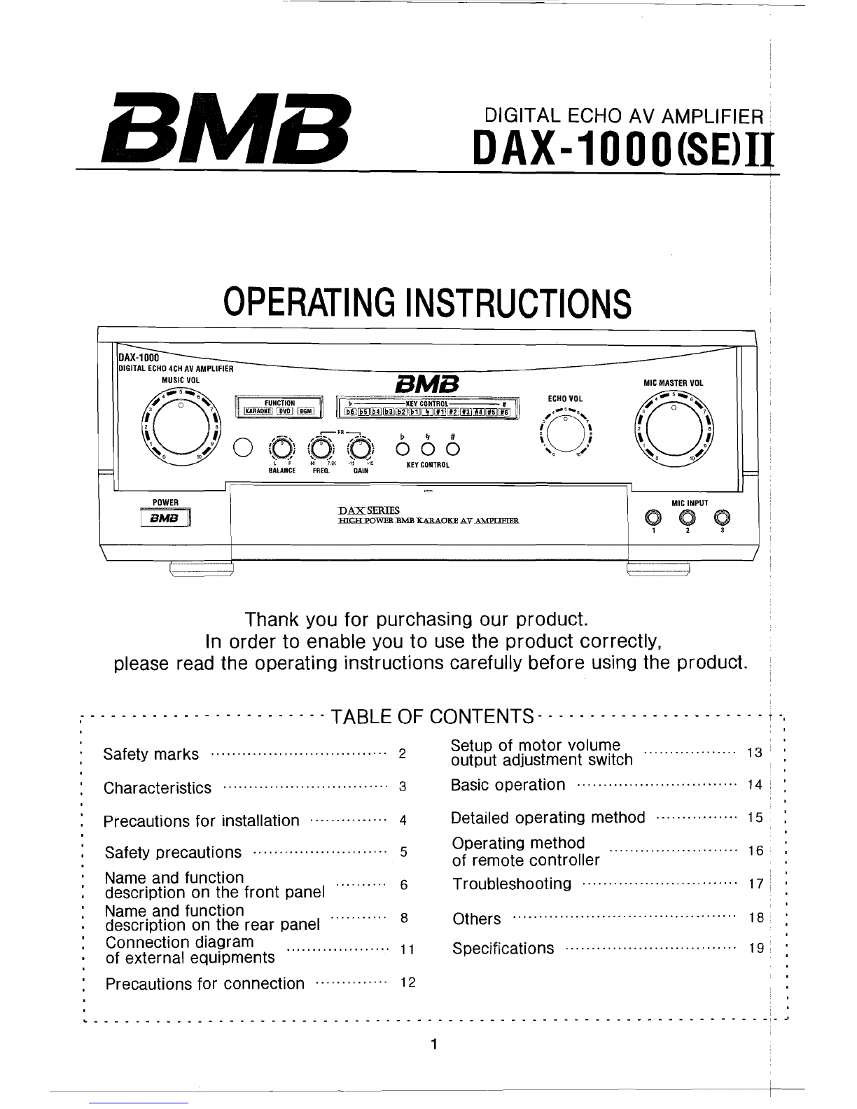
DIGITAL ECHO AV AMPLIFIER.
DAX-1000(SElII
OPERATING
INSTRUCTIONS
MIC
INPUT
o 0
1 2
DAXSERIES
EIGH:POWEB.:BMB
XAllAOKE
AV
I\MPfll!lHR
POWER
I
BMB
~
BMB
,...--FR
---,
__;,
,\
/D-~"'\
/0-"-\
b " #
\0i i' ; i ;
000
'. .'
'..'
'.~'
L " 80 7,5K -12
'1~
KEY
CONTROL
BALANCE
FREQ.
GAIN
Thank you for purchasing our product.
In order to enable you to use the product correctly,
please read the operating instructions carefully before using the product.
....
- - - - - - TABLE OF CONTENTS - - - - - - - - . - i .,
Safety marks
Characteristics
Precautions for installation
Safety precautions
Name and functio
description on the front panel
Name and functio
description on the rear panel
Connection diagram
,
Setup of
motor
volume 13
2 output adjustment switch
3 Basic operation 14
4 Detailed operating method 15
Operating method 16
5 of remote controller
Troubleshooting 17
6 Others 18
8
11 Specifications 19
....................
of external equiprnents
Precautions for connection 12
II._-_
..
~
..
_----_
..
----_
....
_---_
..
----"------""-------------"
..
------------~
1

SAFETY MARKS
In order to enable the user to use the product correctly and
conveniently and prevent any body injury and property loss
in using, please read the following precautions carefully
before using the product.
The safety marks are defined as follows:
Please read the following precautions carefully.
WARNING
It might cause serious body injury
and even death accident if it's
used in breach of the instructions.
ATTENTION
It might cause serious body injury
or product damage if it's used in
breach of the mark instructions.
e The sign at the left means the content of the noxious and
hazardous substance is lower than the limit of SJ/T 11363-2(j)06
I"
corrUga:~ed
I
\~
" " BAG FOR I " BAG FOR
I
C~
board
C~
~~~~~~L
C~
MACHINE
I
C~
PARTS '
~KING
BOX Clapboard PS HDPE L LDPEI
-T------'
2
1-
---------------+--1
~

CHARACTERISTICS
Major characteristics of this KARAOKE AV AMPLIFIER are as follows.
Powerful Output Force of Amplifier
The master amplifier comprising the big power transistors features
excellent maximum output power and
I.M.D
to get ideal recovery effect
and provide the perfect hearing effect.
Application of STEREO
ECHO
The function of stereo echo makes the user feels he/she is at the site
and the better accompaniment effect will be produced.
Built-in Feedback Reducer
The built-in feedback reducer could ettectively solve the problem of
microphone howling in various environments and prevent howling.
Perfect
Built-in
Protective Circuit
When the overload current in the amplifier is too big or too hot and
the unit of loudspeaker has short circuit, the built-in protective circuit
shall be activated automatically to effectively protect the device and
loudspeaker.
Sound Quality Improvement Design
In order to recover the sound source signal cerfectly, by improving
the noise ratio of signal band to shorten the transfer distance of
signal, decrease the intermodulation distortion of left/right track
and reduce the interruption of signals as well as reduce the effect of
power to the signal source to further improve the output sound quality.
Convenient Volume Adjustment Function
It could adjust the volume of microhpone independently and adjust the
master volume and the tracks of loudspeaker respectively.
Auto Input Sound Source Selection
It could detect the external equipment automatically and select the sound
source of input automatically.
3

PRECAUTIONS FOR INSTALLATION
Do not install the product at the following places:
- Bad ventilation or airtight environments
- Near the heating equipments or under the direct rays of the sun.
- Unstable fields
- Damp or dusty fields.
Right installation
The
product
will
produce
some
heat
in working, so it
should
be installed
at the place
where
has
good ventilation.
Please
keep the upper
side
of device
10cm
or more
away
from the
wall,
and
Scm
or more for the two
sides;
10cm
or more for the rear
side.
IS-l0cm I
U
~
~~~~ij~
~~~
~~ ~~
~~~~~~~~~
~~~~ij~~~~~~~~
~~m
~~~~~~~~~~~~
~~~~~~~m~~~~II~uIIIIIW~~~III@III~~IWmlllll~IIII~III!~iWiiIWIIIW
l~w,,~r
~
~~mlll~ulllllm~~~~II~
I1I1
~11[i~
[IIWlllmu~lliIIW[I~ullll~~llllllullll~
IIII
~
@ ® n
Before
connecting
Precautions
When connecting, please pull off the power cable from the power
socket and then reconnect, the names of terminals could be different
with the device.
At that moment, please refer to the instructions to connect correctly.
It should use these loudspeakers that impedance is higher than 6
Q.
If it's connected wrongly, it might damage the device and produce noise.
After being installed, if the connection cable is mixed with other cables,
or it's too close to other electric products, noise might be produced.
The product has two power output ways including coupled power output
and uncoupled power output; please select the right terminal in using.
Output power of AC output terminal
The output power of used audio equipment couldn't be exceed the
maximum output power. The power output terminal (AC outlet) could be
used for the connection of audio equipment only. Do not use together with
other electronic products (such as electric heater and other electric products
whose powers are over than the nominal power).
4

SAFETY PRECAUTIONS
Do use the rated AC power
-The
product should use 230V/50Hz power.
*If the
voltage
is
over
high, it might cause
fire or
electric
shock
and
other
accidents.
Do
not
connect
the
AC
power
to
the
amplifier
in
the
touowinscondltlons:
-When connecting instruments to the amplifier.
-When it's not used for a long time.
-When cleaning the product or making
maintenance.
*It
might cause fire, electric shock or
other accidents.
Do not dismantle or rebuild the housing
by yourself.
* It might cause fire, electric
shock
or
other
accidents. If
it's
needed to
repair
or
check,
please
contact
our
agent or service
center.
Do not connect these equlprnents that use
the bigger output power.
-.
!
'
~
.•
I
~~
* It might cause fire. electric shock or
other accidents.
Do not let any external object
or water get into the amplifier.
000
=
If the
external
object
or
water
gets
into
the amplifier, it might cause fire, electric
shock
or
other
accidents. In that case.
please
turn
off
the
power
immediately
and pull
off
the
power
plug
and
contact
our
service
center
as
soon
as possible.
--------_.
__
._._._---
Do not damage the power cable.
-Do
not
bend or pull the cable by force.
-Do
not
place heavy object on the cable.
-Do
not
change the cable by yourself.
-Do
not fix the cable by bolts.
-Do
not
place the cable near the warming
stove or air heater or other heating
ecuiprnents.
*If
the cable is damaged, it might cause fire,
electric
shock
or other accidents, please
contact our agent or service center quickly.
If the device gives
off
strange smell,
smoke or abnormal sound.
It might cause fire. electric shock or other
accidents, at this moment, please turn off
the power immediately and pull off the power
plug,
and contact our agent or service center
quickly.
5
- - -
-
--
-
--
NAME AND FUNCTION DESCRIPTION ON FRONT PANEL
CD
@GM) ®
®~®@
@
D~
DIGITAL
ECHO
4CH
~
I
AMPLIFIEF
-
MUSIC
I lL
~I~
{[~}
\ I
1 , ,, , \•
0
~
'f)' t1
to
40
4D
\ i \ i \ ;
-c .- -e ."
~o
,,~
I. 10
7.51<
-u
"
.-
.Il
KEY
CONTROL
BALANCE
FREQ.
GAIN
=
BALANCE
BGM MUSiC
TONE
Sl~~~O
l4~
POWER
~~I~~
~lol@:
1 1
~4
'I~
-10 +\!
-I'
+'1
..,~
-:,,, • _ I"
1'.
0"'..
SP1·2
BASS
MID
TREBLE
REPT
H (
- - -
BJ
~.
~
-KEY
~
DNTRD
:Hn
~
rulllJ[ij]~iHJ
III
#
---
~"=
r
FU'
;T10N
]
~
~
~
~I
r--f'R-
.,
ECHJl;OI
Mit
TONE
Mit
VOL
ECHO
MIC
INPUT
~I~
i~:~I@:~~
0 0 0
... 1'0 ..
;~.
{,.
-I~
-:i.
-1'0'
-;;, ...
1'.
...
~
0"
fo
",a_
..
DELAY
BASS
MID
TREBLE
1/A 2/B
3------J
1 ,
\ \
®
@@@@@@@@@@@@@@@
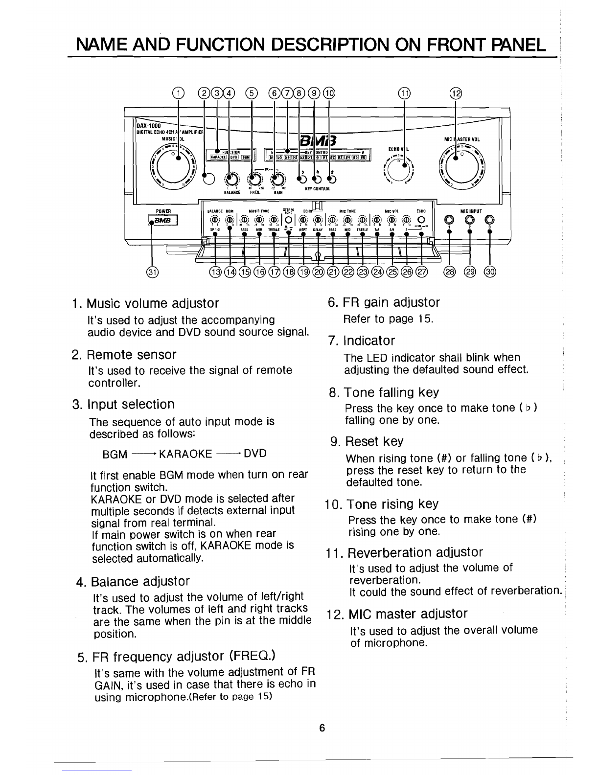
1. Music volume adjustor
It's used to adjust the accompanying
audio device and DVD sound source signal.
2. Remote sensor
It's used to receive the signal of remote
controller.
3. Input selection
The sequence of auto input mode is
described as follows:
BGM - KARAOKE - DVD
It first enable BGM mode when turn on rear
function switch.
KARAOKE or DVD mode is selected after
multiple seconds if detects external input
signal from real terminal.
If main power switch is on when rear
function switch is off. KARAOKE mode is
selected automatically.
4. Balance adjustor
It's used to adjust the volume of left/right
track. The volumes of left and right tracks
are the same when the pin is at the middle
position.
5. FR frequency adjustor (FREQJ
It's same with the volume adjustment of FR
GAIN.
it's
used in case that there is echo in
using microphone.(Reter to
page
15)
MICI~L
ECHO
VL
lG'~
\,
"'-
,I \
l
1
'\
•
i
'0
10~
r2
~o
,,~
F=
0
3
@® ®
6. FR gain adjustor
Refer to page 15.
7. Indicator
The LED indicator shall blink when
adjusting the defaulted sound effect.
8. Tone falling key
Press the key once to make
tone
( D)
falling
one
by one.
9. Reset key
When rising
tone
(#)
or falling
tone
( D),
press the reset key to return to the
defaulted tone.
10. Tone rising key
Press the key once to make
tone
(#)
rising one by one.
11. Reverberation adjustor
It's used to adjust the volume of
reverberation.
It could the sound effect of reverberation.
12. MIC master adjustor
It's used to adjust the overall volume
of microphone.
6
NAME AND FUNCTION DESCRIPTION ON FRONT
PANEL
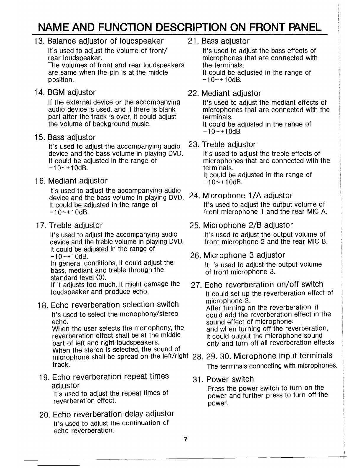
13. Balance adjustor of loudspeaker 21.
Bass
adjustor
It's used to adjust the volume of
front!
It's used to adjust the bass effects of
rear loudspeaker. microphones that are connected with
The volumes of front and rear loudspeakers the terminals.
are same when the pin is at the middle It could be adjusted in the range of
position.
-10-+10dB.
14.
BGM
adjustor 22. Mediant adjustor
If tile external device or the accompanying It's used to adjust the mediant effects of
audio device is
used,
and if there is blank microphones that are connected with the
part after the track is over, it could adjust terminals.
the volume of background music. It could be adjusted in the range of
-10-+10dB.
15. Bass adjustor
It's used to adjust the accompanying audio 23. Treble adjustor
device and the bass volume in playing
DVD.
It's used to adjust the treble effects of
It could be adjusted in the range of microphones that are connected with the
-10-+10dS.
terminals.
It could be adjusted in the range of
16. Mediant adjustor
-10-+10dB.
It's used to adjust the accompanying audio
device and the bass volume in playing
DVD.
24. Microphone
1/
A adjustor
It could be adjusted in the range of It's used to adjust the output volume of
-10-+10dS.
front microphone 1 and the rear MIC A.
17. Treble adjustor 25. Microphone 2/B adjustor
It's
used
to adjustthe accompanying audio It's used to adjust the output volume of
device and the treble volume in playing
DVD.
front microphone 2 and the rear MIC S.
It could be adjusted in the range of
-10-+10dB.
26. Microphone 3 adjustor
In general conditions, it could adjust the
It's
used to adjust the output volume
bass,
mediant and treble through the of front microphone 3.
standard level
(0).
If it adjusts too much, it might damage the 27. Echo reverberation
on/off
switch
loudspeaker and produce echo. It could set up the reverberation effect of
microphone 3.
18. Echo reverberation selection switch After turning on the reverberation, it
It's used to select the monophony/stereo could add the reverberation effect in the
echo. sound effect of microphone:
When the user selects the monophony, the and when turning off the reverberation,
reverberation effect shall be at the middle it could output the microphone sound
part of left and right loudspeakers. only and turn off all reverberation effects.
When the stereo is selected, the sound of
microphone shall be spread on the left/right 28. 29. 30. Microphone input terminals
track. The terminals connecting with microphones.
19. Echo reverberation repeat times 31. Power switch
adjustor Press the power switch to turn on the
It's used to adjust the repeat times of power and further press to turn off the
reverberation effect. power.
20. Echo reverberation delay adjustor
It's used to adjust the continuation of
echo reverberation. 7
-----
NAME
AND
FUNCTION
DESCRIPTION
ON
THE
REAR
PANEL
I
!
I
I
I
KARAOKE
tWO
I 11
..
I. .. OUT
lILF!Ti~lJ;r~I:;'T'-"-~
-'
-
-Jo-_
@
@@@
l~=
@@
@'I@
@@
@
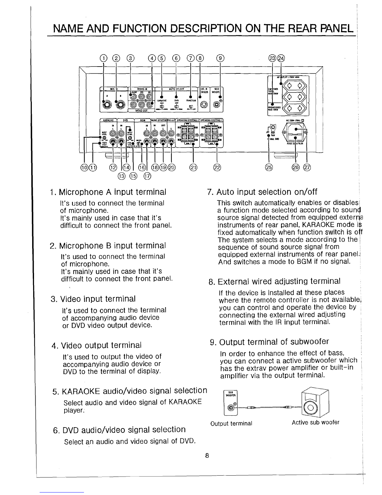
1. Microphone A input terminal
It's used to connect the terminal
of microphone.
It's mainly used in case that
it's
difficult to connect the front panel.
2. Microphone B input terminal
It's used to connect the terminal
of microphone.
It's mainly used in case that
it's
difficult to connect the front panel.
3. Video input terminal
It's used to connect the terminal
of accompanying audio device
or DVD video output device.
4. Video output terminal
It's used to output the video of
accompanying audio device or
DVD to the terminal of display.
5.
KARAOKE
audio/video signal selection
Select audio and video signal of KARAOKE
player.
6.
DVD
audio/video signal selection
Select an audio and video signal of DVD.
7. Auto input selection
on/off
This switch automatically enables or disables!
a function mode selected according to sound
source signal detected from equipped exterrja
instruments of rear panel, KARAOKE rnode is
fixed automatically when function switch is
oft
The system selects a mode according to the i
sequence of sound source signal from •
equipped external instruments of rear panel.
And switches a mode to 8GM if no signal.
8. External wired adjusting terminal
If the device is installed at these places
where the remote controller is not available;
you can control and operate the device by
connecting the external wired adjusting
terminal with the IR input terminal.
9. Output terminal of subwoofer
In order to enhance the effect of bass,
you can connect a active subwoofer which
has the extrav power amplifier or
built-in
amplifier via the output terminal.
Output terminal Active sub woofer
8

NAME
AND
FUNCTION
DESCRIPTION
ON
THE
REAR
mNEL
G)®@
0®
®
00
®
@@
.....
_----------
---~
._------------_/
AC nET/230V50Hz
SWI
CtiED
~
~'1~ow
~
>-:~
UNSWITCHEO
~
MAX100W
'\:
::/
At
2JI1V-/5(lHz!IJ
{a
~
I
r~',-~
--
--1
I-I-I-j-I
'·':~i~·i
--
=,=-:~:.~-
~
~
~
~LI
KARAOKE
OVO
FU'CTIO,
EI7
_
EI7
D C
~~I}
~
~~
@ @
VID£O
OUT AlIIllO .,,0£0 AUDIO VIMO
O~
OFF
IN IN IN IN
DUT
l L L L l L
lWil
~~
l'I:'J
~~~~
ILF+T~~~~TrT--
--
---
@@ ©
t~
L6t~@®
@@
@
10 KARAOKE input level adjustor
When the KARAOKE input signal level
is too big or too small, it could adjust
through KARAOKE input level adjustor.
11. KARAOKE sensitivity switch
Set the sensitivity at which KARAOKE
audio input level is detected and switched
automatically.
12. KARAOKE input terminal
It's used to connect the output terminal
of accompanying audio device
(KARAOKE device).
13.
DVD
input terminal
It's used to connect the output terminal
of
DVD.
14.
DVD
input level adjustor
When the
DVD
input signal level
is too big or too small, it could adjust
through
DVD
input level adjustor.
15.
DVD
sensitivity switch
Set the sensitivity at which
DVD
audio
input level is detected and switched
automatically.
16.
BGM
mono/stereo select switch
Select the BGM signal input mode between
mono and stereo through the switch.
17. BGM input terminal
It's used to connect the output terminal
of BGM (back ground music) device.
18. Effector input terminal
In order to enhance the music effect
of accompanying audio device or
DVD,
it's used to connect the input terminal of
sound effect adjustor.
19. Effector ouout terminal
In order to enhance the music effect
of accompanying audio device or
DVD,
it's used to connect the input terminal of
sound effect adjustor.
20.
Pre-output
terminal
In order to enhance the output of
loudspeaker, when using the external
amplifier, it's to connect the
pre-output
terminal on the main device and input
terminal of the external amplifier.
9

--
NAME
AND
FUNCTION
DESCRIPTION
ON
THE
REAR
PANEL
CD
® ®
00
®
0®
®
--==-t---
---!.!£.I!-
vIDeo
IN
-j
~~I:
l=-l;~j
KARAOKE
DVD
FUNCTiON
EB
· .'
~U
@0
~J~~
."
,'"
, §
~
,".,,~".ro
~.~"."
..
512~
VIDEO
OUT
-----I-----~
......
__
-._-_
-_.._-
-_
..
_---_
.
_~~_
~_
~--~--
AC
UTLET
I 230V50Hz
UNSWITCHED
~
MAX1110W
~
~
•.•
i
•••••
~
':-~bll
__
~_
FUSE25~'~
-l
@@ @ @ @ @@@ @
@@
@
*Note:
When it's needed to connect the
external amplifier, please turn off the
power and external amplltler first and
confirm whether the volume adjustor is
at the smallest status, and then connect.
Too big output level might damagethe
product and the loudspeaker.
21. Loudspeaker terminal 2
It's used to connect the terminal of
loudspeaker 2.
Please refer to page 9 for the connection.
22. Loudspeaker terminal 1
It's used to connect the terminal of
loudspeaker 1.
Please refer to page 9 for the connection.
23. Power output terminal
(uncoupled switch)
When turn
on/off
the power, the power
is always in output state. The max. rated
power of the output terminal is 100W.
Do not use the bigger rate devices.
24. Power output terminal
(coupled switch)
When turn on/off the power, the power
shall be turned on/off.
@
@@
The max. rated power of the output
terminal is 200W.
Do not use the bigger rate devices.
25. Grounding terminal
It's used to connect the external device.
The terminal is used to prevent the
noise and electric shock when using
the microphone. Do make grounding
protection in using.
If the place is wet or it's not good for
grounding connection, it might cause
fault, electric shock, fire or other
accidents.
26. Fuse
Open the fuse cover, you will
see the fuse.
Please use the same specification
product when replacing the
'fuse.
27. AC input
The product uses 230V/50Hz AC
voltage, please insert the power cable
into the socket after connecting the
terminal.
* Precautions
Please use the attached power cable
when connecting. It might cause fire
or damage if other kinds of cables
are used.
10
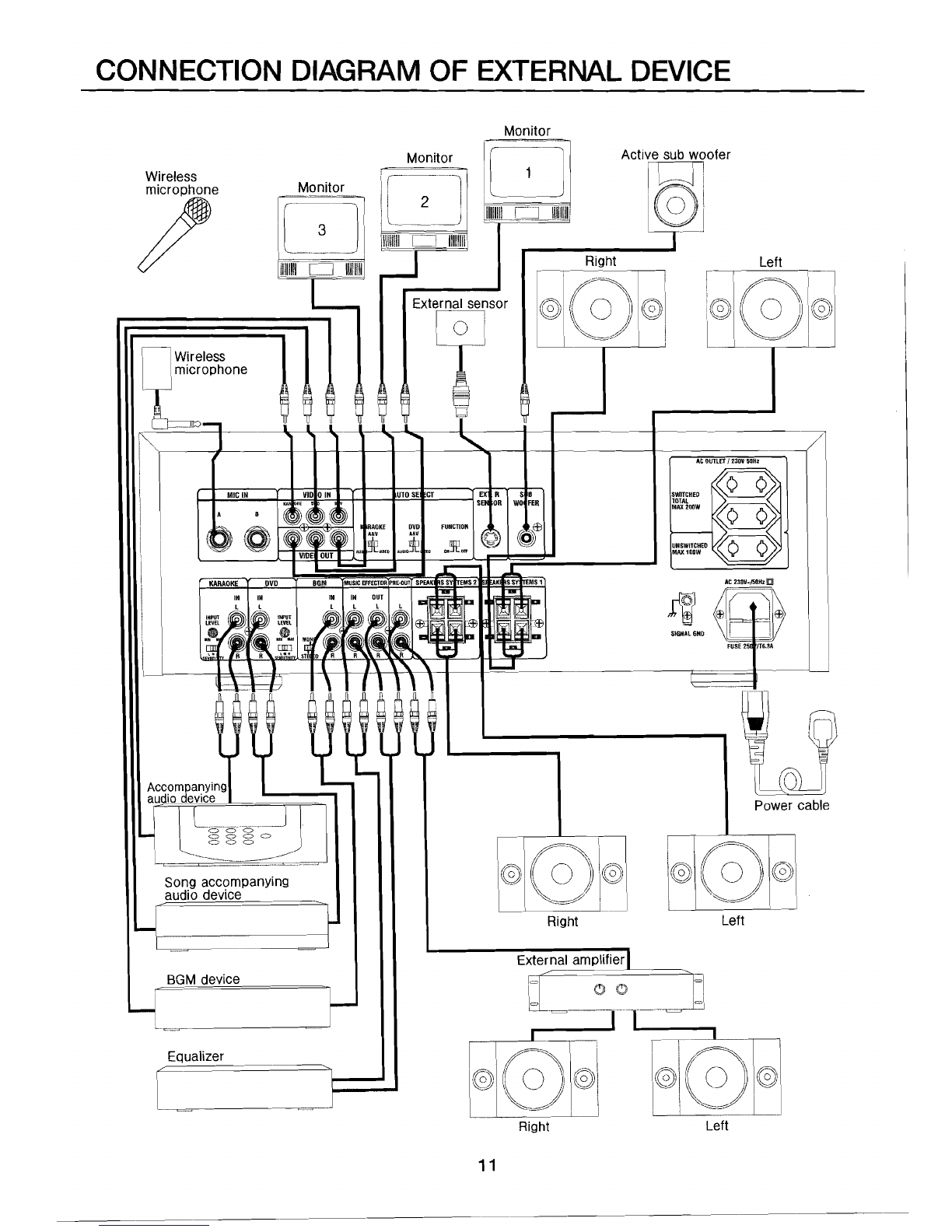
CONNECTION DIAGRAM OF EXTERNAL DEVICE
Monitor
Active sub woofer
Monitor
[--
..
_-
~
--1····-~~l
II
Wireless
\F-
-----l!
'I _
microphone Monitor
Iii
Its)
I
/
Ii
2 !IIIIIIIIIOUlIIIIIJ
S B
WO
FER
EfJ
9!@
.....
'-
1[-=-1
I
~--:~---=-
.
I~~j
=
__
I
~~1II11
0
111111111
II J Right Left
11111111 11111111
[:.:J
External sensor
[t
II
TImicrophone
Wireless ,
LL._Jlo-,
!"',
I At
OUTLET
/230V 50Hz
(I
SWITCHED
~
MICIN
VID
OIM
UTOSE
CT
EX
R
KA KE D
SE~
OR
~'l.lAIODW
~
~
RAOK.
E DVD
FUNCTION
~
A •
~rtt
~
OQ~-
~ ~
~
UH$WITCHED
~
V1DE
OUT.
AU
;/IOEfJ
l\JOlll eu Q. MI'
MAX1QOW
~
At
230Vw/SllHz
IQI
FUSE25 jT6.3A
, \ 1 I
1\
"
~
L-.J
'--
-
Ul)
I~
d
~
;
I;
~
,,--~===.
-,
I
\!&
V
11
(QLI.
Accompanvms
~~_
.........
Power cable
Left
L.~
-----~~
...
B8M device
r
Equalizer
I
......
_---------
--------.
Song accompanying
audio device
audio device -
~I----I
-----------jl-
Left
11
CONNECTION
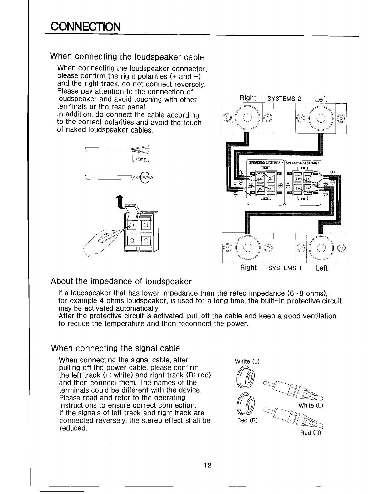
When connecting the loudspeaker cable
When connecting the loudspeaker connector,
please confirm the right polarities (+ and
-)
and the right track, do not connect reversely.
Please
pay attention to the connection of
loudspeaker and avoid touching with other
terminals or the rear panel.
In addition, do connect the cable according
to the correct polarities and avoid the touch
of naked loudspeaker cables.
\~--
__
--'~o:=~
lJjm'!'~
1;f(O)~
LC~u
Right SYSTEMS 1 Left
About the impedance of loudspeaker
If a loudspeaker that has lower impedance than the rated impedance
(6-8
ohms),
for example 4 ohms loudspeaker, is used for a long time, the built-in protective circuit
may be activated automatically.
After the protective circuit is activated, pull off the cable and keep a good ventilation
to reduce the temperature and then reconnect the power.
When connecting the signal cable
When connecting the signal cable, after
pulling off the power cable, please confirm
the left track (L: white) and right track (R: red)
and then connect them. The names of the
terminals could be different with the device.
Please read and refer to the operating
instructions to ensure correct connection.
If the signals of left track and right track are
connected reversely, the stereo effect shall be
reduced.
12
1 _
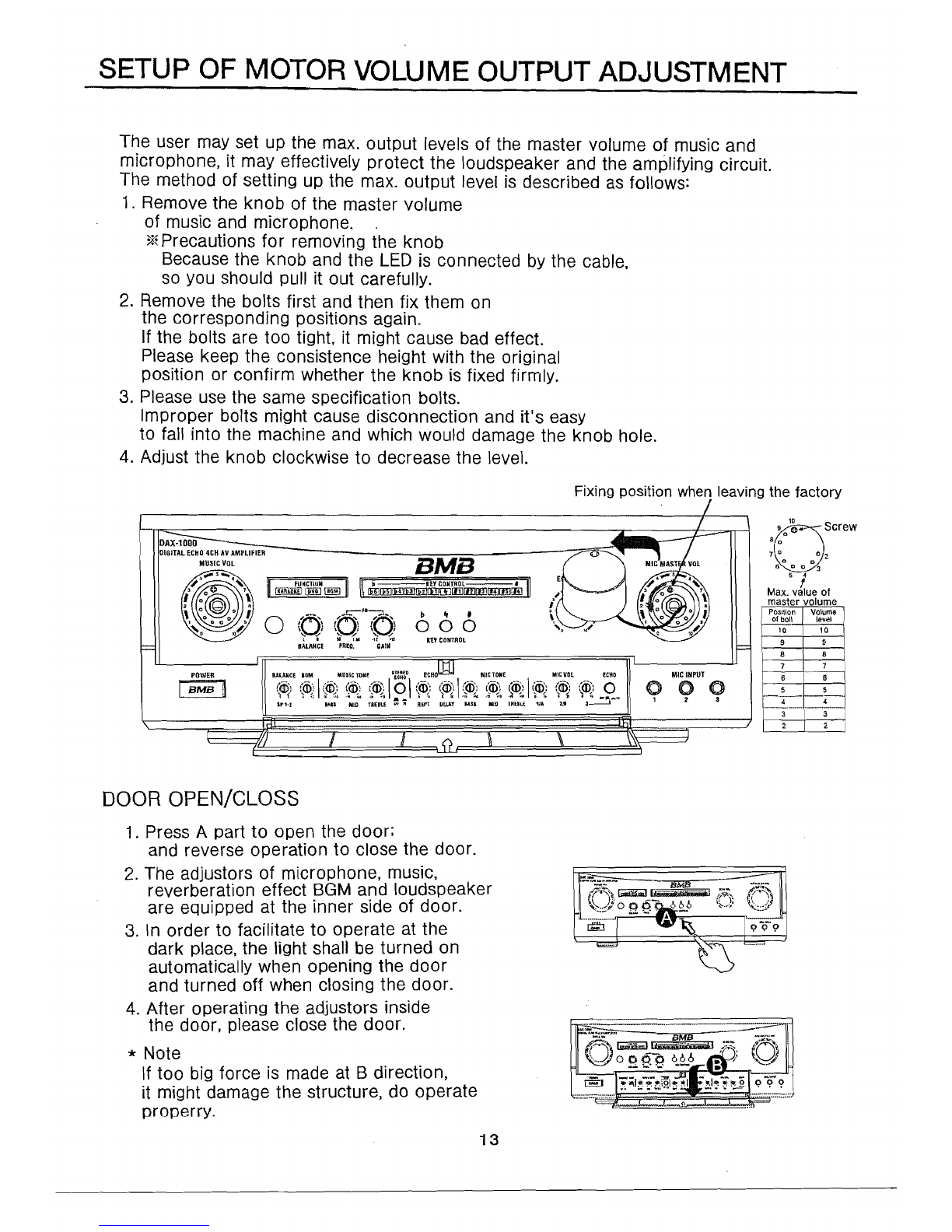
SETUP OF MOTOR VOLUME OUTPUT ADJUSTMENT
The user may set up the max. output levels of the master volume of music and
microphone, it may effectively protect the loudspeaker and the amplifying circuit.
The method of setting up the max. output level is described as follows:
1. Remove the
knob
of the master volume
of music and microphone.
*Precautions
for
removing the knob
Because the knob and the
LED
is connected by the cable,
so you should pull it out carefully.
2. Remove the bolts first and then fix them on
the corresponding positions again.
If the bolts are too tight, it might cause bad effect.
Please keep the consistence height with the original
position or confirm whether the knob is fixed firmly.
3. Please use the same specification bolts.
Improper bolts might cause disconnection and it's easy
to fall into the machine and which would damage the knob hole.
4. Adjust the knob clockwise to decrease the level.
Fixing position when leaving the factory
10
9 0 (} Screw
a 0
1\°n 0 2.
.z 0
Ii
5~~
3
f
Max. value of
master volume
Position Volume
of boll level
10 10
9 9
8 8
7 7
6 8
5 5
4
_.~--
3 3
2 2
BMB
POWER
I
BMB
~
DOOR OPEN/CLOSS
1. Press A part to open the door;
and reverse operation to close the door.
2. The adjustors of microphone, music,
reverberation effect
BGM
and loudspeaker
are equipped at the inner side of door.
3. In order to facilitate to operate at the
dark place, the light shall be turned on
automatically when opening the door
and turned off when closing the door.
4. After operating the adjustors inside
the door, please close the door.
* Note
If too big force is made at B direction,
it might damage the structure, do operate
properry.
13
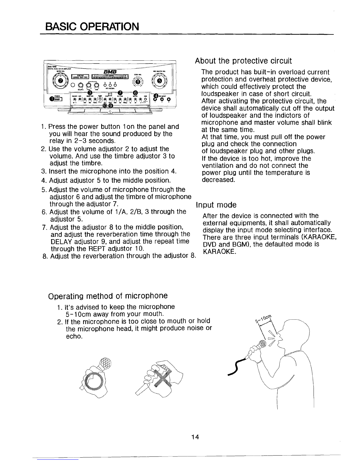
BASIC
OPERATION
1. Press the power button 1on the panel and
you will hear tile sound produced by the
relay in
2-3
seconds.
2. Use the volume adjustor 2 to adjust tile
volume. And use the timbre adjustor 3 to
adjust the timbre.
3. Insert the microphone into the position 4.
4. Adjust adjustor 5 to the middle position.
5. Adjust the volume of microphone through the
adjustor 6 and adjust the timbre of microphone
through the adjustor 7.
6. Adjust the volume of
1/
A, 2/B, 3 through the
adjustor 5.
7. Adjust the adjustor 8 to the middle position,
and adjust the reverberation time through.the
DELAYadjustor 9, and adjust the repeat time
through the
REPT
adjustor 10. .
About the protective circuit
The product has built-in overload current
protection and overheat protective device,
which could effectively protect the
loudspeaker in case of short circuit.
After activating the protective circuit, the
device shall automatically cut off the output
of loudspeaker and the indictors of
microphone and master volume shall blink
at the same time.
At that time, you must pull off the power
plug and check the connection
of loudspeaker plug and other plugs.
If the device is too hot, improve the
ventilation and do not connect the
power plug until the temperature is
decreased.
Input mode
After the device is connected with the
external equloments. it shall automatically
display the input mode selecting interface.
There are three input terminals (KARAOKE,
DVD
and BGM),the defaulted mode is
KARAOKE.
8. Adjust the reverberation through the adjustor 8.
Operating method of microphone
1. It's advised to keep the microphone
5-10cm
away from your mouth.
2. If the microphone is too close to mouth or.hold
the microphone head, it might produce noise or
echo.
14

DETAILED
OPERATING
METHOD
Operating method of key controller
-D
~
KEY
CONTROL
--=
#
I]
~_~l~~~_~Q;J~~_~~I~
...
I
D 'I #
~OO
GONTROL
b 1. Press the key once to decrease the tone one level by level.
It could adjust in the range of b 1- b 6, and b 6 is the smallest tone.
2. After the music is over, it shall return to the defaulted sound
effect in 4 seconds.
[Q}]-crn-[QID-[Q!J-~-[I§]
q In rising/falling the tone, press reset key to return to the defaulted tone.
# 1. Press the key once to increase the tone one level by level.
It could adjust in tile range of #1
-#6,
and #6 is the highest tone.
2. After the music is over, it shall return to the defaulted sound
effect in 4 seconds.
[IjJ-[Rj-~-[ll]-~-[H]
..
It might cause fault or wrong operation if pressing down the two or
more keys at the same time.
Operating method of FR
1. Rotate the FR
GAIN
knob and adjust to "0".
~:J'~\
FR7(/!&D't\
'U"~
,
';.'
80 -12
'_.'
7.5K
+12
FREQ.
GAIN
2. Adjust the volume and timbre of accompanying audio device.
3. Open the microphone, if there is echo after testing;
adjust the knob of FR to 12 o'clock direction.
17i~/D'~"':\
\ " i \ Iii
'
..
' '.
--~
80
7.5K
-12
+12
FREQ.
GAIN
4. Rotate leftward (80Hz) or rightward (7.5KHz) slowly till no echo is produced.
,--FR~
((1)
(r'~')
~./
..
/
80
7.5K
-12
+12
FREQ.
GAIN
5. After the echo is disappeared, 'fixthe volume of
FREQ.,
and then rotate the
knob of FR GAIN leftward
(0
direction) till no echo is produced any more.
,--
FR
----.::'\.
(~.~~)
(n.~).
u u
80'
·7.5K
-Ii
'+12
FREQ.
GAIN
15

OPERATION OF REMOTE CONTROLLER
The attached remote controller is applicable for DAR series products.
Operating range
~,,~
~lllItAlrt.ltllJCIlAr"'MI1.IJ1f.
-====
_lPIUll.Y1ll
:~~~~
5MB
ICl1Q~aL
tJ'"
1""\'-'"
I I . ,n,..." • I
l;;~
{!
,\
~
am
!IDiil!IDmWWt1JrrmtIfPi!'!
{~~:)"
,~,
'~R06\o'"
\'''''
..
~-:/
~.L
A
~
l'
'
,'"
1 0 0 0
~_
....
~:s
.~,i"
~
..
.....:..
......
InCDIIl1lO~
~<:::".Y'
____
A F
.. -
_....
_..
_-
....
__
.__.-
-
,"
-
"
!"Own
I
1I1t_l'II'
DAX
......
HlCMI'OWM_IItIt.AMJIUIA"~
IBNii!t
<;>
<;> <;>
I\
I
--.
~
"~I£
"
\
I I \
I I \
I I \
II~~\
The available distance is 7 meters with the
angle of
+/-30
degrees.
I
-F~~-7m
BMB
• I •
===
9~
0<::;:10
fDIO MlIhG we
Precautions
The effect is not good if the remote controller is under
the strong sunshine.
Please
check whether there is any other object between
the controller and the sensor.
It might cause wrong operation if you press the functional
keys of remote controller and device at the same time.
Method of replacing the battery
il~
~I
Precautions
1. If the remote controller is not so sensitive, please replace dry batteries with new ones.
2. If it's not used for a long time, please take out the dry batteries and keep them at the
place out of reach of children.
3. Do not charge or heat the dry battery, it might cause fire, blast or other accidents.
16

TROUBLESHOOTING
Please refer to the following steps if the product has any trouble.
And if it's unable to be solved after checking, please contact our
agent or service center.
Troubles
Causes
Solutions
The AC power cord is not connected Connect the power cord to
The amplifier has to the amplifier. the amplifier.
no power Replace the fuse.
The fuse is fired.
The speaker cable is not connected Reconnect the cable to the
to the loudspeaker. loudspeaker.
Has no sound Adjust the volume level.
The volume level is too small.
The volume is too small. Adjust the volume.
couldn't hear the The connection of microphone is
not good. Check the connection of
microphone.
sound of music or The connection with external Check the connection port.
microphone equipment is not good.
The external equipment has troubles. Check and confirm whether the
external equipment is working
normally.
The background music
is normal but the sound The volume level of microphone is
too low. Adjust the volume level of
microphone.
of microphone is too The master volume level of Adjust the master volume level of
small
.
__
._
.........
_~-_
....
_._-----_._._-_.
__
....._ microphone is too low.
.....
1--------
......
--
.......
------_
..
_--
.....
__
..........
microphone.
The remote controller No batteries or the battery
electricity is not enough. Replace it with the new batteries.
is not working Take away the objects between
the controller and the sensor. Take away the objects between
the controller and the sensor.
Check
a loudspeaker's connection.
The loudspeaker has short circuit.
on/off
frequently
The relay is turned The unit of loudspeaker is not good. Check the unit of loudspeaker.
.....
__
.
__
.._._---_..
_--_
....
__
._---_
......--_._...
__
.......
.....
_--_
..
_------_.-
.._....
_---------
_.~-----_.
----_
..
~------_
...
_._
....
__
._-_..
_-_
..
-------
The distance between the microphone Adjust the distance between the
and loudspeaker is too short. microphone and loudspeaker.
Rotate the loudspeaker towards
The sound of loudspeaker is mixed
with the sound of microphone.
The echo is too big outside.
The treble area is too high. Adjust the treble properly.
_._
......_
..........
_.
__
._
....-..
_----_._---_
.......
_.-._._
.....
_......_--_....
_._._._
..
__
...-.__......_..._...
-._-
.
-_
.._ ....._
........
Adjust the volume of
ECHO.
No
ECHO
effect in case The master volume of
ECHO
is "0".
of microphone output Adjust the master volume.
"When
product have some problem or broken, please don't repair in repairing store
with liberty, should consult information from our after-sales center or our distributor.
- Address, name and phone number
- Product name, model and purchasing date
-Faults (detailed description)
- Expected treatment time
17
OTHERS
Maintenance
If the surface of product is dirty, please use the clean cloth to clean the
surface, if it's too dirty, you should use the soft cloth and proper amount
of detergent to clean as per the proportion of 1
:4-1:5
(detergent and water)
After cleaning with the wet cloth, please use the dry and clean
cloth to wipe again. Do not use the volatile chemical agents such as benzene.
The volatile chemical agents could damage the painting on the surface.
Operating
environment
1. Avoid to affect the rest of neighbors when using
KARAOKE
at home
and note the time and place.
2. Prevent the sound affect others, it's advised to adopt the sound
separation measures when using the product at home.
3. Turn down the volume at night and it's better if not using the product
at night for small sound would also affect the rest of others.
Property
right
The broadcast, sound source and
CD
are protected by the intellectual
property right in accordance with the law of intellectual property protection.
It's forbidden to use as commercial or transfer to others.
Product
materials
The product is made from the nontoxic and hurtles materials in
accordance with the relative safety rules and regulations.
18

SPECI
FICATIONS
Amplifier Accessories
Rated
power
1
60W
x 4 / 8.Q Operating Instructions , 1
Remote Controller 1
Input sensitivity/impedance Dry Battery 2
KARAOKE
200mV
/ 22kQ Power Cable 1
DVD
300mV
/ 22kQ
BGM ,
300mV
/ 22kQ
MIC
17mV
/
3.3kQ
Output power
MUSIC EFFECTOR
OUT·····
190
mV / 1
kQ
SUB WOOFER (150Hz) 5.8V / 1
kQ
PRE
-OUT
3.6V / 1
kQ
VIDEO OUT 1
VP-
p/75
Q
Timbre adjustment of music
BASS ± 1OdB(
100Hz}
MID ±
10dB(2KHz}
TREBLE ± 1OdB(
10KHz}
Timbre adjustment of microphone
BASS ± 1OdB(
100Hz}
MID ±
10dB(2KHz}
TREBLE ± 1OdB(10KHz}
Power supply
Power supply
230VAC,
50Hz
Power
800W
Power output terminal .. Coupled
switch>
2
(Max. 200W)
r-i -r-rr-
IIMII
r
-,
==
= === = = ==
-r:=J 1 J
F"""""::.
:::'"",
..
BMB (0
"'
..
I~_i
~
(e~l
0
666
,
,-
e
8'~:
0 -
u""
-..-~A"
....
__
......
~
I I
«;l
·cf
«;l
I
~
'=
251mm
Uncoupled switchx 1
1--
----'l£\!.!ill!L
--i
(Max. 100W)
Dimensions
420
x
159
x
415
rnrn
(Wx
Hx D)
Weight
17.4Kg
420mm
E
.Ii
..-
E E
E E
<T> <T>
0
-'"
-
*The specifications shall be subject change without any further notice.
19

BMB
BMB
International
Corp.
http://www.bmb.com
Other BMB Amplifier manuals
II User manual")


Popular Amplifier manuals by other brands


Taramps Electronics
Taramps Electronics DS440X4 instruction manual

Applied Research and Technology
Applied Research and Technology HP-1 quick start guide

NuWaves
NuWaves NUPOWER 13G05A user manual

Hogtunes
Hogtunes Quadcast QC475-RM installation manual

Clearaudio
Clearaudio Absolute phono user manual

Lejonklou
Lejonklou GIELLA user manual