BMB e-mo-desk User manual

BMB
e-mo-desk
Electric height adjustable table frames
with anti-collision solution
ASSEMBLY & USER GUIDE

BMB
2/10
e-mo-desk, two engines, 600-1250mm / 700-1200mm
Art.-No. 4884.617, 4884.618, 4884.666, 4884.688,
4884.717, 4884.718, 4884.766, 4884.788
Make sure
- no obstacles are in the desk's path,
- the desktop is not touching any walls,
- all cords are appropriate length to accommodate the change in height.
Keep children away from electric height-adjustable desks, control units and handsets.
There is a risk of injury and electric shock.
Keep all electrical components away from liquids.
Do not sit or stand on the desk frame.
Do not crawl or lie under the desk frame.
Do not place any objects taller than 51 cm underneath the desk.
Do not open any of the components – the Legs, Control Box or Switch.
There is a danger of electric shock.
This product is designed with a duty cycle of 10% (2 min. on, 18 min. off).
In the event of a power outage or if the power cord is unplugged,
a manual reset may be necessary – see USE section.
IMPORTANT: Please read this manual carefully. If this desk is sold, please provide
this manual to the buyer.
CAUTION / INFORMATION
This height adjustable desk has electric motors and is designed for use in dry work areas only.
The desk height is adjustable so that it can be positioned at the most ergonomically suitable height.
Any other use is at user's risk.
Under no circumstances does the manufacturer accept warranty claims or liability claims for damages
caused from improper use or handling of the desk frame.
USE / LIABILITY
IMPORTANT: You must RESET the desk prior to use.
Follow the RESET procedure outlined in the USE section on page 6.
BMB
e-mo-desk, two engines, 600-1250mm / 700-1200mm
Art.-No. 4884.617, 4884.618, 4884.666, 4884.688,
4884.717, 4884.718, 4884.766, 4884.788
3/10
4mm Allen Wrench
(included)
Phillips Head
Screwdriver Power Drill Tape Measure
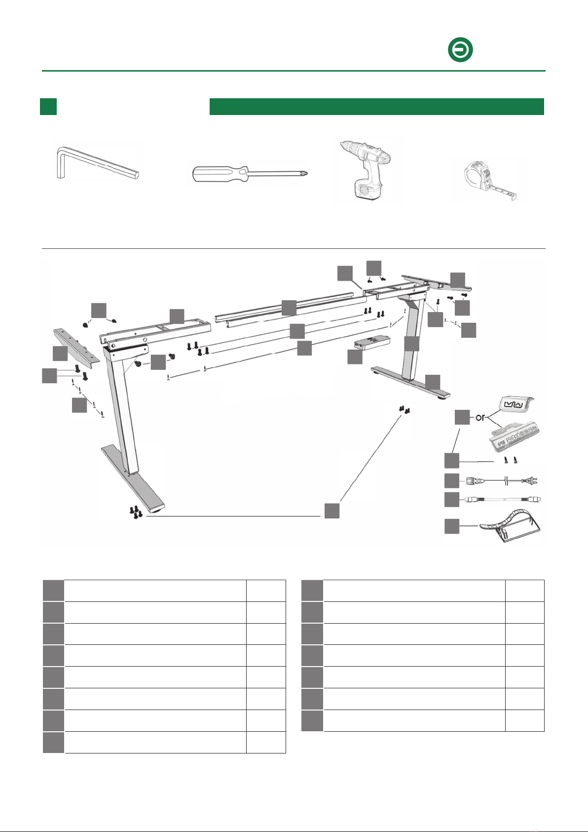
TOOLS / PARTS LIST
No. Part Qty
1Leg 2
2Foot 2
3a Frame End-CB 1
3b Frame End 1
4Center Rail 2
5Side Bracket 2
6Control Box 1
7Handset 1
No. Part Qty
8Power Cord 1
9Cable (1.3 m) 1
10 M6x10 Machine Screw 8
11 M6x14 Machine Screw 20
12 5x20 Wood Screw 11
13 5x16 Wood Screw 2
14 Cable Clip 10
13
13
"
E**:%
:
69
&&
2* AC
#$ "
/ 7
7 +C 7
F =*D2 /
F =* /
E A /
. /
. = /
G /
H /
8 ;& /
I 6/F*9 /
/4 AGJ/4A! 8
// AGJ/EA! /G
/7 AGJF.A! E
/F A.J74& H
/E A.J/G& 7
/. ** /4
"
E**:%
:
69
&&
2* AC
#$ "
/ 7
7 +C 7
F =*D2 /
F =* /
E A /
. /
. = /
G /
H /
8 ;& /
I 6/F*9 /
/4 AGJ/4A! 8
// AGJ/EA! /G
/7 AGJF.A! E
/F A.J74& H
/E A.J/G& 7
/. ** /4
11
11
11
11
10
12
12
5
4
3b
3a
6
2
11 5
12
11 11
1
7
8
9
14
13

BMB
4/10
e-mo-desk, two engines, 600-1250mm / 700-1200mm
Art.-No. 4884.617, 4884.618, 4884.666, 4884.688,
4884.717, 4884.718, 4884.766, 4884.788
l
2
3
4
5
ASSEMBLY
C
-1
>
a I
10 o/
I '
0
l)
l ).
l)
l
l) l
l
0
0
l l)
&
2)
l
1. Lay out all components and hardware to ensure that you have all the components and hardware
listed on the parts page. Slide the Control Box off the Frame End-CB and set aside. Fully
separate Frame End from Frame End-CB .You will find the Center Rails inside.
2. Place one of the Legs into the Frame End-CB ensuring that the
bar (arrow) is on "top" in relation to the Leg . Line up the holes on the
Leg with the holes on the Frame End-CB . Using the supplied Allen
Wrench, insert four M6x14 Machine Screws through the holes
in the Frame End-CB , going into the Leg and rotate each screw
just a few turns. After all four M6x 14 Machine Screws are
inserted, tighten all four screws.
Do the same for the other Leg and the Frame End .
3. The Frame End-CB should be placed on the side of the desk where
you plan to mount the Control Box and the Handset .
Slide the Side Bracket into the Frame End-CB . Insert two M6x14
Machine Screws through the two holes in the bottom of the frame
end/leg assembly and into the tabs in the Side Bracket . Using the
supplied Allen Wrench, rotate each screw just a few turns.
After both M6x14 Machine Screws are inserted, tighten both
screws.
Do the same for the other frame end/leg assembly.
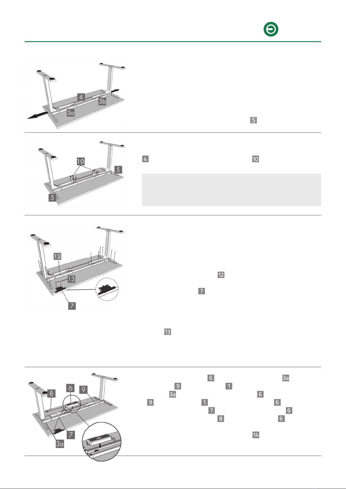
4. Slide the two Center Rails into the two
Frame Ends and ensuring:
a) the slots in the Center Rails face inward
b) the slots in the Center Rails are closer
to the top edge when the assembly is
upside down (see inset).
5. For each leg assembly, attach a Foot with four M6x14
Machine Screws and tighten in a cross-pattern.
ASSEMBLY
BMB
e-mo-desk, two engines, 600-1250mm / 700-1200mm
Art.-No. 4884.617, 4884.618, 4884.666, 4884.688,
4884.717, 4884.718, 4884.766, 4884.788
5/10
6. Your desktop may or may not be pre-drilled. Check both sides
of the desktop before placing the desk base on the underside
of the desktop.
Adjust the width of the desk base to fit the desktop by sliding
the two halves outward. We recommend leaving at least 1/2" of
the desktop width (on each end) protruding beyond the frame
width and centering the Side Brackets fore and aft.
7. If the desktop is pre-drilled, perform Step 8 before Step 7. If the
desktop is not pre-drilled, lock the position of the Center Rails
using eight M6x10 Machine Screws .
8. Double-check that the wood screws are not too long for
your desktop and won't puncture the surface when screwed
all the way in. Double-check that the desk base is properly
positioned on the underside of the desktop.
Attach the desk base to the underside of the desktop using
eleven 5x20 Wood Screws .
Attach the Handset so the front of the handset is flush with
the front desktop edge (or recessed up to 4 mm). The handset
may be placed anywhere along the front edge of the desktop
but we recommend placing it toward an end so it does not
interfere with your chair when seated. Use two 5x16 Wood
Screws to attach the handset to the desktop.
Do not overtighten screws in this step. Overtightening could
cause damage to the components.
9. Slide the Control Box onto the Frame End-CB . Connect
the cable exiting the Leg that is attached to the Frame
End-CB directly into the Control Box . Connect the Cable
to the other Leg and to the Control Box .
Connect the Handset cable to the Control Box .
Connect the Power Cord to the Control Box .
Use the adhesive-backed Cable Clips to secure the cables
so they do not sag.
We recommend that you pre-drill any holes needed for
fasteners if your desktop is not pre-drilled. Never use
countersunk screws.

BMB
6/10
e-mo-desk, two engines, 600-1250mm / 700-1200mm
Art.-No. 4884.617, 4884.618, 4884.666, 4884.688,
4884.717, 4884.718, 4884.766, 4884.788
10. Turn the assembled desk right-side up. With at least two people, grab the desk base (not the
desktop) and turn the desk right-side up. Adjust the pre-installed glides on the Feet as needed.
11. Plug the Power Cord into a 230V-outlet.
Make sure
- no obstacles are in the desk's path,
- the desktop is not touching any walls,
- all cords are appropriate length to accommodate the change in height.
IMPORTANT: You must RESET the desk prior to use.
RESET procedure: Press and hold the DOWN button on the Handset (part 7) until the desk
reaches its lowest height. Release the DOWN button. Press and hold the DOWN button again
(5 seconds on LED handset models, 10 seconds on non-LED handset models) until the LED dis-
play reads "RST". Release the DOWN button. Press and hold the DOWN button again until the desk
lowers a little bit more, slightly rises and stops. Release the DOWN button. Your desk is now ready
to use.
CAUTION: A RESET procedure requires the desk base to full retract (beyond any lower limit set).
Please ensure that you have the proper clearance below the desk base.
To program up to four presets (on some models):
Use the up/down buttons to find a desired height, then press M followed by a number 1 - 4.
USE

BMB
e-mo-desk, two engines, 600-1250mm / 700-1200mm
Art.-No. 4884.617, 4884.618, 4884.666, 4884.688,
4884.717, 4884.718, 4884.766, 4884.788
7/10
Press the DOWN button on the handset (part 7) until the base reaches its lowest position.
Measure the height of the base from the floor and if the number on the LED display does NOT match
your measurement, follow these steps:
Press and hold the DOWN button again until the LED display reads "RST". Press and hold the M button
about 5 seconds until the LED displays the flashing starting height (If the display returns to "RST"
before the next step is taken, repeat this step.).
Use the UP/DOWN buttons to change the value of the starting height so that it matches your measure-
ment. Once the new value is displayed, wait about 5 seconds and the display will return to "RST".
Finish the reset process by pressing and holding the DOWN button again until the desk lowers a little bit
more, slightly rises and stops. Release the button. The new starting height value is saved and your desk
is now ready to use.
Note: the LED display has a ± 0.1 tolerance.
SETTING THE LED RETRACTED HEIGHT (
some models
)
PROGRAMMING (
some models
)
Press the DOWN button on the handset (part 7) until the base reaches its lowest position.
Press and hold the DOWN button again until the LED display reads "RST". Press and hold the 1 button
(about 5 seconds) while the LED display flashes "RST" and then switches to either:
10.1 = One-Touch
10.2 = Constant-Touch
Release the 1 button. Press the 1 button again until the desired setting is reached. Once the chosen set-
ting is displayed, release the button and wait about 5 seconds for the display to return to "RST".
Finish the reset process by pressing and holding the DOWN button until the desk lowers a little bit more,
slightly rises and stops. Release the button. The new program setting is saved and your desk is now
ready to use.
CHANGING ANTI-COLLISION SENSIVITY (
some models
)
Press the DOWN button on the handset (part 7) until the base reaches its lowest position.
Press and hold the DOWN button again until the LED display reads "RST". Press and hold the UP button
(about 5 seconds) while the LED display flashes "RST" and then switches to either:
10.5 = 10 kg pressure (most sensitive)
10.6 = 15 kg pressure (middle setting)
10.7 = 20 kg pressure (least sensitive)
Release the UP button. Press the UP button again until the desired setting is reached. Once the chosen
setting is displayed, release the button and wait (about 5 seconds) for the display to return to "RST".
Finish the reset process by pressing and holding the DOWN button until the desk lowers a little bit more,
slightly rises and stops. Release the button. The new anti-collision sensivity is saved and your desk is
now ready to use.

BMB
8/10
e-mo-desk, two engines, 600-1250mm / 700-1200mm
Art.-No. 4884.617, 4884.618, 4884.666, 4884.688,
4884.717, 4884.718, 4884.766, 4884.788
This base is designed to go to its minimum and maximum heights, allowing for the widest possible
range. If you prefer to change the settings to a more narrow range, follow these steps:
Make sure the power is ON and a number reads in the LED display (if no number appears, please follow
the Reset procedure described in the USE section).
To set the upper limit position:
Use the UP/DOWN buttons to move the base to the desired maximum height position. Make sure the
UP button was the last button you pushed. Press the M button and release. Press the UP button and
release. The LED display will flash "S -". Press and hold the M button (about 2 seconds) until the LED
display changes to "999". The display will automatically return to the selected height. The new upper
limit is now set.
To set the lower limit position:
Use the UP/DOWN buttons to move the base to the desired minimum height position. Make sure the
DOWN button was the last button you pushed. Press the M button and release. Press the DOWN button
and release. The LED display will flash "S -". Press and hold the M button (about 2 seconds) until the
LED display changes to "000". The display will automatically return to the selected height. The new
lower limit is now set.
To remove the upper/lower limit positions:
Use the UP or DOWN button to move the desk to any new position. Press and hold the M button until
the LED display flashes "S -" and release. Within 5 seconds, press and hold the M button again (about
2 seconds) until the LED display changes to "555". After a few seconds, the display automatically will
change back to the numbered height position. The upper and lower limits are now removed.
After the upper and lower limits are set, the previous memory positions (1, 2, 3, 4)
may be outside the new range of movement. If so, simply reset the memory positions.
If you attempt to revise a previously set upper or lower limit and it is outside of the
existing range, you will need to remove the previously set upper/lower limits first.
SETTING THE UPPER AND LOWER LIMITS (
some models
)
To lock the handset:
Press and hold the M button (about 8 seconds) until the LED display switches to "S-" and then to "LOC".
Release the button. The handset is now locked.
To unlock the handset:
Press and hold the M button (about 8 seconds) until the LED display switches from "LOC" to the height
display. Release the button. The handset is now unlocked.
TO LOCK/UNLOCK THE HANDSET (
some models
)
BMB
e-mo-desk, two engines, 600-1250mm / 700-1200mm
Art.-No. 4884.617, 4884.618, 4884.666, 4884.688,
4884.717, 4884.718, 4884.766, 4884.788
9/10
If your desk is not functioning properly it may need to be reset. Follow the RESET procedure outlined in
the USE section on page 6.
If the height between the Legs exceeds 3,81 cm, stop the RESET procedure and contact your seller.
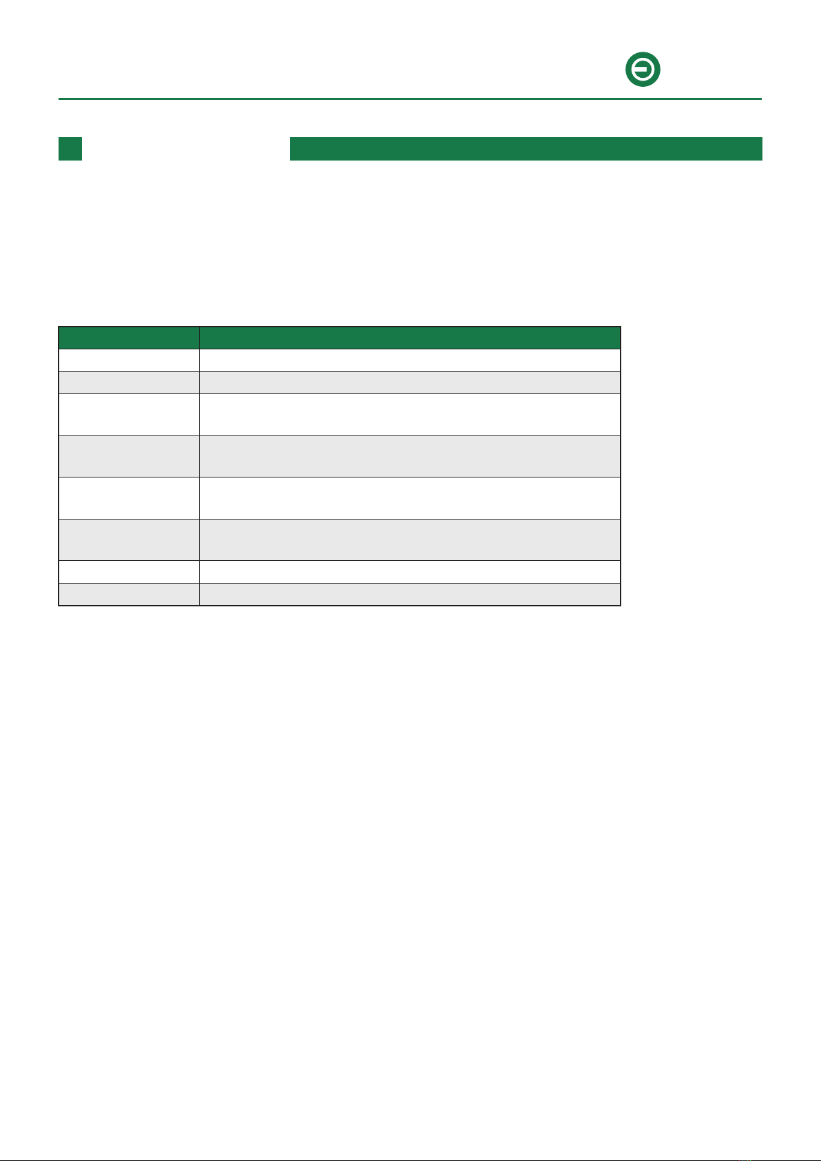
TROUBLESHOOTING
If your desk has a handset with an LED readout:
Error code Trouble shooting
000 Change the handset.
888 Change the handset.
E07 - E09 Switch the sides of Control Box to connect, then perform the
RESET procedure.
E13 Disconnect the power plug from the Control Box and plug it
in again.
ER1 - ER13 Check all electronic connections (Table Legs - Cable, Cable -
Control Box), then perform the RESET procedure.
H01 Let the base rest for 18 min. / Disconnect the power plug
from the Control Box and plug it in again.
LOC Unlock the handset.
RST Perform the RESET procedure.
If the error message persists, contact your seller.

BMB
10/10
e-mo-desk, two engines, 600-1250mm / 700-1200mm
Art.-No. 4884.617, 4884.618, 4884.666, 4884.688,
4884.717, 4884.718, 4884.766, 4884.788
BMB Beschläge GmbH • www.bmb-beschlaege.de • Reserve technical changes • As of: 06/2019 V4.2
Seller
Table of contents
Popular Indoor Furnishing manuals by other brands


Smart Comfort
Smart Comfort Leroy Lounge 3 Seater Assembly instructions

Rockler
Rockler Blum 56399 instructions

WASHTOWER
WASHTOWER WSCH26-45 Assembling Instruction

Broyhill
Broyhill Calcolo Marble IC7275 Assembly instruction

Tauris
Tauris BROADWAY1800 Assembly & instruction manual

MAISONS DU MONDE
MAISONS DU MONDE NOUMEA 165977 manual


