BMI Power Badger User manual

1
Model: 1800US
Product Manual
Thank you for your purchase of the Power Badger product!
The Power Badger was engineered to be rugged, long lasting and easy to use. We are grateful you
have put your trust in our company and chosen to invest your hard-earned money in our product.
Table of Contents:
Page 1 (this page)
Page 2-3: Initial plug-in, setting-up your Badger for the first time
Page 4: Power Badger Operation and Hidden Displays
Page 5-6: General Information
Page 7: Power Badger Term Definitions
Page 8: Device Map Page
Page 9: Device Features
Page 10: Parts List
2
Initial plug-in, setting-up your Badger up the first time:
(and/or after an internal battery change)
The first time you plug in your Power Badger you will be prompted to make a few initial settings These
settings will be saved (via the Badger’s internal battery) for a period of 4-6 months, so you don’t have to
make these setting selections more than once per winter season and you don’t have to set it up outside in
the cold. You can set-up your Badger indoors and then bring it outside when ready to use. All your settings
will be saved.
Follow the steps below (in the sequence given) to set up your Badger for the first time:
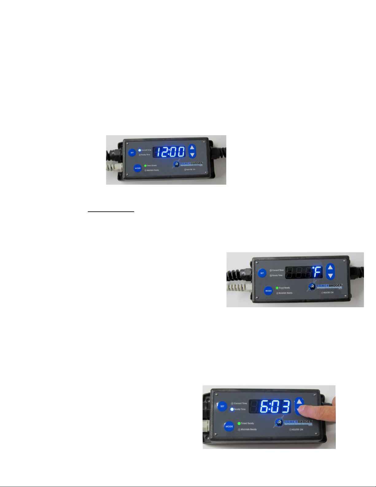
1). Plug in the device: Display flashes “12:00” in conjunction with the “Current Time” LED indicator.
2). Set current time:
Use the up/down selection buttons (on the right side of the device) to select the current time. Note: there
is a “PM” indicator in the lower right corner of the display that will illuminate when a PM time is selected. If
the “PM” indicator is not illuminated, then the time displayed is AM time. Once desired time is selected,
press the “Set” button. The current time is now saved and the device prompts you to make a temperature
units selection; see next step.
3). Select degrees Celsius (°C) or degrees Fahrenheit (°F):
Use up/down selection buttons to toggle between °C and °F
Once the unit type you wish to use is displayed, press the “Set”
button. The temperature units selection is now saved and the
device display now flashes “12:00” in conjunction with the
“Ready Time” LED indicator; prompting you to set the time you
desire the unit to have your engine ready to start; see next step.
*(*If you only intend to use your Power Badger in the “Maintain” mode, you may press the “Set” button to
bypass setting the “Ready Time”,… then skip to step 5.)
4). Set the desired “Ready Time”:
Use the up/down selection buttons to select the desired “Ready Time”. This will be the time that you want
your engine ready to start (be sure to mind the “PM” indicator for setting PM times).
Once desired “Ready Time” time is selected, press the
“Set” button. The current time is now saved and the
device displays “2 HR” and flashes the “Maintain Ready”
LED, prompting you to make a “maintain after ready”
selection of between 0 and 9 hours.

3
5). Set the “Maintain after ready” duration:
This selection controls how long the unit maintains your engine in a
“ready to start” condition after your selected “Ready Time” has
been reached (settable at 0-9 hours).
*Example: If you have the “Ready Time” on your Badger set to 6:00am, the “maintain after ready” duration
you select (0-9 hours), controls how long your unit will go into “Maintain” mode after 6:01am. If you select
“3HR” then your engine will be put in “Maintain” mode for 3 hours after the ready time….so, in this
example of “3HR” selected, the engine would be maintained in a ready to start condition until 9:00am. 9
hours is the maximum amount of time the unit can be set to maintain after a “Ready” event. If longer than
a 9 hour maintain duration time is desired, the Badger can be put permanently in “Maintain Mode”, as
discussed later in this manual.
To select the desired “maintain after ready” duration, use the up/down selection buttons to make your
selection of 0-9 hours. Once you have made your selection, press the “Set” button and the unit will display
“OFF”. This concludes the user defined selection and setting process.
6). Set your desired Mode:
Next, using the “Mode” button, you will set the mode that your Badger will operate in. Each press of the
mode button will scroll to the next operational mode of the device. Illustrations below show examples of
what the screen and LED’s will look like in each of the 4 modes:
See General Operation section (next page) for further information on modes.
OFF Mode: Timed Ready Mode:
Maintain Ready Mode: On Mode:

4
Power Badger Operation
Mode Selection:
Press the “Mode” button, to toggle through the 4 different modes of your Power Badger. Each press of the
Mode button will scroll to the next choice. Once the desired choice is displayed, no further action is needed,
the device is then in that mode of operation.
Your choices are:
1). OFF: unit is powered and ready but will take no action.
2). Timed Ready: The device will have your engine ready to start at your set “Ready Time”. The “Timed
Ready” LED will remain illuminated. The time related LED’s and display will cycle through the following
sequence when in this mode: current time, ready time, current temperature.
3). Maintain Ready: The device will maintain your engine in a ready-to-start condition in perpetuity. The
“Maintain Ready” LED will remain illuminated and the display will scroll the current temperature and
“rEdy”, indicating the engine is being maintained in a ready-to-start condition.
4). Constant ON: The device will supply constant power to the heater without further control (in
perpetuity).
More information on each particular mode can be found on page# 7 (Power Badger Term Definitions).
Hidden Menu Display Readouts:
The hidden readouts are only accessible when the device is in the “Constant ON” mode and red “heater on”
LED indicator is illuminated:
•Total Relay Cycles;(must be pressed in this order); First, press the “up” button, then press
“Mode” button – displays total relay cycles. Displays the total number of times the relay has cycled
over the (current battery) lifetime of the unit. Press any key to escape this mode.
•Total Energy Hours Saved;(must be pressed in this order); First, press the “down” button, then
press “Mode” button – displays total hours saved. Displays the total number of hours saved over the
(current battery) lifetime of the unit. This calculation is based upon time that the unit is plugged in,
but not feeding power to the heater, thereby calculating time (that without the Power Badger unit)
the heater would otherwise be using power. Press any key to escape this mode.

5
General Information
Location: The Power Badger unit must be in approximately the same temperature environment as the
engine heater it will be controlling. It is best to keep the unit out of direct sunlight, as the direct sunlight
can affect the measured temperature readings at the unit. If the vehicle being controlled is in the direct
sunlight, then just underneath the vehicle it is controlling is a good spot for the Badger. The Badger
calculates firing times and duration algorithms based upon temperature readings in its ambient
environment. If the observed temperature at the Power Badger is different than where the engine is
located, then the calculations will not be as intended and the result could be an engine that is not as ready
to start as intended.
Internal Battery: The Power Badger contains an internally mounted lithium battery (CR2032) that allows
the unit to save the user settings for a period of up to 6 months without external power. Once this battery
becomes depleted and user settings (such as the current time) are no longer retained, it will be necessary to
replace the internal battery.
Battery Change Instructions: The internal battery is a standard CR2032 button cell, readily available at
most battery retailers.
To replace the internal memory retention battery:
1). Unplug the Power Badger from 120v Power
2). Remove the 6 Phillips head screws that retain the back cover.
3). Remove the back cover
4). On the battery holder; carefully lift the top battery retaining tab slightly away from the battery and
slide the battery out. Be careful not to bend the retaining tab too much or it will no longer retain the
battery upon re-installation.
5). Slide the new CR2032 battery under the tab and be sure it is seated in the battery holder properly. Be
sure the flat positive (+) side of the battery (the side with the part# on it) is facing up and in good contact
with the top retaining tab.
6). Carefully replace the rear cover gasket into the enclosure groove, replace rear cover and re-attach cover
using the 6 Phillips head screws that were removed during step 2.
7). Follow instructions on page 2 for setting-up your user defined settings.
Internal Fuse: The Power Badger is equipped with an internal fuse to keep your unit safe in the event of
an overload condition. Common causes of an overload condition can be:
a). more than 1800 watts of load on the Badger
b). failed/electrically shorted engine heating element
c). internal water intrusion into the Badger’s enclosure

6
Internal Fuse Change Instructions: The internal fuse is a standard 20 amp 250v (Bel Fuse#3AB20 or
Littelfuse#0314020.MXP) readily available at most electrical parts retailers.
To replace the internal fuse:
1). Unplug the Power Badger from 120v Power
2). Remove the 6 stainless steel Phillips head screws that retain the rear cover.
3). Remove the rear cover. The fuse is cylindrical and made of white ceramic, located next to where the
output cord exits the enclosure.
4). Carefully lift one end of the fuse and remove (using a small screwdriver or the like). Be careful not to
bend the retaining tabs or the will no longer retain the fuse properly upon re-installation.
5). Install the new fuse within the tabs and be sure it is seated in the fuse holder properly.
6). Carefully replace the rear cover gasket into the enclosure groove, replace rear cover and re-attach cover
using the 6 Phillips head screws that were removed during step 2.
Wind: High wind conditions can take heat from the engine compartment and make the engine more
difficult to warm. It is preferable to protect the vehicle’s engine from the wind as much as possible. Even
putting the front of the vehicle near the wall of a building or other vertical surface higher than the grille
can help maintain engine heat.
Heaters Type: The Power Badger Model 1800US is designed to power up to 1800 watts of resistive type
load, such as: Engine block heaters, Battery blankets/pads, Oil, fuel and Oil pan mounted heaters. These
heaters must be suited to their application and sized properly for their intended use, otherwise dangerous
conditions could result. Regardless of whether the Power Badger to controls these devices or not, the
heaters installed on a vehicle or on/in an engine must be sized and suited properly for their application.
In the Event of a Power Outage: If power is interrupted during operation, once the power returns, the
Power Badger is programmed to continue the same mode of operation as it was in when the power failed. If
the unit was in “Timed Ready” mode when the power failed, the unit will resume operation to ready the
engine for its intended start time, but if the power outage was too long, the unit may not have enough time
to fully prepare the engine to start as intended. In the same way, if the unit was in “Maintain Ready” mode
when the power failed (and the power was out for too long) the unit may not be able to restore the engine
to a “start-ready” state (depending upon the ambient temperature).

7
Power Badger Term Definitions
Modes Defined:
1). OFF: unit is powered and ready but will take no action.
2). Timed Ready: The device will have your engine ready to start at your set “Ready Time” based upon the
observed temperature and the “Ready Time” setting. The Power Badger will use the minimum amount of
power necessary to get the engine fully ready to start at your desired “Ready Time”. The Badger will
automatically repeat the programmed ready cycle every day until changed or unplugged.
3). Maintain Ready: The device will maintain your engine in a ready-to-start condition in perpetuity.
4). ON: The device will supply constant power to the heater without further control (in perpetuity).
Maintain after ready:
This selection controls how long the unit maintains your engine in a “ready to start” condition after your
selected “Ready Time” has elapsed. This is a user selectable parameter of between 0 hours and 9 hours.
*Example: If you have the “Ready Time” on your Badger set to 6:00am, the “maintain after ready” duration
you select (0-9), controls how long your unit will go into “Maintain” mode after 6:01am. If you select “3HR”
then your engine will be put in “Maintain” mode for 3 hours after the ready time….so, in this example of
“3HR” selected, the engine would be maintained in a ready to start condition until 9:00am. 9 hours is the
maximum amount of time the unit can be set to maintain after a “Ready” event. If longer than a 9 hour
maintain duration time is desired, the Badger can be put permanently in “Maintain Mode”, as discussed later
in this manual.
Ready Time:
“Ready Time” is a user defined setting, defining at what time the Power Badger device will aim to have the
engine ready to start. The device will use the (user defined) ready time along with the outside temperature
measurements to calculate when to fire the engine heater and for how long.
Maintain Ready Mode:
The function of the “Maintain Ready” mode is to keep (or maintain) an engine that is already ready to run
in a startable condition (ie..vehicle was just parked after running or was just brought up to temperature by
the “Ready” mode). The Power Badger device senses the outside temperature and calculates a firing duty
cycle algorithm designed to use the minimum amount of electricity necessary to maintain the engine in a
startable condition. To achieve this, the microprocessor inside the Badger divides that cycle into segments
of on and off, based upon the measured outside temperature. The Badger will automatically maintain the
engine in a startable condition, in perpetuity, until changed or unplugged.

8
Device Map
1: Temperature sensor inside protective strainer (light colored to reduce sun heat from affecting readings)
2: Mounting holes on enclosure to screw to wall or vehicle
3: Input power cord strainer
4: Mode button; used to select operational mode of device
5: Set button; set time of day, temp units (°F or °C), start/ready time and maintain duration time
6: Timed Ready LED; illuminated when the unit is set in timed ready mode. Display shows the
user set start/ready time (the time the device will have the engine ready to start).
7: Maintain Ready LED; illuminated when the unit is set in maintain ready mode. Display shows
current temperature.
8: Digital display
9: Heater on LED; Illuminated whenever power is being supplied to the output cord
10: Up select button; used to adjust settings in conjunction with set button
11: Down select button; used to adjust settings in conjunction with set button
12: Output power cord strainer

9
Device Features
The Power Badger was carefully engineered to be rugged and long lasting. We want the owners of the Power
Badger to know that their unit is well built. We assemble every unit right here in North Carolina, USA, using no-
compromise, high quality components that (in many cases) were engineered and produced specifically and
exclusively for the patent pending Power Badger product. The Power Badger has been extensively tested for
functionality and durability down to -50°F / -45°C.
Here we list some of the features and details of the product that may not be readily apparent at first glance:
1). Mounting Screws: the 6 rear mounting screws are made of high quality stainless steel
2). Temperature Sensor: clad in stainless steel and uses premium silicone wire (for flexibility in extreme cold)
3). Sensor Strainer: the grey strainer that contains the temperature sensor is made of a special low temperature
plastic that resists shattering in the extreme cold. The strainer is grey in color to reduce the effect that direct sunlight
may have on the temperature reading at the sensor.
4). Circuit Board:has a special coating on selected surfaces to resist damage from internal water intrusion and
condensation
5). Cords: both the (15 amp rated) input and output cords use specially formulated low-temperature rubber sheathing
for maximum flexibility in extreme cold conditions.
6). Front Membrane:uses a very thick and durable Lexan substrate and 3M’s latest and best VHB industrial adhesive.
These premium materials coupled with the stainless rivet nails that hold down the corners of the front membrane offer
the best durability and low-temperature functionality available.
7). Enclosure:made of a special low-temperature poly blend plastic with fiber additive, engineered to be rugged in
extreme low temperatures. The enclosure also features reinforced “feet” cast into the mold that allows the bottom of
the unit to stand off the ground slightly, helping to reduce water intrusion. These feet also have holes cast through
them to allow permanent mounting of the unit on a wall or a vehicle.
8). Rear Cover Gasket: a form-fitting gasket seals the aluminum rear cover to the enclosure for water resistance.
9). LED Display: the Badger’s specially designed low-temperature LED display will look just as bright at -50°F / -45°C
as it does at room temperature. The unit is programmed to save power and extend the life of the LED’s and display by
dimming after 10 seconds of no keys being pressed.
10). Strainers: all through-holes in the enclosure (for cord and sensors) use weather-tight strainers featuring an
internal clamping mechanism (on their respective cord) and an external rubber gasket to seal out moisture.
11). Fuse and Battery Holders: the internally mounted battery and fuse holders are specially designed to retain their
respective parts through hard external impact situations.
12). Development and Testing: after many revisions to increase durability and reliability; the final electronic
hardware and firmware versions were mercilessly tested at sub-zero temperatures through 10,000+ resets, power
interruptions and physical abuse to assure flawless electronic performance during the harshest of conditions.
13). Internal Transformer:(inside the unit) is designed to be as low-profile as possible with many attaching points to
the board, so this important (and relatively heavy) component does not come off the board during very rough handling
at cold temperatures.
14). Rear Cover: made of thick, high quality laser cut aluminum that has been specially coated and laser etched for
durability and longevity.

10
Parts List
Power Badger Model# 1800US Replacement Parts List
Part number
Description
Qty per unit
PB1001
Enclosure / Housing
1
PB1002
Bottom / back aluminum cover
1
PB1003
Front membrane / face
1
PB1006
PCBA assembly, w/blue display
1
PB1007
Input power cord / 120v / male
1
PB1008
Output power cord /120v / female
1
PB1009
Thermistor / temperature sensor
1
PB1010
Input/output cord strainer M20 / black
2
PB1011
Thermistor cord strainer / M16 /grey
1
PB1018
Bottom / back cover stainless mounting screw
6
PB1019
Bottom / back cover to enclosure, molded gasket
1
PB1021
Front membrane / face, stainless nails
4
© Bostic Motors Inc. 2017 (all rights reserved)
157 N Main St.
Bostic, NC 28018
PH# 828-453-7779

11
Power Badger™ Limited Warranty
Limited Warranty - This limited warranty is expressly limited to Bostic Motors Inc’s products (hereafter referred to as
“The Company”) that have been purchased by the original consumer purchaser or for purposes of resale or in the
ordinary use by the end-user. The term original consumer (end-user) purchaser is defined as the person who purchases
Company products for personal, residential or business use.
The Company's products are warranted against defects in materials and workmanship for a period of one year from
date of purchase by consumer / end-user. The exclusive remedy for any product found to be defective during this
limited warranty period consists of the repair or replacement of the defective product. This limited warranty does not
apply to defects which arise from normal wear and tear, accident, misuse, abuse, neglect, mishandling, misapplication,
faulty installation, modification, improper or extraordinary use or use inconsistent with any instruction or
recommendation issued by the Company.
The foregoing limited warranty is exclusive and in lieu of all other warranties, whether written or oral, express, implied
or statutory.
NO IMPLIED WARRANTY OF MERCHANTABILITY OR FITNESS FOR A PARTICULAR PURPOSE SHALL APPLY. THE LIMITED
WARRANTY CONTAINED HEREIN DOES NOT EXTEND TO INCIDENTAL OR CONSEQUENTIAL DAMAGES RESULTING FROM
THE USE OF THIS PRODUCT, OR ARISING OUT OF A BREACH OF THIS WARRANTY.
To obtain performance of this limited warranty, the alleged defective product must be returned, together with
reasonable proof of purchase, written explanation of the problem and postage or freight prepaid, directly to:
In U.S.A & Canada:
Bostic Motors Inc, Attn: Warranty Claims
157 North Main St.
Bostic, NC 28018
The Company will return the repaired or replaced product, postage or freight prepaid. Final determination of defects
shall be made in accordance with procedures established by the Company.
This limited warranty gives the original consumer purchaser specific rights. You may have other rights which vary from
state to state or province to province depending upon the location of your residence. Some states do not allow the
exclusion or limitation of incidental or consequential damages.
Manufacturer's rights retained: The Company reserves the right to make changes in design, additions or improvements
to any of Its products at any time without incurring any obligation whatsoever to install or replace the same or improve
upon products previously manufactured.
Bostic Motors Inc. - Rev. 09/2017
This manual suits for next models
2
Table of contents
Popular Automobile Accessories manuals by other brands


DK2
DK2 CHPW102 instruction manual

Idle Free
Idle Free Flex Operator's handbook

Romik
Romik 2137 2D installation instructions

Safe Fleet
Safe Fleet PRIME DESIGN VRR3-E-PM11 manual

Xpresskit
Xpresskit DBALL2-HYUNDAI9 Installation and quick reference guide

Auto Care Products
Auto Care Products Park Smart Clean Park quick start guide


