BMI Schiedel RITE-VENT ICID PLUS User manual

100 - 200mm Internal Diameter
Twin Wall Insulated Chimney System for gas, oil, wood and
multi-fuel applications (including condensing applications)
ICID PLUS
INSTALLATION INSTRUCTIONS
Part of BMI Group
SAP Version 3 940002165 November 2017
CONTENTS
2
APPROVALS
ICID Plus is CE Certied to EN1856-1 TÜV 0036 CPR 9195 010 with designations:
ICID Plus is CE Certied to EN1856-2 TÜV 0036 CPR 9195 042 with designations:
* For full information please see p.8 - Distance to Combustibles Section
• Manufactured under a Quality Management Scheme approved to BS EN ISO 9001
• 4 Hour Fire Rating to BS476 Part 20
• Certied for corrosion resistance on gas, oil and solid fuel by Gastec, MPA and TÜV
• HETAS listed for use on solid fuel applications.
APPROVALS
DESIGN GUIDE
- Mandatory Requirements
PRIOR TO INSTALLATION
- Ventilation
- Carbon Monoxide Alarms
- Painting
- Handling
- Delivery to Site and Storage
CONNECTING FLUE PIPE
- Appliance/Chimney Connection
- Provision for Condensate Disposal
- Connection to Draught Diverter
- Connecting Flue Pipe Diameter
- Distance to Combustibles
- Connecting Flue Pipe Route
- Inspection
BS EN 15287-1
ACCEPTABLE ALTERNATIVE
METHODS OF CONNECTION
SYSTEM CHIMNEY
- Chimney Diameter
- Chimney Route
- Connection to Draught Diverter
- Direct Connection Appliance
to System Chimney
- Distance to Combustibles
- Enclosures/Shafts
- Support Components
- Chimney Termination
- Terminals
Page 2
Page 3
Page 4
Page 5
Page 7
Page 8
Page 9
System Chimney EN1856-1
Connecting Flue Pipe EN1856-2
T450 N1 D V2 L50050 G100 M
T450 N1 W V2 L50050 G60
T450 N1 D V3 L50050 G60
60mm Distance to combustibles
in a combustible shaft*
T450 N1 W V2 L50050 G50
T450 N1 D V3 L50050 G50
50mm Distance to combustibles
in a non combustible shaft or in free air*
T200 P1 W V2 L50050 O00
Zero distance to combustibles*
INSTALLATION
INSTRUCTIONS
- Jointing System
- Standard Chimney Sections
- Gasket Kits
- Individual Components
OFFSET DIMENSIONS
FIRESTOP COMPONENTS
OUTLET SITING
TYPICAL EXTERNAL
INSTALLATIONS
LOAD BEARING DATA
COMPONENT WEIGHTS
AFTER INSTALLATION
- Testing and Commissioning prior to rst use
- Appliance Operation
- Multi-Fuel Applications
- Maintenance
- Fuel Storage and Usage
NOTICE PLATE
PRODUCT GUARANTEE
- Product Registration
- QR for Installation Assistant
App download
- QR link for Online
Guarantee Registration
Page 10
Page 18
Page 19
Page 31
Page 32
Page 33
Page 34
Page 35

DESIGN GUIDE
PRIOR TO INSTALLATION
3
Mandatory Requirements
Connection to an appliance which is not connected to the fuel supply, should be carried out by a competent person. We
recommend the use of HETAS approved installers for solid fuel applications. If installation is carried out by a non HETAS
registered installer, the installation must be certied by a local Building Control inspector. Connection to an appliance that is
connected to the fuel supply must be carried out by a Gas Safe (Gas) or OFTEC (Oil) registered installer.
The design guide must be read in conjunction with the detailed component installation instructions. For full design and
installation details the key referral documents are:
•BSEN1856-1: Chimneys - System Chimney Products
•BSEN1856-2: Connecting Flue Pipes
•BSEN1859: Metal Chimneys - Testing Methods
•BSEN1443: Chimneys - General Requirements
•BSEN15287-1: Chimneys. Design, installation and commissioning of chimneys. Chimneys for non-room sealed heating appliances.
•BS5440-1: Fluing and ventilation for gas appliances of rated input not exceeding 70kW net (1st, 2nd and 3rd family gases).
Specication for installation of gas appliances to chimneys and for maintenance of chimneys.
•ApprovedDocumentJ: - Combustion appliances and fuel storage systems (England & Wales)
•DFPTechnicalBookletL: - Combustion appliances and fuel storage systems (NI)
•TechnicalHandbook(Domestic&NonDomestic),Section3 - Environment (Scotland)
•ApplianceInstallationInstructions and related standards. Other standards covering specic applications will also
be relevant and must be adhered to.
Planning permission may be required, and reference should be made to the local Building Control Department.
Ensure all chimney components are available and check them to ensure there has been no damage. Do not use damaged
components. Build the chimney up through the previous designed route which should be as straight as possible.
Ventilation
It is very important that sufcient air for combustion and ventilation is provided to the room containing the appliance, to enable
correct and efcient working of the appliance and chimney system. Reference should be made to the appliance manufacturer’s
instructions and recommendations are also given in the Building Regulations Document J, CIBSE guidance notes and BS 5440.
CarbonMonoxideAlarms
The carbon monoxide alarms should comply with BS EN 50291
Where a new or replacement xed solid fuel appliance is installed in a dwelling, a carbon monoxide alarm must be provided
in the room where the appliance is located.
Please follow manufacturers instructions with regards to siting and xing or alternatively :-
a) On the ceiling at least 300mm from any wall or if it is located on a wall, as high up as possible (above any doors and
windows), but not within 150mm of the ceiling and
b) between 1m and 3m horizontally from the appliance.
N.B Provision of a carbon monoxide alarm should not be regarded as a substitute for correct installation and regular servicing.
Painting
If painting of any external sections is required, it is important to de-grease, dry and prime the exterior surface prior to the
application of appropriate heat resistant paint. Schiedel Chimney Systems can provide to special order, chimney sections and
accessories painted to an extensive range of British Standard RAL colours – details on application.
Handling
It is advised that suitable PPE should be used when handling the products.
DeliverytoSiteandStorage
Components should be carefully transported and off loaded. They should be inspected to ensure they have not been damaged,
and should be stored off the ground and under cover so that they are protected from accidental damage and the adverse
effects of weather.

Appliance/Chimney Connection
Connection to the appliance can be made using Prima Smooth, Prima Plus or alternative approved single wall connecting
ue pipes, or ICID Plus.
This must be done by using the appropriate appliance connector. When a single wall connecting ue pipe is used to
connect an appliance to the chimney, the lower end of the chimney section must extend a minimum of 425mm below
the ceiling. When connecting the appliance to the ue pipe all joints between the ue pipe/appliance outlet must be
securely caulked and sealed with non asbestos rope (or suitable alternative) and re cement on solid fuel appliances.
Any ue pipe connection to the chimney MUST be made in the same room as the appliance.
ProvisionforCondensateDisposal(subjecttoappliancemanufacturers’recommendations)
Condensing appliances need provision for drainage. Choose the appropriate ue drainage components normally tted
at the base of the vertical stack and/or close to the appliance outlet. Any ‘horizontal’ runs must allow for a minimum 3°
slope and therefore, where required, 87° bends and 93° tees must be used rather than 90° bends and tees.
ConnectiontoDraughtDiverter
Where the appliance features a draught diverter the connection should rise vertically from it for at least 600mm before
any change of direction (unless otherwise specied by the appliance manufacturer). This is in accordance with the
recommendations contained in BS 5440 Part 1 section 6.1.4
Connecting Flue Pipe Diameter
Connecting Flue Pipe Diameter size should be as recommended by the appliance manufacturer. Under all circumstances
the operational requirements of the appliance and the conguration of the ue must satisfy the ue sizing requirements
of EN13384-1.
DistancetoCombustibles
In accordance with building regulations, it is essential that the correct distance to combustible material is maintained
on connecting ue pipes. On solid fuel applications, where there is a risk of soot re, on unmeasured (NM) designated
single wall product, this distance is 3 x ØInt of the pipe, e.g. for Ø125mm the distance is 375mm and for Ø150mm the
distance is 450mm to combustibles on both painted and non painted variants. On measured (M) single wall or double wall
products this distance will be as declared by the chimney manufacturer. On ICID Plus this distance has been measured and
is set at 100mm.
Connecting Flue Pipe Route
Single wall connecting ue pipes should only be used to connect appliances to a Chimney. They should not pass through
any roof space, partition, internal wall or oor, except to pass directly into a chimney through a wall of the chimney.
Connecting ue pipes should be located as to avoid igniting combustible material.
On solid fuel appliances the maximum length of a connecting ue pipe is 2m. This distance is reduced to 1.5m if any of
the acceptable alternative methods of connection are adopted as per BS EN15287-1. (See p.5-6 for full details.)
On appliances with a top outlet, it is recommended that a vertical run of at least 600mm should be allowed immediately
above the appliance prior to any change of direction.
On appliances with a rear outlet, it is recommended that there is maximum of 150mm in the horizontal run however
under certain conditions, as described in alternative methods in BS EN 15287-1, this may be increased to 450mm. (See
p.5-6 for full details.)
Within a system (Chimney + Connecting Flue Pipe) there should be no more than 4 changes of direction of maximum 45˚.
90˚ Factory made bends or tees within the system may be treated as being equal to two 45˚ bends (as per Document
J of the Building Regulations issued October 2010).
Inspection
On solid fuel applications to conform to Building Regulations, provisions should be made to enable a chimney to be
inspected and cleaned.
An inspection pipe, inspection elbow or a 90° or 135° Tee with tee cap can form a suitable inspection point (unless
cleaning/inspection can be done through the appliance). To aid cleaning, sufcient distance should be left between changes
of direction to permit the safe passage of cleaning brushes within the system. This is particularly important on solid fuel
applications. It is recommended that chimneys serving solid fuel appliances be swept as frequently as necessary, but at
least twice a year.
4
CONNECTING FLUE PIPE

5
BS EN 15287-1
ACCEPTABLE ALTERNATIVE
METHODS OF CONNECTION
Where a horizontal connecting ue of more than 150mm is required to connect a solid fuel red appliance to a chimney,
an installation method as per the examples below may be used provided the following criteria is met:-
a)Themaximumlengthofhorizontalconnectinguepipedoesnotexceed450mm;
b)ADefraexemptapplianceoranappliance,whichislimitedtoburningauthorisedsmokelessfuelonly,isinstalled;
c)AcalculationaccordingtoBSEN13384-1hasindicatedsafeoperationoftheproposedconguration,andtheresults
ofthecalculationareleftwiththehouseholderalongwiththeapplianceinstallationinstructions;
d)Theappliancemanufactureragreesinwritingtotheproposedconguration;
e)Thechimneymanufactureragreesinwritingtotheproposedconguration;
f) Thetotallengthofsinglewallconnectinguepipeisnotmorethan1.5m;
g)Theappropriatedistancestocombustiblematerialsfromboththeapplianceandtheconnectinguepipearemaintained.
Top Outlet Single Wall Connecting
Flue Pipe through Solid Wall into
Twin Wall System Chimney
NB Where the connecting ue pipe from
the appliance passes through any wall other
than the existing chimney wall, the connecting
ue pipe must be a System Chimney of twin
wall insulated design.
Top Outlet Twin Wall Connecting
Flue Pipe through Solid Wall into
Twin Wall System Chimney
For minimum distance for
this configuration check
manufacturers distance
to combustibles
Measured from back
of appliance to outside
surface of chimney
Measured from back
of appliance to liner
of masonry chimney
Twin Wall
Chimney System
300
Wall Support
Tee Cap for
Debris Collection/
Cleaning Access
Wall Sleeve
Trim Collar
Cavity Wall Wall Band
450mm MAX 300
450mm MAX
External Masonry
Chimney System
Inspection/
Cleanout Door
Cavity Wall
Wall Sleeve
Trim Collar
Debris
Collector
Wall Sleeve
Trim Collar
100100
225 square
(9” x 9”)
Flexible Twin Wall
Chimney Liner
Chimney Wall
Support Bracket
Swept Elbow
Sweep access
Tee Piece
Single Wall to
Flex Connector
450mm
MAX
Measured from
back of appliance
to flue liner
Wall Support
Measured from back
of connecting flue
pipe to outside
surface of chimney
Tee Cap for
Debris Collection/
Cleaning Access
Twin Wall
Chimney System
Solid Wall
Inspection Bend
Wall Sleeve
Trim Collar
600 min
225
For minimum distance for
this configuration check
manufacturers distance
to combustibles
No further
bends allowed
on this
configuration
Wall Band
450mm MAX
Measured from back
of connecting flue
pipe to outside
surface of chimney
Tee Cap for
Debris Collection/
Cleaning Access
Twin Wall
Chimney System
Solid Wall
Inspection Bend
Wall Sleeve
Trim Collar
225
Wall Support
Wall Band
450mm MAX
600 min
For minimum distance for
this configuration check
manufacturers distance
to combustibles
No further
bends allowed
on this
configuration
Flexible Twin Wall
Chimney Liner
Inspection/
Cleanout Door
Inspection Bend
Wall Sleeve
Trim Collar
Chimney Wall
Support Bracket
Tee Piece
Tee Cap for
Debris Collection/
Cleaning Access
Single Wall to
Flex Connector
225 square
(9” x 9”)
450mm
MAX
For minimum distance for
this configuration check
manufacturers distance
to combustibles
For minimum distance for
this configuration check
manufacturers distance
to combustibles
For minimum distance for
this configuration check
manufacturers distance
to combustibles
Measured from back
of connecting flue pipe
to flue liner
No further
bends allowed
on this
configuration 600 min
100100

6
Top Outlet Twin Wall Connecting
Flue Pipe into Re-lined Masonry
Chimney
Rear Outlet Twin Wall Connecting
FluePipeThroughCavityWall
into Twin Wall System Chimney
Rear Outlet Twin Wall Connecting
Flue Pipe into Re-lined Masonry
Chimney
Rear Outlet Twin Wall Connecting
FluePipeintoExternalMasonry
ChimneythroughaCavityWall
For minimum distance for
this configuration check
manufacturers distance
to combustibles
Measured from back
of appliance to outside
surface of chimney
Measured from back
of appliance to liner
of masonry chimney
Twin Wall
Chimney System
300
Wall Support
Tee Cap for
Debris Collection/
Cleaning Access
Wall Sleeve
Trim Collar
Cavity Wall Wall Band
450mm MAX 300
450mm MAX
External Masonry
Chimney System
Inspection/
Cleanout Door
Cavity Wall
Wall Sleeve
Trim Collar
Debris
Collector
Wall Sleeve
Trim Collar
100100
225 square
(9” x 9”)
Flexible Twin Wall
Chimney Liner
Chimney Wall
Support Bracket
Swept Elbow
Sweep access
Tee Piece
Single Wall to
Flex Connector
450mm
MAX
Measured from
back of appliance
to flue liner
Wall Support
Measured from back
of connecting flue
pipe to outside
surface of chimney
Tee Cap for
Debris Collection/
Cleaning Access
Twin Wall
Chimney System
Solid Wall
Inspection Bend
Wall Sleeve
Trim Collar
600 min
225
For minimum distance for
this configuration check
manufacturers distance
to combustibles
No further
bends allowed
on this
configuration
Wall Band
450mm MAX
Measured from back
of connecting flue
pipe to outside
surface of chimney
Tee Cap for
Debris Collection/
Cleaning Access
Twin Wall
Chimney System
Solid Wall
Inspection Bend
Wall Sleeve
Trim Collar
225
Wall Support
Wall Band
450mm MAX
600 min
For minimum distance for
this configuration check
manufacturers distance
to combustibles
No further
bends allowed
on this
configuration
Flexible Twin Wall
Chimney Liner
Inspection/
Cleanout Door
Inspection Bend
Wall Sleeve
Trim Collar
Chimney Wall
Support Bracket
Tee Piece
Tee Cap for
Debris Collection/
Cleaning Access
Single Wall to
Flex Connector
225 square
(9” x 9”)
450mm
MAX
For minimum distance for
this configuration check
manufacturers distance
to combustibles
For minimum distance for
this configuration check
manufacturers distance
to combustibles
For minimum distance for
this configuration check
manufacturers distance
to combustibles
Measured from back
of connecting flue pipe
to flue liner
No further
bends allowed
on this
configuration 600 min
100100
For minimum distance for
this configuration check
manufacturers distance
to combustibles
Measured from back
of appliance to outside
surface of chimney
Measured from back
of appliance to liner
of masonry chimney
Twin Wall
Chimney System
300
Wall Support
Tee Cap for
Debris Collection/
Cleaning Access
Wall Sleeve
Trim Collar
Cavity Wall Wall Band
450mm MAX 300
450mm MAX
External Masonry
Chimney System
Inspection/
Cleanout Door
Cavity Wall
Wall Sleeve
Trim Collar
Debris
Collector
Wall Sleeve
Trim Collar
100100
225 square
(9” x 9”)
Flexible Twin Wall
Chimney Liner
Chimney Wall
Support Bracket
Swept Elbow
Sweep access
Tee Piece
Single Wall to
Flex Connector
450mm
MAX
Measured from
back of appliance
to flue liner
Wall Support
Measured from back
of connecting flue
pipe to outside
surface of chimney
Tee Cap for
Debris Collection/
Cleaning Access
Twin Wall
Chimney System
Solid Wall
Inspection Bend
Wall Sleeve
Trim Collar
600 min
225
For minimum distance for
this configuration check
manufacturers distance
to combustibles
No further
bends allowed
on this
configuration
Wall Band
450mm MAX
Measured from back
of connecting flue
pipe to outside
surface of chimney
Tee Cap for
Debris Collection/
Cleaning Access
Twin Wall
Chimney System
Solid Wall
Inspection Bend
Wall Sleeve
Trim Collar
225
Wall Support
Wall Band
450mm MAX
600 min
For minimum distance for
this configuration check
manufacturers distance
to combustibles
No further
bends allowed
on this
configuration
Flexible Twin Wall
Chimney Liner
Inspection/
Cleanout Door
Inspection Bend
Wall Sleeve
Trim Collar
Chimney Wall
Support Bracket
Tee Piece
Tee Cap for
Debris Collection/
Cleaning Access
Single Wall to
Flex Connector
225 square
(9” x 9”)
450mm
MAX
For minimum distance for
this configuration check
manufacturers distance
to combustibles
For minimum distance for
this configuration check
manufacturers distance
to combustibles
For minimum distance for
this configuration check
manufacturers distance
to combustibles
Measured from back
of connecting flue pipe
to flue liner
No further
bends allowed
on this
configuration 600 min
100100

7
SYSTEM CHIMNEY
Chimney Diameter
The chimney size should be as recommended by the appliance manufacturer. Where there is a requirement for a ue
diameter smaller than the appliance spigot, then the operational requirements of the appliance and the conguration of
the ue must satisfy the ue sizing requirements of EN13384-1 for single appliances, and EN13384-2 for multi appliances.
Chimney Route
The chimney should remain as straight as possible through its vertical run to assist ow. Should it be necessary to offset
a chimney run then the following guidelines should be adhered to:
It is recommended that a vertical run of at least 600mm should be allowed immediately above the appliance prior to
any change of direction. Within a system, on all fuels, there should be no more than 4 changes of direction of maximum
45°. Factory made 90° bends or tees within the system may be treated as being equal to two 45° bends (as per
Document J of the Building Regulations issued October 2010).
ConnectiontoDraughtDiverter
Where the appliance features a draught diverter the connection should rise vertically from it for at least 600mm
before any change of direction (unless otherwise specied by the appliance manufacturer). This is in accordance with
the recommendations contained in BS 5440 Part 1 section 6.1.4
Direct Connection Appliance to System Chimney
When connecting from the appliance directly to a system chimney, the appropriate appliance connector must be used
and the joint between the appliance spigot and the appliance connector must be securely caulked and sealed with non
asbestos rope (or suitable alternative) and re cement on solid fuel appliances.
ICID Plus direct connection
fromappliance.
8
DistancetoCombustibles
In accordance with building regulations, it is essential that the correct distance to combustible material is maintained.
On solidfuel applications, where there is a risk of soot re, a distance of 60mmtocombustibles must be
maintained within a combustibleoor and within a combustibleshaft (see Fig.1 below).There is no need to
line the area within the oor cavity with plasterboard; however the ventilatedrestopplate andventilated
support plate must be used.
On gas and oil applications, a distance of 50mmtocombustibles must be maintained within a combustible
oor and within a combustibleshaft. The ventilatedrestopplate and ventilatedsupportplate
must be used.
Where the chimney penetrates a non combustible oor and where a non combustible shaft is used, a
distance of 50mmtotheshaft is sufcient. In this case, nonventilatedrestopplatesandsupport
plates may be used with a ventilatedrestop being used where the chimney penetrates into the roofspace.
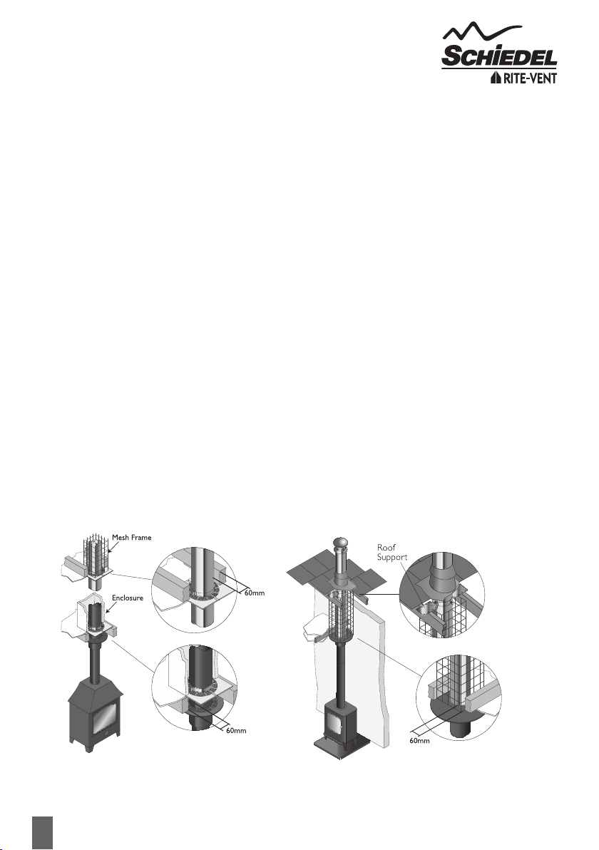
On bungalow applications where the chimney runs through either a combustible or non-combustible ceiling, an
unventilated bungalow re stop plate kit can be used. Please note that an unventilated support plate can not be
used above the ceiling in this case. The weight of the chimney should be supported using the roof support (see p.19).
Distance to combustibles must be respected within the ceiling space (see Fig. 2 below) and mesh frame should be used
within the loft space, which must be ventilated (see Fig. 2 below).
Enclosure/Shafts
With the exception of the room containing the appliance, where the chimney passes through any part of the
building, where there is a risk of accidental human contact, i.e a bedroom etc., or where there is a risk of contact with
combustible materials stored in a cupboard or in the roof-space, the chimney must be enclosed in an appropriate way
to meet Building Regulations. This can be achieved by boxing in the chimney in habitable rooms, or by the use of a
protective wire mesh frame in roof spaces etc. In all cases the minimum distance to any combustible material, including
loft insulation, must be respected according to the table on p.1, and any enclosure should be ventilated using the
appropriate ventilated re stops (see p.13).
Fig.1 Fig.2
Internal House
Combustible Floors
InternalBungalow(VentilatedLoftSpace)
Combustible and Non-Combustible Floors

9
Support Components
The weight of a chimney system is considerable and requires independent support. Minimal weight should be borne
by the appliance. The weight of the chimney can be supported from oor level by using a base support plate, or oor
support; from the wall by using wall support top plates together with side plates or cantilever brackets; or from rst
oor level by using a support plate and clamp xed to the oor/ceiling joists.
Wall brackets are non load bearing and provide lateral support only. Refer to the load bearing tables on page 33 for
full details of maximum loadings.
Where the ue is freestanding above the roof and its height exceeds 1.5m above the last support or above the roof, a
height of up to 3m can be achieved unsupported using the extended locking bands at the joint immediately below the
last support and on each pipe joint above the last support.
Alternatively guy wire brackets can be used at the 1.5m level and every 1.5m thereafter in conjunction with guy wires,
or rigid stays (provided by others).
Chimney Termination
For full information regarding to chimney termination, please refer to Annex M of BS EN 15287-1. As a guide please
refer to page 31 of these installation instructions.
Terminals
All terminals must be secured with the use of a locking band. On solid fuel appliances, an open termination is normally
recommended. However in certain conditions, rain caps or anti-downdraught terminals may be used.
Rain caps and anti-downdraught terminals are available in three versions, with anti-bird mesh, with spark guard, or
without mesh. Where a terminal with mesh is used, there is a risk of soot build up, and therefore regular cleaning is
required to avoid blockage, particularly when using oil or solid fuel.
10
INSTALLATION INSTRUCTIONS
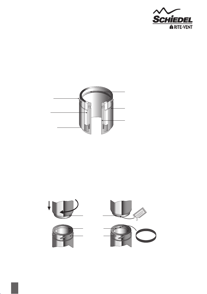
JointingSystem
All joints in the ICID Plus chimney range, which require a locking band, are made by means of a simple twist lock
jointing method. This is achieved by pushing together the male and female collars on each end of the main chimney
components and twisting the components through 1/6 of a turn to lock the collars into place.
It should be noted that the female collars on elbows and tees are not barbed in order to allow for these items to be
positioned according to requirements on site. In all cases the joints should be held securely in place using the locking
band, which is supplied with all components with a female collar.
StandardChimneySections(Pipes,TeesandElbows)
Before assembling chimney sections, loosen the locking band by lifting the clip. Push the interlocking collars together and
twist into position (see Fig.1). Position the locking band so that it grips both collars then fasten using the clip.
Note:-joints must NOT occur within oor or ceiling spaces.
All ue gas carrying components must be installed with the direction arrow on the product label pointing to termination
with the external male collar uppermost.
LockingBand(supplied with each component with a female collar)
A locking band must be tted to every joint in the system. The band is of stainless steel construction and is tted with
a quick release clip.
Fig.1
Without Lip Seal
ICID Plus for N rated
Negative Pressure
Applications
(i.e Stoves)
Fig.2
With Lip Seal
ICID Plus for P rated
Positive Pressure
Applications
(i.e Condensing Boilers)
Stainless Steel Outer Case
Male Collar
Stainless Steel Inner Liner
Insulation
Inward Bead
Female Collar
Male Collar
Lubricant
Female Lip Seal
Inward Bead
YELLOW PARAFFINWAX
DO NOT SWALLOW
Male Spigot
11
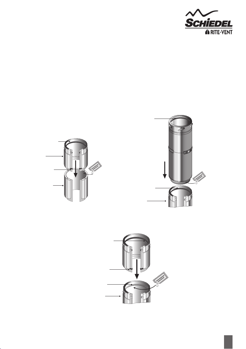
GasketKits
The standard single female lip seal kit is used to convert standard xed components with a male collar for use in
condensing applications. The female lip seal must be tted into the inward bead on the liner just below the male collar.
Lubricant should be applied to the outside of the protruding liner of the next component to be tted (see Fig.2)
A separate gasket kit with 2 gaskets (1 female and 1 male) and a sachet of lubricant is required for adjustable pipes.
The female lip seal, with the lip on the inside is tted, as per a standard component, into the inward bead as shown in
Fig.2. The second male lip seal with the lip on the outside of the ring is tted into the inward bead, which is situated in
the top half of the 2-piece adjustable pipe (see Fig.3) and at the bottom of the 1-piece adjustable pipe.
N.B Where a 1-piece adjustable pipe is used, then no female lip seal is required in the groove below the male collar
of the preceeding pipe.
Fig.3
2-PieceAdjustablePipe
1-PieceAdjustablePipe
On 2-Piece Adjustable Pipe a female lip seal is required on the preceeding standard pipe to ensure leakage performance
of the system. All lip seals to be added by installer.
On 1-Piece Adjustable Pipe no lip seal is required on preceeding standard pipe, as a male lip seal (once added) will ensure
leakage performance. All lip seals to be added by installer.
Female Lip Seal
(lip on inside)
Male Lip Seal
(lip on outside)
Lubricant
Top Half
Bottom Half
Female Lip Seal
(lip on inside)
Female Lip Seal
(lip on inside)
Lubricant
Preceeding
Standard Pipe
Lubricant
Female Lip Seal
(lip on inside)
Male Lip Seal
(lip on outside)
No Lip Seal
is required
Preceeding
Standard Pipe

12
AdaptorsfromPrimaPlus&PrimaSmoothtoICIDPlus
These components are used to convert from a single wall connecting ue pipe to the ICID Plus system chimney. The
protruding liner should be pushed down inside the female socket of the connecting ue pipe, with the male collar
pointing upwards.
AdaptortoFlex/TecnoFlexPlus
This component is used to convert from ICID Plus to Flex/TecnoFlex Plus.The Flex/TecnoFlex Plus is pushed down
inside the upstand on the adaptor, secured using self tapping screws and sealed with re cement and re rope to
provide a gas tight joint.
AdaptorfromICIDPlustoPrimaPlus
This component is manufactured with an ICID Plus female collar and a Prima Plus female socket, and is used where
there is a requirement to convert from ICID Plus to Prima Plus.The ICID Plus female collar should be attached to
the previous ICID Plus component and the joint secured using the locking band provided.
AdaptorfromICIDPlustoPrimaSmooth
This component is manufactured with an ICID Plus female collar and a Prima Smooth female socket, and is used where
there is a requirement to convert from ICID Plus to Prima Smooth. The ICID Plus female collar should be attached to
the previous ICID Plus component and the joint secured using the locking band provided.
StructuralLockingBand
The structural locking band, which is purchased separately, is used instead of a standard locking band in a situation
where extra structural support is required, for instance where the chimney height is >1.5m above the last support or
above the roof. It is also used to provide extra support in long horizontal runs. A maximum of 3m unsupported height
can be achieved by tting the structural locking band on the joint immediately below and on every joint above the last
support. Please see diagram on page 32.
StructuralLockingBandforBends
The structural locking band for Bend, which is purchased separately, is used instead of a standard locking band in a
situation where extra structural support is needed in an offset.
Appliance Connector
Male
Collar
Protuding
Liner
Appliance Connector
1.
2.
The protruding liner of these components should be pushed into the appliance
spigot with the male collar pointing upwards. The liner can be trimmed to suit
the depth of the appliance spigot.
On solid fuel appliances the appliance connector should be sealed to the
appliance with re rope and re cement or high temperature sealant to provide
a gas tight joint.
13
SW-DWStovePipeStarterSection
This component is used to connect from a vitreous enamel or stainless steel single
wall connecting ue pipe to ICID Plus. The protruding liner should be pushed
down inside the female socket of the connecting ue pipe and the joint sealed with
re cement or high temperature sealant to provide a gas tight joint.
Please note that when a single wall connecting ue pipe is used to connect to the
starter section, the joint between these two components must be a minimum of
425mm below the ceiling in accordance with BS EN 15287-1. This component
MUST only be tted to stove pipe and NOT directly to appliance.
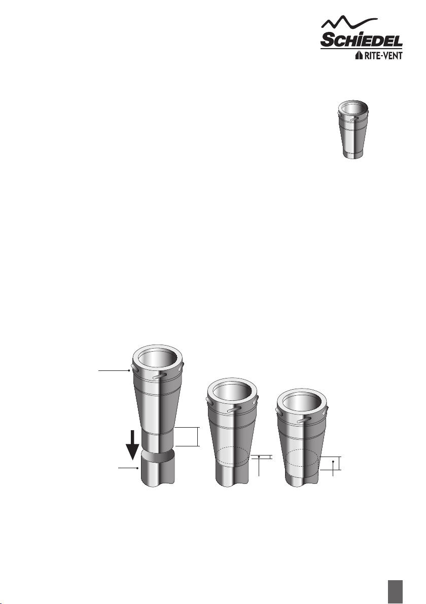
SW-DWAdjustableStarterSection
The protruding male spigot of the adaptor slides down inside the female socket of the Prima Smooth pipe and the
socket of the Prima Smooth pipe slides within the conical section of the starter adaptor, to a maximum length of 75mm
into the cone with a minimum of 15mm to ensure a secure connection.
This maximum length of 75mm will leave sufcient space within the adaptor to allow for thermal expansion of the
single wall pipe and also to allow for the connecting ue pipe to be removed without cutting, if the appliance has to
be moved for servicing.
This component MUST only be tted to stove pipe and NOT directly to appliance.
SW-DW
StovePipe
Starter Section
100
15 min 75 max
Prima Smooth
SW-DW
Adjustable
Starter Section
14
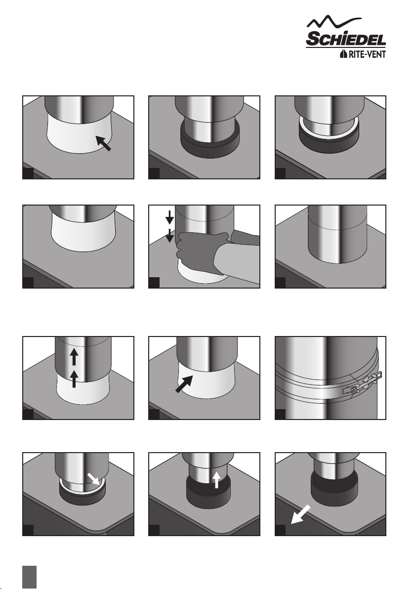
DoubleWallAdjustableStarterSection
Initial installation
Removal of stove for servicing
Remove loose strip of insulation and
keep to one side.
Slide adjustable case up inside the
outer wall of the chimney.
4.
1.
1.
2.
2.
3.
3.
Insulate liner using strip of insulation
with joint to rear. Width of insulation
can be trimmed to suit.
Insert male spigot of liner into the
appliance spigot.
Remove two loose insulation strips
and keep to one side.
Slide adjustable case down over the
insulation to cover the appliance spigot.
Finished installation.
Seal using the rope gasket, re
cement or similar.
Loosen the locking band on the liner
using the quick release clip (retain the
locking band to one side).
Break the re cement seal between
the appliance spigot and chimney liner.
4. 5. 6.
Slide the liner spigot up inside the
chimney until clear of appliance spigot.
Remove the appliance.
5. 6.
15
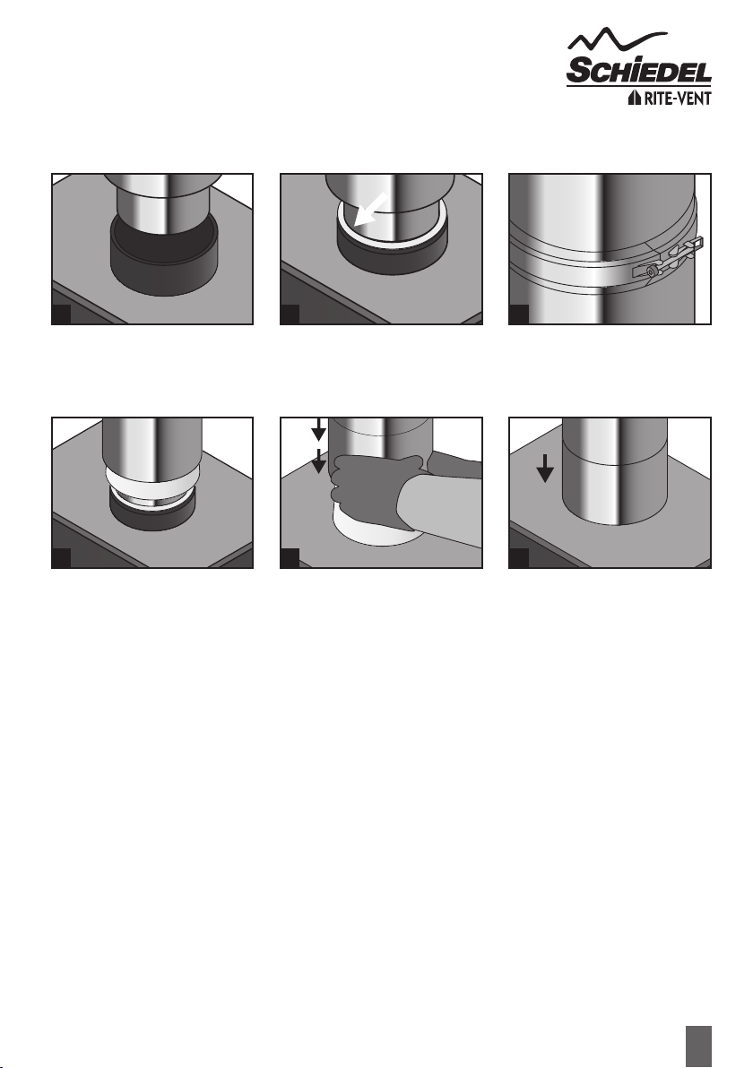
Re-installation of stove after servicing
Position stove spigot immediately
beneath liner spigot of chimney.
Position narrower strip of insulation
around the locking band with joint
to the rear.
1.
4.
2.
5. 6.
Slide liner spigot down inside the
appliance spigot and seal using the
re cement, rope gasket or similar.
Slide adjustable cover down 5mm
past insulation. Position nal insulation
around spigot with joint to the rear.
Slide locking band into place around
the joint on the liner. Now tighten the
bolt on the locking band around the
joint of the liner.
Slide adjustable case down over the
insulation to cover the appliance spigot.
3.

16
Anchor Plate
When commencing an installation with a re chest, or when extending an existing
brick or masonry chimney stack, an anchor plate must be used. The liner of the
Anchor Plate should be pushed into the opening of the re chest with the plate
resting on a bed of re cement. The plate should then be xed onto the concrete
slab by masonry screws tted through the pre-drilled holes in the plate. In the case
of a chimney extension, the liner of the anchor plate ts down inside the existing
chimney stack, or if TecnoFlex Plus liner has been used, inside the chimney as a liner,
use the anchor plate with screw type connections. Refer Flexible Liners installation
instructions for more details. The plate should then be then be xed to the top of
the existing chimney and sealed using re cement.
Inspection Pipe with Test Point
The inspection length is a component providing the facility for ue inspection
and cleaning, including a test point. It is installed as per a standard pipe section.
Two versions available for Dry and Wet systems. The removable inspection door
must be parallel with the front of the stove, or at least 3 x the internal diameter
from any combustible material (125mm I/D door must be at least 450mm from
combustible material).
AdjustablePipe/TelescopicPipes
They are used with standard components to achieve an exact length on site and
avoid on-site cutting of components.
1. Calculate the length required.
2. Remove insulation as required to achieve the correct length.
3. Fix the adjusted section to standard components using the locking band provided.
Please note that the adjustable pipe is non load bearing.
When used in a condensing or a positive pressure application, the relevant gasket
kits must be applied by the installer (gaskets purchased separately). Follow Page 11
for instructions on Gasket Kits.
Adjustable
Pipe
(50-230mm)
Telescopic
Pipe
a)215-310mm
b)350-570mm
Anchor Plate
Inspection Length
(DrySystems)
Effective
Length
302mm
Increaser
This component is used to increase from one diameter to the next diameter (e.g.) 125mm to 150mm. The component
is tted in the same way as a standard pipe length and should be secured with the locking band provided.
90˚Tee
Int Ø
Ext Ø
A
B
C
Int Ø
Ext Ø
90˚
90°TeeincludingDrainCap
This component may be used to connect from a connecting ue pipe to the
vertical system chimney at 90° or the branch may be used to locate a draft
stabiliser. It is installed as per a standard pipe section. Please note that there are
no barbs on the female collar in order to allow for the tee to be positioned at the
correct angle. It is supplied complete with a locking plug.
Int Ø
Ext Ø
A (mm)
B (mm)
C (mm)
100
150
282
150
120
200
256
394
195
170
125
180
301
154
133
150
200
329
162
142
180
235
354
176
160

17
Elbowsand90°InspectionElbows
For offset information on standard elbows, please refer to p.18
Please note that 90° Inspection bends may be incorporated into a connecting ue pipe arrangement on all fuels, please
refer to National Annex of BS EN 15387-1 for specic guidance re use on solid fuel applications.
In cases of top mounted stoves, a minimum vertical height of 600mm from the appliance is recommended prior to any
change of direction in the ue pipe.
On condensing appliances 87° bends must be used rather than 90° bends where required in order to ensure correct
run off of condensates.
93˚Tee including Drain Cap
This component must be used in place of a 90° tee to connect from a connecting
ue pipe to the vertical System Chimney on condensing systems to ensure that
condensate can drain down through the system to a drain point. This component
is installed as per a standard pipe section.
135°Tee including Drain Cap
There are 2 versions of the 135˚ tee available. The condensing version has a fully
welded liner, so please ensure, prior to installation on a condensing appliance, that
you have the fully welded version to hand.
This component may be used in combination with a 45° elbow to connect from a
connecting ue pipe to the vertical system chimney. It is installed as per a standard
pipe section and provides the least resistance to the ow of the ue gases. Please
note that there are no barbs on the female collar in order to allow for the tee to
be positioned at the correct angle. It is supplied complete with a drain plug.
135˚Tee
Int Ø
Ext Ø
A
B
C
Int Ø
Ext Ø
135˚
A
93˚Tee
Int Ø
Ext Ø
B
C
Int Ø
Ext Ø
93˚
Int Ø
Ext Ø
A (mm)
B (mm)
C (mm)
100
150
285
155
121
200
256
396
201
177
125
180
297
158
136
150
200
322
166
147
180
235
356
180
167
Int Ø
Ext Ø
A (mm)
B (mm)
C (mm)
100
150
325
254
254
200
256
444
351
351
125
180
336
259
259
150
200
365
283
283
180
235
414
326
326
18
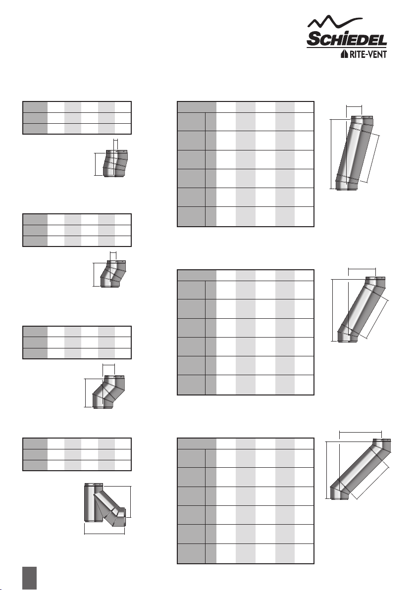
OFFSET DIMENSIONS
(made by assembling 2 bends)
Int Ø
A (mm)
B (mm)
125
232
31
100
228
30
150
234
31
180
234
31
200
238
31
Offsetsfor
15˚Bend
Int Ø
A (mm)
B (mm)
125
230
62
100
228
61
150
244
66
180
256
69
200
271
73
Offsetsfor
30˚Bend
Int Ø
A (mm)
B (mm)
125
254
105
100
256
106
150
268
111
180
295
122
200
309
128
Offsetsfor
45˚Bend
Int Ø
A (mm)
B (mm)
125
402
310
100
383
303
150
435
334
180
497
376
200
532
402
Offsetsfor
135˚Teeand45˚Bend
A
B
A
B
B
A
B
Effective Pipe
A
B
A
Effective Pipe
B
A
Effective Pipe
Offsetsfor15˚Bend
with Standard Pipe Length
Int Ø (mm)
1460 Eff A
Pipe B
960 Eff A
Pipe B
750 Eff A
Pipe B
460 Eff A
Pipe B
293 Eff A
Pipe B
160 Eff A
Pipe B
125
1642
408
1159
279
956
225
676
150
515
106
387
72
100
-
-
1155
278
952
224
672
149
511
106
383
71
150
1644
409
1161
279
958
225
678
150
517
107
388
72
180
1644
409
1161
279
958
225
678
150
517
107
388
72
200
1648
409
1165
280
962
225
682
150
521
107
392
73
Offsetsfor30˚Bend
with Standard Pipe Length
Int Ø (mm)
1460 Eff A
Pipe B
960 Eff A
Pipe B
750 Eff A
Pipe B
460 Eff A
Pipe B
293 Eff A
Pipe B
160 Eff A
Pipe B
125
1494
792
1061
542
879
437
628
292
483
208
368
142
100
-
-
1059
541
877
436
626
291
481
208
366
141
150
1509
796
1076
546
894
441
643
296
498
212
383
146
180
1520
799
1087
549
905
444
654
299
509
215
394
149
200
1535
803
1102
553
920
448
669
303
524
219
409
153
Offsetsfor45˚Bend
with Standard Pipe Length
Int Ø (mm)
1460 Eff A
Pipe B
960 Eff A
Pipe B
750 Eff A
Pipe B
460 Eff A
Pipe B
293 Eff A
Pipe B
160 Eff A
Pipe B
125
1287
1138
933
784
785
636
580
431
462
313
367
218
100
-
-
935
785
786
636
581
431
463
313
369
219
150
1300
1143
947
790
798
641
593
436
475
318
381
224
180
1328
1151
974
801
826
653
621
448
503
330
408
235
200
1341
1160
988
807
839
658
634
453
516
335
422
241
A
B

19
1.
2.
3.
4.
5.
Frame a four sided level square opening within the joists using timber stringers where necessary to allow for the
correct distance to combustibles from the outer wall of the chimney. This distance must be a minimum of 50mm on
Gas and Oil applications and 60mm for solid fuel applications (see Fig. 3 below).
Lower the chimney section through the opening in the oor, and secure to the next section of pipe.
Locate the two halves of the support plates around the chimney section, and secure to the joists using screws or bolts.
Remove the self-drilling screws which are fastened to the clamp band.Then fasten clamp band around the chimney
section and position on top of the plate. Tighten using the nuts and bolts provided.
Using the holes in the clamp band as a guide, fasten the three self-drilling screws to the outer case of the ICID Plus system.
Note:JointsmustNOToccurwithintheoororceilingjoists.
Ventilated Support Plate (Galvanised plate with S/S Band)
The support plate is used where the chimney passes through a combustible oor, and the weight
of the chimney has to be taken at oor level. The support plate must be rmly xed by using bolts
or screws. For load bearing Data refer to tables 1 and 2 on page 33.
Ventilated
Firestop Plate
Ventilated
Support Plate
FIRESTOP COMPONENTS
Fig.1 Fig.2 Fig.3
Ventilated Firestop Plate (1 & 2-Piece Round and 2-Piece Rectangular)
The ventilated re stop plates are used in combination with standard ICID Plus pipes where the
chimney passes through a combustible oor or ceiling.The outermost circle of ventilation slots gives
a distance to combustibles of 60mm. This measures the required distance for solid fuel applications.
For gas and oil applications a minimum of 50mm is required, which should be measured on site.The
re stop plate should be positioned around the chimney and fastened to the pre-cut plasterboard
or to the timber frame with nails or screws using the location holes provided (see Fig. 2 above).
MagneticFirestopCover(Optional)
Can be used in combination with 1-piece Ventilated Firestop Plate)
Non-Ventilated Bungalow Firestop
Installed as per a ventilated restop using the xing holes provided (see Fig.4 above). Distance to combustibles
must be respected - see p.8 for further info.
Support Plate with S/S Clamp Band (Non Combustible Floor)
The support plate is used where the chimney passes through a non combustible oor, and the weight of the chimney
has to be taken at oor level. The support plate must be rmly xed to the oor using bolts or screws provided by
others. For Load Bearing Data refer to table on page 33.
Fire stop Plate (Non Combustible Floor)
This re stop plate is used exclusively where the chimney passes through a non combustible oor.The two halves of
the plate are located around the chimney section and fastened to the oor using bolts or screws provided by others.
Non-Ventilated
Bungalow Firestop
Kit Installation In Situ

20
RetrotWallBand
AdjustableBackBracket(60-300mm)
Internal and External Application
The adjustable wall bracket is supplied in three parts, a ‘U’ shaped stainless steel
adjustable section, two bolts for xing the wall band to the back bracket and a
strengthening cross bracket.
WallBand(60mm)
Internal and External Application
The wall band is supplied in three parts, two stainless steel split bands which t
tightly around the outside of the chimney and a stainless steel back bracket.The
parts are joined together by means of the nuts and bolts provided.The use of the
item maintains a xed distance of 60mm from the outer casing of the chimney to
the wall or xing point.
Once the position of the support has been determined, secure the back bracket
to the wall with a method of xing to ensure adequate attachment and support.
The stainless steel split band is then positioned around the chimney section and
secured with the nuts and bolts provided to the back bracket.
The wall bracket provides lateral stability only, it is NOT load bearing and is to
be positioned at 3 metre centres.
1.
2.
3.
Once the position of the support has been determined, secure the U shaped
bracket to the wall with a method of xing to ensure adequate attachment
and support.
Determine the amount of extension required and secure the back bracket of
the wall band in place onto the adjustable section.
Fasten the strengthening cross bracket in place using the bolts provided.
With the back bracket in place, locate the rear portion of the band onto the
back bracket, the outer part of the band is then positioned around the chimney
section and secure with the nuts and bolts provided.
The adjustable wall band provides lateral stability only, it is NOT load bearing
and is to be positioned at 3 metre centres.
1.
2.
3.
4.
5.
Wall Band
(60mm)
Retrot
Wall Band
AdjustableBack
Bracket
(60-300mm)
Wall Band and
AdjustableBack
BracketAssembly
A
B
C
B
Int Ø
Ext Ø
A (mm)
B (mm)
C (mm)
125
180
131
112
25
100
150
131
83
25
150
200
148
132
25
180
235
185
162
25
200
256
202
186
25
Slide bracket down of chimney to the required position.
Once the position of the support has been determined, secure the back bracket
to the wall with a method of xing to ensure adequate attachment and support.
The wall bracket provides lateral stability only, it is NOT load bearing and is to
be positioned at 3 metre centres.
1.
2.
3.
60mm
60mm
Step 1 Step 2 In situ
Table of contents
Popular Fan manuals by other brands

Ebmpapst
Ebmpapst R2D250-AF10-12 operating instructions

System air
System air Sense SNX Installation,operation and maintenance instruction

Delta
Delta breez Smart SMT150-200 Installation and operating instructions

Ebmpapst
Ebmpapst S1G300-CA23-02 operating instructions

Holmes
Holmes Heater Fan owner's guide

Sulion
Sulion ALAN MOVE manual


