BMW E46 Convertible 2000 User manual

Initial Print Date: 02/2000 Revision Date: 03/21/00
Subject Page
Introduction ......................................................................................... 3
System Components
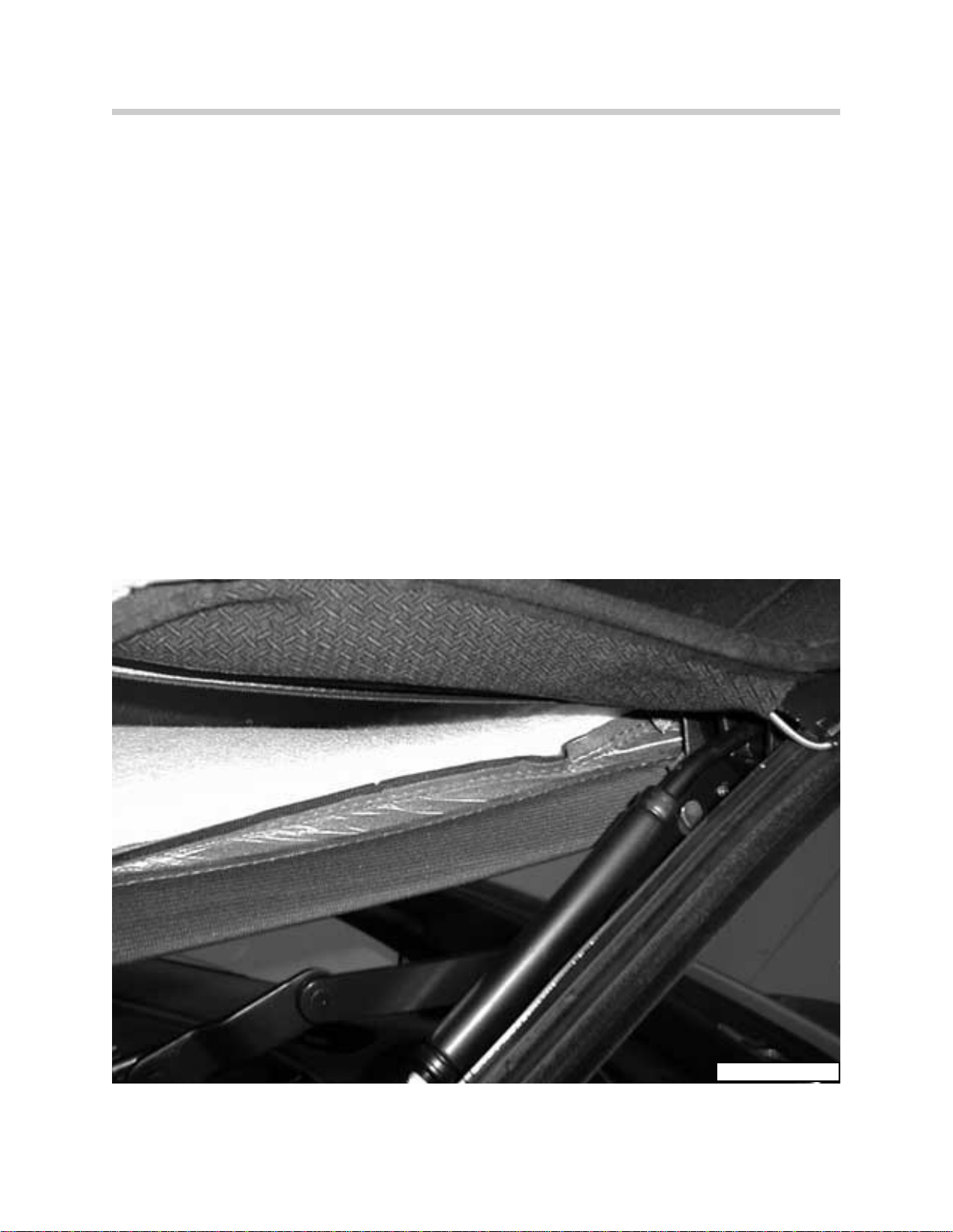
Top and Frame.................................................................................. 4
CVM ......................................................................................... 5
Hydraulic Unit.................................................................................... 6
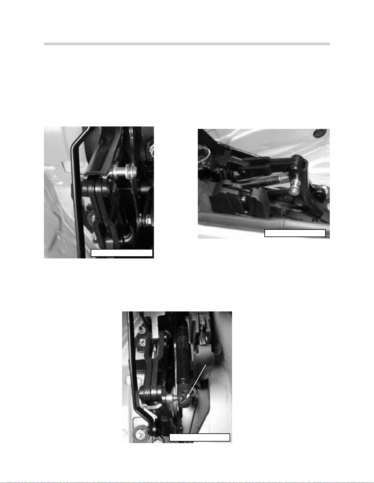
Hydraulic Cylinders............................................................................ 7
Hydraulic Solenoids........................................................................... 9
Storage Cover Motor......................................................................... 10
Windshield Frame Lock Assembly..................................................... 11
Top Switch ........................................................................................ 12
Hall Sensors...................................................................................... 13
Angle Hall Sensors ............................................................................ 19
Compartment Floor Micro Switch...................................................... 20
I P O ......................................................................................... 22
System Operation................................................................................... 23
Emergency Operation............................................................................. 28
Comfort Operation.................................................................................. 29
Diagnosis ......................................................................................... 30
Hard Top ......................................................................................... 33
Workshop Hints...................................................................................... 35
Roll Over Protection System................................................................... 40
Components...................................................................................... 42
Roll Over Sensor ............................................................................... 44
I P O ......................................................................................... 47
Table of Contents

2
E46iCCVM/ST039/3/21/00
BODY
Convertible Top
Model: E46 Convertible
Production Date: 01/00
Objectives of the Module:
After completing this module, you should be able to:
• Describe the lowering and raising sequence of the Convertible soft top in details.
• Name all the sensors and their functions that are used to open or close the soft top.
• Describe the information that is exchanged between the CVM ll and the GM V.
• Identify and describe electro-hydraulic components used in the Convertible top.
• Describe the information that is exchanged between the CVM II and the GM V.
• Describe the operation of the Storage Compartment Cover Lock Motor.
• Identify all the hall sensors, angle hall sensors and micro-switches used in the soft top.
• Explain all of the pre-conditions for Convertible soft top operation.
• Describe the wiring of the Hard Top Locks on the left and right.
• Diagnosis a Faulted CVM System.
• Describe the locking / unlocking procedure for the manual soft top.

3
E46iCCVM/ST039/3/21/00
INTRODUCTION
Purpose of the System:
The E46 Convertible-top is a fully automatic electro-hydraulic system that completely opens
and closes the soft-top using hydraulic cylinders and electric motors. It consist of the con-
vertible module (CVM II) which controls and monitors the complete operation of the system.
The CVM II interacts with the General Module which controls the operation the convertible-
top storage compartment cover and window operation when lowering or raising the soft-
top.
Convertible top features:
• Electro-hydraulic operation
• Comfort opening using FZV key or door lock cylinder
• Comfort closing using only the door lock cylinder (No anti-trap protection)
• Glass window
• Top operation monitored using hall sensors and angle hall sensors
CCoonnvveerrttiibblleeTToopp
MMoodduullee
HHyyddrraauulliiccUUnniitt
ww//SSoolleennooiiddss
SSttoorraaggeeCCoovveerrUUnnlloocckkMMoottoorr
TTooppaannddFFrraammee
SSoolleennooiiddVVaallvvee
BBlloocckk
GGeenneerraallMMoodduullee
TTooppSSwwiittcchh
ART-E46ICBODY

4
E46iCCVM/ST039/3/21/00
Components of the System:
Top and Frame
The top frame is similar to the E36iC with modifications for the adoption of the hydraulic
cylinders used for raising/lowering the top. The unlock motor and gear drive assemblies are
attached to the front of the top frame as on the E36iC.
The convertible top consists of three layers:
•TThheeoouutteerrllaayyeerris fabric with a non-replaceable glass rear window.
•AAmmiiddddlleefleece lliinneerris installed between the fabric and inner liner for sound and
weather insulating purposes.
•TThheeiinnnneerrlliinneerris similar to the E36iC and is attached to the top frame so that it
stretches tight when the top is closed.
OUTER FABRIC
INNER LINER
FLEECE LINER
ART-TOPLAYERS

5
E46iCCVM/ST039/3/21/00
Convertible-Top Module (CVM II)
The convertible-top module (CVM II) is installed in the left rear quarter panel behind the inte-
rior trim panel. It contains the processing, controlling and monitoring electronics for the
complete top operation. The CVM II communicates with the GM over the K-Bus for opera-
tion of the top storage cover and windows.
Operation of the hydraulic cylinders is controlled via final stages and solenoids mounted on
the hydraulic unit and top frame.
The CVM is fully diagnoseable and contains a fault memory for storage of monitored faults.
Diagnosis is carried out over the K-Bus with the DIS or MoDiC.
CVM II
61E46CVM0300
61E46CVM0400
CVM II

6
E46iCCVM/ST039/3/21/00
Hydraulic Unit
The hydraulic unit is mounted in the trunk on the left side behind the trim cover. It is mount-
ed on a rubber bushing and covered by sound insulation for noise reduction during pump
operation. The hydraulic unit consists of:
• Motor,
• Pump,
• Storage Cover Solenoid Valve/ Drain Solenoid Valve
• Reservoir.
• Temperature Sensor - hydraulic fluid
The hydraulic unit provides an operating pressure of up to 200 bar for the tops operation.
A temperature sensor on the hydraulic unit will signal the top module to cease operation if
the fluid temperature exceeds 950 C. Any function started will be completed before the sys-
tem is switched off. If the temperature exceeds 1050, the system is immediately switched
off and the emergency closing procedure will be required for closing the top.
When the temperature drops below 950, the operation of the top can be resumed.
Filling or checking the hydraulic fluid is only carried out when the top is lowered in the stor-
age compartment. The recommended fluid is “ARAL VITAMOL” PN 54 34 8 410 000 (Refer
to the repair manual for filling procedures)
54HYDRAULICPUMPE46050

7
E46iCCVM/ST039/3/21/00
Hydraulic Cylinders
Top Storage Compartment Cover
Two hydraulic cylinders are positioned on the left and right sides in the trunk for opening
and closing the top storage compartment cover. A Hall sensor is positioned on the left
cylinder to detect the full opened position of the cover.
Cylinder Removed Cylinder Installed
Tension Bow
Two hydraulic cylinders are positioned on the left and right sides of the tension bow, on the
top frame linkage for raising and lowering the bow. An angle hall sensor is installed on the
left tension bow linkage to detect the positioning of the bow. The hydraulic lines for the right
side tension bow cylinder are routed under the top fabric along the tension bow.
Hall Sensor
54E46CYLINDER1200 54E46CYLINDER1300
54E46CYLINDER0900
ART-KT5355

8
E46iCCVM/ST039/3/21/00
Main Pillar
Two hydraulic cylinders are positioned on the left and right sides of the top frame linkage
for raising and lowering the soft top frame. An angle hall sensor is used to detect the posi-
tioning of the main top linkage. The hydraulic lines for the right side main pillar cylinder are
routed under the top fabric along the tension bow.
Two gas filled piston struts are mounted on the top frame linkage, next to the hydraulic
cylinders, to dampen the raising and lowering of the top frame.
Gas Strut
54E46MAINPILLAR1000
54E46MAINPILLAR1100
54E46GASSTRUT0800

9
E46iCCVM/ST039/3/21/00
Hydraulic Solenoids
Two hydraulic solenoids are mounted on the hydraulic
unit:
• One solenoid valve controls the opening and closing
of the storage compartment cover
• The second solenoid valve is the drain solenoid for
relieving pressure in the hydraulic cylinders when the
key is switched off. The drain solenoid also holds sys-
tem pressure when the top switch is released during
operation.
Three hydraulic solenoids are mounted on the valve
block on the left side of the top frame.
• Solenoid valve V1 controls the operation of the main
pillar hydraulic cylinder.
• Solenoid valve V2 controls the tension bow
hydraulic cylinders for raising.
• Solenoid valve V3 controls the tension bow
hydraulic cylinders for lowering.
54E46HYDRAULICCONNECTOR0600
ARTSOLBLOCK

10
E46iCCVM/ST039/3/21/00
Storage Compartment Cover Lock Motor
The storage compartment cover lock motor is located on the drive shaft tunnel under the
rear seat. It consists of the motor with hall sensor, gear linkage assembly and two bowden
cables. Two locks are located on the right and left sides for locking the storage compart-
ment cover. The lock motor hall sensor detects the locked/unlocked position of the storage
cover.
During the soft top operation, when the tension bow is raised or when the top is in the stor-
age compartment, the CVM signals the GM, over the K-Bus, to unlock the storage com-
partment cover. The GM activates the lock motor and the motor turns 180 degrees to
unlock the cover latches. The motor always turns in the same direction to unlock/lock the
cover.
Once the motor has turned 180 degrees, the hall sensor input signal will cause the GM to
switch off the motor. At the same time, the GM will signal the CVM to continue top opera-
tion.
Hall Sensor
ART-KT-5380 ART-KT5382

11
E46iCCVM/ST039/3/21/00
Windshield Frame Lock Assembly
The windshield frame lock assembly consists of the top lock motor positioned in the cen-
ter of the top frame and two lock drive mechanisms positioned on the left and right sides
of the top frame. The operation of the lock motor and drive mechanisms is similar to the
E36 fully automatic top system. The drive mechanisms have been redesigned for smoother
operation, however they still are responsible for unlocking the top from the windshield and
raising the front of the top past the tension point. Flexible drive shafts are used activate
the lock assemblies and drive the tension linkage rods to raise the top past the tension
position.
Two hall sensor switches, located on the left lock drive assembly, are used to detect the
position of the top frame. One switch for the cowl lock signal and the second for the ten-
sion point position.
Right Lock Drive Left Lock Drive
ART-TOPLOCKMOTOR
ART-TOPLOCKRIGHT ARTOPLOCKLEFT

12
E46iCCVM/ST039/3/21/00
Convertible-Top Switch
The convertible-top switch assembly is located in the center console below the IHKA con-
trol panel. There are two push button switches, one for each direction of travel, that pro-
vide a ground input signal to the CVM for top operation.
Two LEDs are positioned in the center of the switch. The top LED will flash whenever the
top is in operation and not locked to the windshield frame or stored completely in the com-
partment. The lower LED will illuminate, if the top switch is pressed and the storage com-
partment floor is in the open position.
OPEN ROOF
CLOSE ROOF
54E46covswitch0100
ART-E46ICCVMTOP

13
E46iCCVM/ST039/3/21/00
Sensors and Switches
The hall sensors, angle hall sensors and micro switches provide feedback status to the
CVM and GM for soft top positioning and top sequencing during operation.
Hall sensors:
• Cowl Lock hall sensor
• Tension Point hall sensor
• Two Storage Compartment Cover Locks hall sensors
• Storage Compartment Cover hall sensor
• Storage Compartment Cover Motor hall sensor
• Hard Top Lock hall sensor
Angle Hall sensors:
• Tension Bow angle hall sensor - W1
• Main Pillar angle hall sensor - W2
Micro Switch
• Storage Compartment Floor micro switch
E46ICTOPUP.

14
E46iCCVM/ST039/3/21/00
Cowl Lock and Tension Point Hall Sensors
Two hall sensor switches are installed on the left side top lock drive assembly. Both sen-
sors receive power and ground from the CVM. One switch is the soft top locked to the
windshield frame input (cowl lock). The second switch is the top frame raised past the ten-
sion point input. As the slide assembly on the worm gear moves, it covers and uncovers
the hall sensors to cause the high/low switching to take place.
The cowl switch input provides a low signal when the top frame is unlocked from the wind-
shield (LED in the soft top switch will start to flash).
The tension point switch input provides a high signal when the top frame is raised past the
tension point.
Tension Point Sensor
Cowl Lock Sensor
ART-HALLSENSORSTOPLOCK
ART-E46ICCVMHALL2X

15
E46iCCVM/ST039/3/21/00
Storage Compartment Cover Lock Hall Sensors
There are two storage compartment cover lock hall sensor switches, one mounted on each
storage cover lock. The switches receive power and ground from the CVM. Each switch
input provides a high signal when the cover is unlocked and the cover is raised by the
hydraulic cylinders far enough to clear the latches.
When the storage cover is completely lowered by the hydraulic cylinders, the hall sensors
send a signal to the CVM. The CVM then signals the GM to relock the storage cover.
54E46COVERLOCK0700
ART-TPCVRLCK.CVM

16
E46iCCVM/ST039/3/21/00
Storage Compartment Cover Hall Sensor
The storage cover hall sensor switch is mounted on the left side storage cover hydraulic
cylinder in the trunk. It receives power and ground from the CVM. The switch provides a
high signal input when the storage cover is fully open.
The CVM uses the signal from the switch for top cover positioning and switching operation
during soft top lowering and raising. The CVM uses this input signal as a switching point
for activating the tension bow solenoid during top lowering or activation of the main pillar
solenoid during top raising.
Cover Hall Sensor
ART-E46ICCVMRAMROD
ART-KT-5355
TTrruunnkk--LLeeffttSSiiddee

17
E46iCCVM/ST039/3/21/00
Storage Compartment Cover Motor Hall Sensor
The storage cover motor hall sensor is mounted on the gear drive assembly of the motor.
It receives power and ground from the general module and provides a high signal input
when the motor has unlocked or locked the storage cover.
The GM uses this input to switch the unlock motor OFF. Additionally, the GM will electrical-
ly lock the trunk any time the storage cover is unlocked. The CVM receives a signal over
the K-bus of the unlock/lock status of the storage compartment cover.
Cover Motor Hall Sensor
E46ICGM12V.
ART-COVERLOCK

18
E46iCCVM/ST039/3/21/00
Hard Top Lock Hall Sensor
The hard top installed hall sensor is positioned on the left hard top lock. It receives power
and ground from the CVM and provides a high signal input when the hard top is installed
on the vehicle. The connector on the top of the lock is used as the power and ground sup-
ply for the rear window defroster of the hard top.
The CVM uses the input signal of the hall sensor to lock out soft top operation while the
hard top is installed.
54E46CVM1400
ART-MV563
HRDTPLCK.CVM

19
E46iCCVM/ST039/3/21/00
Angle Hall Sensor - Tension Bow
The angle sensor for the tension bow is mounted on the left side of the top linkage by the
tension bow hydraulic cylinder. The angle sensor receives power (5 volts) and ground from
the CVM. It provides a linear voltage signal input from approximately 0.5 to 3.5 volts as the
tension bow moves from a vertical to horizontal position.
The CVM uses the signal from the tension bow angle sensor to determine positioning of the
tension bow and switching operation during soft top lowering and raising.
61E46ANGLEHALLSENSOR0500
ART-E46ICTENBOW.

20
E46iCCVM/ST039/3/21/00
Angle Hall Sensor - Main Pillar
The angle sensor for the main pillar is mounted on the left side top linkage by the left main
pillar hydraulic cylinder. The angle sensor receives power (5 volts) and ground from the
CVM. It provides a linear voltage signal input from approximately 0.5 to 3.5 volts as the top
frame is lowered into and raised out of the storage compartment.
The CVM uses the input signal from the main pillar angle sensor for top frame positioning
Angle Sensor
Main Pillar
ART-MNPIHS
E46ICMAINPILL
Table of contents
Other BMW Automobile manuals

BMW
BMW SERIE 5 SPORT WAGON 2005 User manual

BMW
BMW M3 CONVERTIBLE 2003 User manual

BMW
BMW E60 User manual

BMW
BMW X2 2022 User manual

BMW
BMW M3 2003 User manual

BMW
BMW M Roadster 2006 Instruction Manual

BMW
BMW iX User manual

BMW
BMW 525I SEDAN User manual

BMW
BMW 2004 Z4 2.5i User manual

BMW
BMW 3 SERIES CONVERTIBLE - CATALOGUE User manual