BMW G01 User manual

Technical�training.
Product�information.
BMW�Service
G01�General�Vehicle�Electronics

General�information
Symbols�used
The�following�symbol�is�used�in�this�document�to�facilitate�better�comprehension�or�to�draw�attention
to�very�important�information:
Contains�important�safety�information�and�information�that�needs�to�be�observed�strictly�in�order�to
guarantee�the�smooth�operation�of�the�system.
Information�status�and�national-market�versions
BMW�Group�vehicles�meet�the�requirements�of�the�highest�safety�and�quality�standards.�Changes
in�requirements�for�environmental�protection,�customer�benefits�and�design�render�necessary
continuous�development�of�systems�and�components.�Consequently,�there�may�be�discrepancies
between�the�contents�of�this�document�and�the�vehicles�available�in�the�training�course.
This�document�basically�relates�to�the�European�version�of�left�hand�drive�vehicles.�Some�operating
elements�or�components�are�arranged�differently�in�right-hand�drive�vehicles�than�shown�in�the
graphics�in�this�document.�Further�differences�may�arise�as�the�result�of�the�equipment�specification�in
specific�markets�or�countries.
Additional�sources�of�information
Further�information�on�the�individual�topics�can�be�found�in�the�following:
• Owner's�Handbook
• Integrated�Service�Technical�Application.
Contact:�conceptinfo@bmw.de
©2017�BMW�AG,�Munich
Reprints�of�this�publication�or�its�parts�require�the�written�approval�of�BMW�AG,�Munich.
The�information�contained�in�this�document�forms�an�integral�part�of�the�BMW�Group�Technical
Qualification�and�is�intended�for�the�trainer�and�participants�in�the�seminar.�Refer�to�the�latest�relevant
information�systems�of�the�BMW�Group�for�any�changes/additions�to�the�technical�data.
Information�status:�June�2017
Technical�training.

G01�General�Vehicle�Electronics
Contents
1. Exterior�Lights....................................................................................................................................................................................................................................1
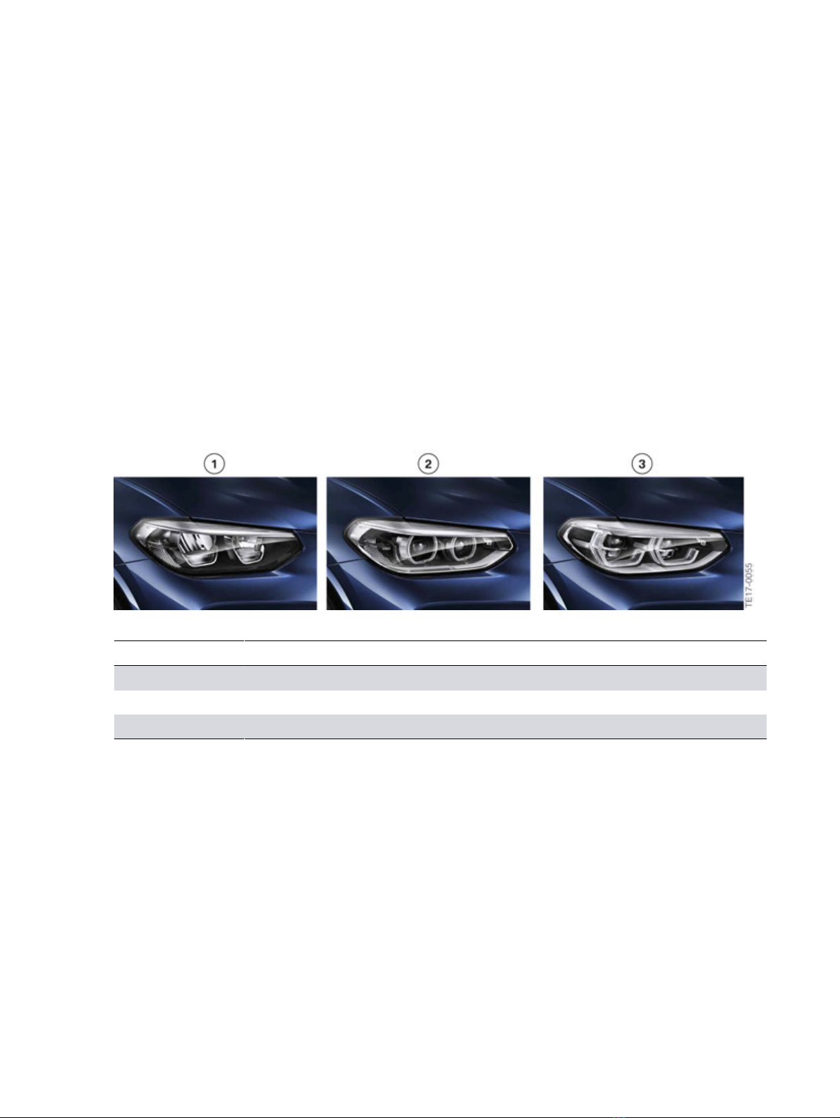
1.1. Versions................................................................................................................................................................................................................................. 1
1.2. Lighting,�front...............................................................................................................................................................................................................1
1.2.1. System�wiring�diagram�for�the�LED�headlight........................................................................ 2
1.2.2. LED�headlights.........................................................................................................................................................................4
1.2.3. LED�headlights�with�cornering�lights................................................................................................... 5
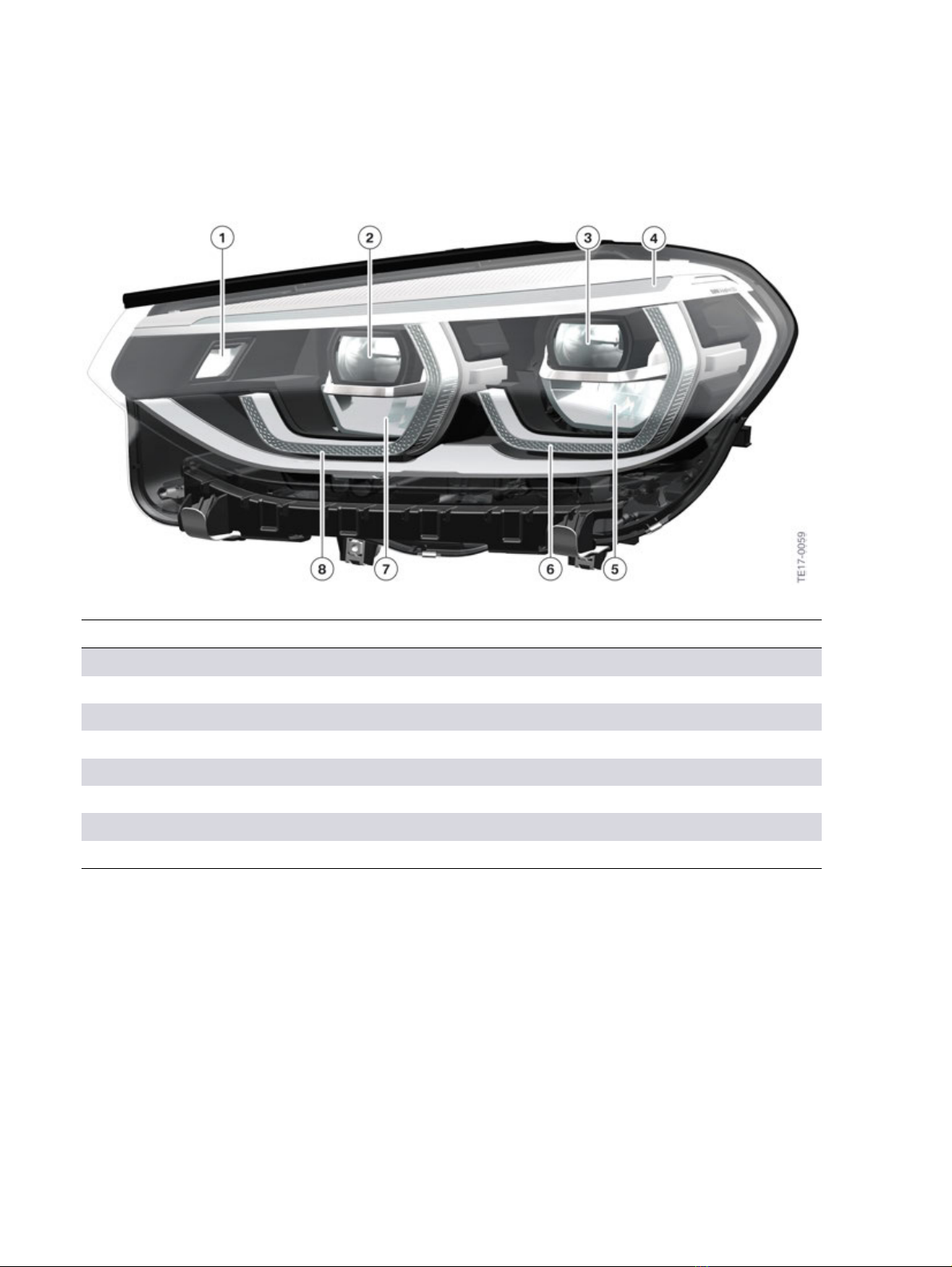
1.2.4. Adaptive�full�LED�headlights..............................................................................................................................6
1.3. Lighting,�rear................................................................................................................................................................................................................. 7
1.3.1. System�wiring�diagram................................................................................................................................................7
1.3.2. Rear�light............................................................................................................................................................................................8
1.4. Automatic�high�beams.................................................................................................................................................................................. 9
1.4.1. System�wiring�diagram............................................................................................................................................10
1.5. Entry�lights,�exterior...................................................................................................................................................................................... 10
1.5.1. System�wiring�diagram............................................................................................................................................11
1.5.2. Ground�lights.......................................................................................................................................................................... 12
1.5.3. Light�carpet............................................................................................................................................................................... 12
1.6. Trailer�lighting.......................................................................................................................................................................................................... 14
1.6.1. System�wiring�diagram............................................................................................................................................14
2. Interior�Lighting.......................................................................................................................................................................................................................... 16
2.1. Version................................................................................................................................................................................................................................ 16
2.2. Basic�interior�light.............................................................................................................................................................................................17
2.2.1. System�wiring�diagram............................................................................................................................................17
2.3. Ambient�lighting.................................................................................................................................................................................................. 19
2.3.1. System�wiring�diagram............................................................................................................................................20
3. Wash/Wipe�System...............................................................................................................................................................................................................23
3.1. System�wiring�diagram............................................................................................................................................................................. 23
4. Locking�and�Security�Functions..................................................................................................................................................................25
4.1. Comfort�Access................................................................................................................................................................................................... 25
4.1.1. System�wiring�diagram............................................................................................................................................25
4.2. Central�locking�system............................................................................................................................................................................. 27
4.2.1. System�wiring�diagram............................................................................................................................................27
4.2.2. Function.......................................................................................................................................................................................... 28
4.3. Automatic�operation�of�tailgate...................................................................................................................................................29
4.3.1. System�wiring�diagram............................................................................................................................................29
5. Alarm�System..................................................................................................................................................................................................................................31
5.1. System�wiring�diagram............................................................................................................................................................................. 31

G01�General�Vehicle�Electronics
Contents
6. Power�Windows...........................................................................................................................................................................................................................33
6.1. System�wiring�diagram............................................................................................................................................................................. 33
7. Panoramic�Sunroof............................................................................................................................................................................................................... 35
7.1. System�wiring�diagram............................................................................................................................................................................. 35
8. Steering�Column�Switch�Cluster.................................................................................................................................................................36
8.1. System�wiring�diagram............................................................................................................................................................................. 36
8.2. SZL........................................................................................................................................................................................................................................... 38
9. Door�Mirror...........................................................................................................................................................................................................................................39
9.1. Exterior�mirror�....................................................................................................................................................................................................... 39
9.1.1. System�wiring�diagram............................................................................................................................................39
10. Interior�Mirror..................................................................................................................................................................................................................................41
10.1. System�wiring�diagram............................................................................................................................................................................. 41
11. Seats................................................................................................................................................................................................................................................................ 42
11.1. Front�sport�seats................................................................................................................................................................................................42
11.1.1. Sport�seats�with�memory,�front,�driver's�side...................................................................... 42
11.1.2. Sport�seat,�front,�passenger's�side......................................................................................................44
11.2. Rear�seats......................................................................................................................................................................................................................46
11.2.1. Seat�heating,�rear�passenger�compartment..........................................................................46
12. Horn................................................................................................................................................................................................................................................................... 48
12.1. System�wiring�diagram............................................................................................................................................................................. 48

G01�General�Vehicle�Electronics
1.�Exterior�Lights
1
1.1.�Versions
The�following�exterior�light�versions�are�offered�for�the�G01:
• LED�headlights�(Standard�on�the�xDrive�30i)
• LED�headlights�with�cornering�lights�(OE�5A4�optional�on�xDrive�30i)
• Adaptive�full�LED�headlights�(Standard�on�the�M40i)�(optional�OE�552�on�xDrive�30i).
The�low-beam�headlight�is�automatically�switched�on�when�the�system�recognizes�that�it�is�dark,�even
with�the�light�switch�in�position�0�and�when�driving�readiness�is�activated�(country-specific).
1.2.�Lighting,�front
Headlight�versions�for�the�G01:
Headlight�versions
Index Explanation
1 LED�headlights
2 LED�headlights�with�cornering�lights
3 Adaptive�full�LED�headlights

G01�General�Vehicle�Electronics
1.�Exterior�Lights
2
1.2.1.�System�wiring�diagram�for�the�LED�headlight
Front�exterior�lights,�LED�headlights

G01�General�Vehicle�Electronics
1.�Exterior�Lights
3
Index Explanation
1 Left�fog�light
2 Right�fog�light
3 Left�headlight�with�Frontal�Light�Electronics�Left�(FLEL)
4 Right�headlight�with�Frontal�Light�Electronics�Right�(FLER)
5 Fuses�in�the�power�distribution�box,�front�right
6 Body�Domain�Controller�(BDC)
7 Fuse�in�the�Body�Domain�Controller
8 Turn�indicator�in�exterior�mirror,�right
9 CAN�terminator
10 Fuse�for�rear�right�power�distribution�box
11 Fuse�in�the�power�distribution�box,�battery
12 Ride-height�sensor,�rear�left
13 Turn�indicator�in�exterior�mirror,�left
14 Light�switch
15 Steering�column�switch�cluster�(SZL)
16 Hazard�warning�switch/Intelligent�Safety�button
17 Rain-light-solar-condensation�sensor�(RLSBS)
18 Ride�height�sensor,�front�left
The�system�wiring�diagram�shows�the�basic�version.�Depending�on�the�headlight�version,�different
components�are�installed�in�the�corresponding�headlight.
The�wiring�diagram�shows�the�turn�indicator�and�the�high�beam�headlight�with�bulbs.�Depending�on
the�headlight�version,�the�turn�indicator�is�designed�either�with�LED�technology�or�a�bulb.�A�halogen
bulb�or�LED�is�used�for�the�high�beam.

G01�General�Vehicle�Electronics
1.�Exterior�Lights
4
1.2.2.�LED�headlights
LED�headlights
Index Explanation
1 High-beam�headlight
2 Low-beam�headlight
3 Turn�indicator
4 Side�lights�and�daytime�driving�lights
5 Side�lights�and�daytime�driving�lights
In�the�LED�headlight,�the�low-beam�headlight�is�located�in�the�outer�reflector.
A�halogen�bulb�is�used�for�the�high�beam�in�the�inner�reflector.
A�bulb�is�used�for�the�turn�indicator.

G01�General�Vehicle�Electronics
1.�Exterior�Lights
5
1.2.3.�LED�headlights�with�cornering�lights
Adaptive�cornering�light
Index Explanation
1 Cornering�light
2 Low-beam�headlight/High-beam�headlight
3 Turn�indicator
4 Side�lights�and�daytime�driving�lights
5 Side�lights�and�daytime�driving�lights
On�the�Adaptive�Headlight�the�low-beam�headlight�and�high�beam�are�in�the�same�reflector.
A�bulb�is�used�for�the�turn�indicator.

G01�General�Vehicle�Electronics
1.�Exterior�Lights
6
1.2.4.�Adaptive�full�LED�headlights
Adaptive�LED�Headlights
Index Explanation
1 Cornering�light
2 Low-beam�headlight
3 Low-beam�headlight
4 Turn�indicator
5 High-beam�headlight
6 Side�lights�and�daytime�driving�lights
7 High-beam�headlight
8 Side�lights�and�daytime�driving�lights

G01�General�Vehicle�Electronics
1.�Exterior�Lights
7
1.3.�Lighting,�rear
1.3.1.�System�wiring�diagram
Rear�exterior�lights

G01�General�Vehicle�Electronics
1.�Exterior�Lights
8
Index Explanation
1 Digital�Motor�Electronics�(DME)
2 Electronic�transmission�control�(EGS)
3 Fuses�in�the�power�distribution�box,�front�right
4 Body�Domain�Controller�(BDC)
5 Fuse�in�the�Body�Domain�Controller
6 Rear�light�cluster,�right�outer
7 Rear�light�cluster,�right�inner
8 License-plate�light,�right
9 License-plate�light,�left
10 Rear�light�cluster,�left�inner
11 Rear�light�cluster,�left�outer
12 Additional�brake�light
13 Interference�suppression�filter
14 Light�switch
15 Hazard�warning�switch/Intelligent�Safety�button
16 Steering�column�switch�cluster�(SZL)
17 Rain-light-solar-condensation�sensor�(RLSBS)
18 Brake�light�switch
The�system�wiring�diagram�shows�the�basic�version�with�bulbs�and�LEDs�for�the�tail�light.
In�the�High�version,�all�light�functions�are�realized�with�LED�technology.
1.3.2.�Rear�light
On�the�G01,�2�different�rear�lights�are�installed�depending�on�the�headlight�version.
The�Basic�rear�light�is�used�on�vehicles�with�the�following�equipment:
• LED�headlights
• LED�headlights�with�cornering�lights.
The�High�rear�light�is�used�on�vehicles�with�the�following�equipment:
• Adaptive�full�LED�headlights.
In�the�Basic�rear�light,�only�the�tail�light�is�in�LED�technology.�Bulbs�are�used�for�all�other�light
functions.
In�the�High�rear�light,�all�light�functions�are�in�LED�technology.

G01�General�Vehicle�Electronics
1.�Exterior�Lights
9
Rear�light
Index Explanation
A High�rear�light
B Rear�light�(basic�version)
1 Brake�light
2 Turn�indicator
3 Tail�light
4 Reversing�light
1.4.�Automatic�high�beams
High-beam�assistant
On�vehicles�with�camera-based�driver�assistance�systems�KAFAS,�the�function�of�the�automatic�high-
beams�is�performed�by�KAFAS.
On�vehicles�without�camera-based�driver�assistance�systems�KAFAS,�the�automatic�high-beam�is
integrated�in�the�interior�mirror.
Automatic�high�beams�are�standard�on�the�M40i�and�optional�on�the�xDrive�30i�(OE�5AC).

G01�General�Vehicle�Electronics
1.�Exterior�Lights
10
1.4.1.�System�wiring�diagram
Automatic�high-beams�without�KAFAS
Index Explanation
1 Automatic�high-beams�(FLA)
2 Fuse�for�front�right�power�distribution�box
3 Body�Domain�Controller�(BDC)
4 Fuse�in�the�Body�Domain�Controller
5 Light�switch
6 Steering�column�switch�cluster�(SZL)
7 Instrument�cluster�(KOMBI)
1.5.�Entry�lights,�exterior
The�exterior�light�staging�for�the�G01�may�include�the�following�items,�depending�on�the�optional
equipment:
• Ground�lights
• Light�carpet

G01�General�Vehicle�Electronics
1.�Exterior�Lights
11
1.5.1.�System�wiring�diagram
Entry�lights,�exterior

G01�General�Vehicle�Electronics
1.�Exterior�Lights
12
Index Explanation
1 Body�Domain�Controller�(BDC)
2 Light�carpet,�right
3 Door�entry�light�in�front�passenger�door
4 Door�entry�light�in�the�rear�passenger’s�side�door
5 Door�entry�light�in�the�rear�driver's�side�door
6 Door�entry�light�in�the�driver's�door
7 Light�carpet,�left
1.5.2.�Ground�lights
The�ground�lighting�is�integrated�in�the�corresponding�door�modules.�The�LEDs�of�the�ground�lighting
are�activated�by�the�Body�Domain�Controller�(BDC).
1.5.3.�Light�carpet
The�light�source�is�integrated�in�the�side�sill�so�that�it�is�invisible�for�the�customer.�The�function�can�be
realized�in�a�very�small�installation�space�through�the�use�of�a�multi-lens�array�system.�A�very�flat�angle
of�radiation�is�also�possible.�The�graphic�is�superposed�several�times�by�the�multi-lens�array�system
and�is�therefore�insensitive�to�dirt�contamination.�The�light�carpet�is�activated�by�the�Body�Domain
Controller�(BDC).
LEDs�in�the�side�sill

G01�General�Vehicle�Electronics
1.�Exterior�Lights
13
Light�carpet
Light�carpet

G01�General�Vehicle�Electronics
1.�Exterior�Lights
14
1.6.�Trailer�lighting
1.6.1.�System�wiring�diagram
Trailer�lighting

G01�General�Vehicle�Electronics
1.�Exterior�Lights
15
Index Explanation
1 Instrument�cluster�(KOMBI)
2 Body�Domain�Controller�(BDC)
3 Exterior�mirror,�front�passenger�side
4 CAN�terminator
5 Power�distribution�box,�rear
6 Trailer�module�(AHM)
7 Additional�brake�light
8 Interference�suppression�filter
Vehicles�with�a�trailer�coupling�are�equipped�with�a�trailer�module�AHM.�The�trailer�module�is
responsible�for�the�following�functions:
• Light�control�for�trailer
• Monitoring�the�trailer�power�circuits

G01�General�Vehicle�Electronics
2.�Interior�Lighting
16
2.1.�Version
Depending�on�the�optional�equipment�selected�the�G01�has�different�light�elements�for�the�interior
lighting.
Table of contents
Other BMW Automobile manuals

BMW
BMW M4 User manual

BMW
BMW 3 SERIES CONVERTIBLE - CATALOGUE User manual

BMW
BMW 528e Programming manual

BMW
BMW M6 Convertible User manual

BMW
BMW ActiveHybrid 5 User manual

BMW
BMW ACTIVE HYBRID 7 BROCHURE 2010 User manual

BMW
BMW 325i Convertible 1988 Programming manual

BMW
BMW 735 User guide

BMW
BMW SERIE 3 CONVERTIBLE 2000 User manual

BMW
BMW M3 SEDAN User manual