BMW 745i Setup guide

BMW 745i
TEST AND REPAIR INSTR
UCTIONS
FOR
SUPERCHARGED
ENGINE
Bayerische
Mataren
Werke
AG
Munich
Service
Division

.-
INTRODUCTION
These testing and repalrmg instructions
will
supplement
the
information
in
the
728
i
through
735
i
Repair Manual.
This brochure contains
the
most
important
test and repair jobs
for
the
BMW
745
i Turbo.
The
728
i
through
735
i Repair Manual
will
have a supplement later
to
include
the
information
con·
tained in this brochure.
The brochure should be
used
by
shop foremen and mechanics
to
supplement
the
practical and theo·
retical knowledge
they
have acquired at
our
service training school.
Specifications are provided at
the
end
of
the
brochure and apply
to
standard models
which
have
not
been involved in
an
accident and have
not
been
modified
since leaving
the
factory.
The special
tools
required
for
proper repair
work
are listed
in
our
microfilmed
Special
Tool
Catalog
No.
01
999
699
422
.
Their
application
is
illustrated along
with
the
job
text.
Each
job
text
always describes
the
removal procedures. There are appropriate installation notes,
if
installation cannot be completed
in
reverse sequence.
BAYERISCHE
MOTOREN
WERKE
AG
SERVICE
DIVISION

1. DESCRIPTION
1.1 General Information
The
power
output
of
an engine
is
governed by
three
factors, namely pressure, speed and
the
displace-
ment.
Applied formula:
p::::::
p x n x VH P
;::
Output
************
p
;::
Pressure
n
;::
Speed
VH
;::
Displacement
The
power
output
of
a specific engine can be increased by raising
the
speed
or
pressure. Since
the
speed
is
limited by
the
occurence
of
inertia force, it
is
preferred
to
keep pressure
"p"
as high as pos-
sible.
Pressure
"p"
depends on
the
compression ratio and volumetric efficiency (cylinder charge). Since an
increase
in
compression ratio will only
produce
a relatively small rise
in
pressure, it
is
obviously
better
to
optimize
the
cylinder charge. This can be accomplished by precompression
of
the
intake air.
The
cylinder charged will be increased even more by also cooling
the
precompressed air.
The
precompres-
sion
of
intake air
is
known
as supercharging. An engine can be supercharged with a compressor
or
an
exhaust gas turbocharger.
The
application
of
a compressor
is
disadvantageous since operation of
the
compressor uses some
of
the
engine's power
output.
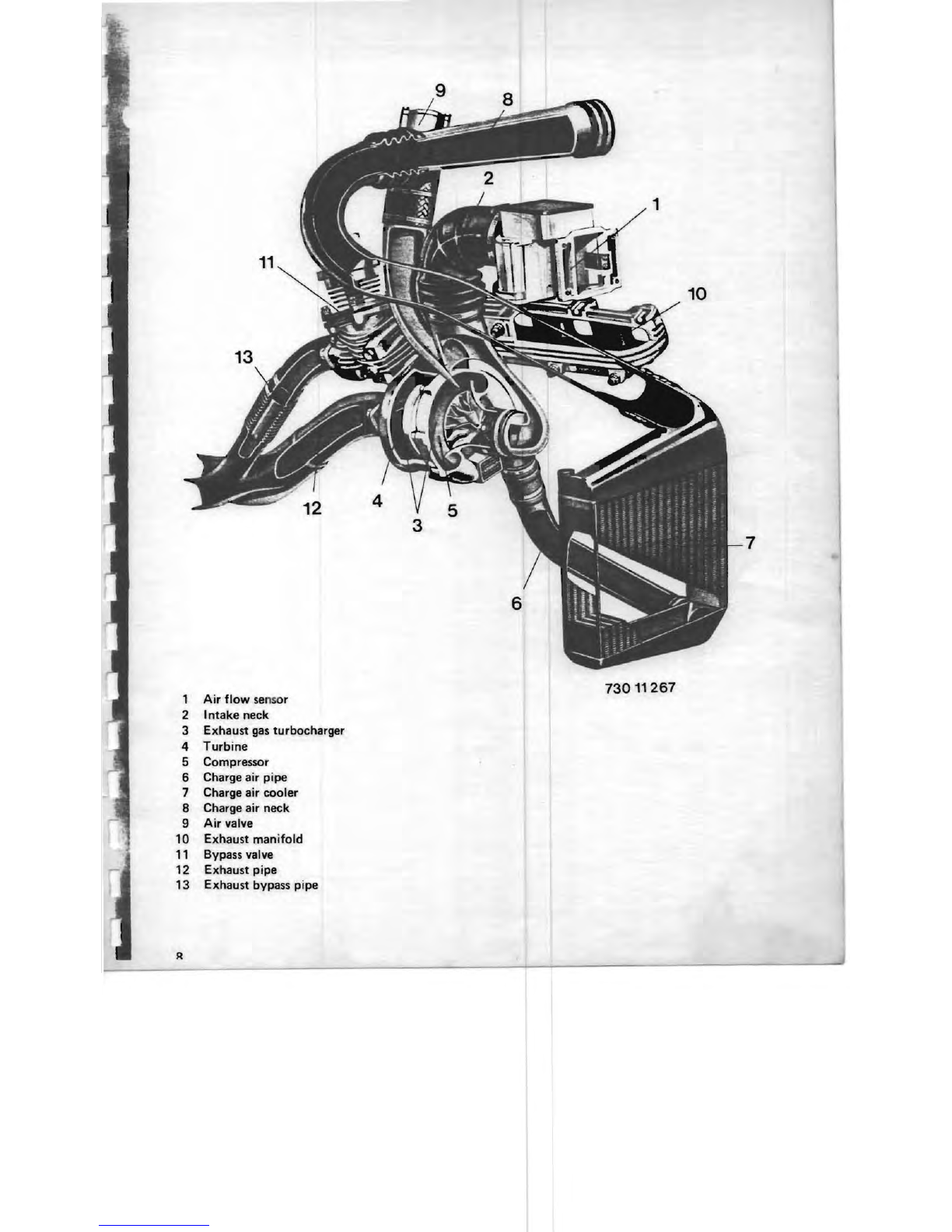
Supercharging with an
exhaust
gas turbocharger,
on
the
other
hand, uses
mecllanical energy converted from
part
of
the
energy contained
in
exhaust
gases
to
drive
the
compres-
sor.
5

A 3.2
liter
SIX
cylinder
unit
with
continuous
fuel
Injection
(
LJetronlc)
IS
the
lJaSIS
for
the
supercharged
engine version.
1
Air
flow
sensor
Measures
flow
of
intake
air
2 Exhaust
gas
turbocharger
Consists
of
a
turbine,
which
is
driven
by
the
exhaust
gas
flow
, and a compressor,
which
is
connec-
ted
with
the
turbine.
3 Charge air
cooler
Cools the charged
air
4 Bypass valve
For
exhaust end
control
of
the
charge pressure
5
Air
valve
For
control
of
charge pressure
while
coasting
6
Exhaust
manifold
In
two-piece
version
7
Crankshaft
Seven bearings,
drop
forged,
12
counterweights
8
Cylinder
9
Cylinder
head
Light
alloy
with
adequate
combustion
chamber
enlargement
~
=
7:1
10 Camshaft
Running
on
four
bearings
in
cylinder
head
11
Electromagnetic
fuel
injectors
12
Vibration
damper
6

I
r ,
11
1
6
~~-8
~---12
~-----3
73000
117
7

1
2
Air
flow
se
nsor
Intake
neck
3 Exhaust
gas
turbocharger
4
Turbine
5
6
7
8
9
10
11
12
13
Compressor
Charge air pipe
Charge air cooler
Charge air neck
Air
valve
Exhaust
manifold
Bypass valve
Exhaust pipe
Exhaust bypass pipe
7
73011267

.,.......
Layout
Drawing
1
2
3
4
5
6
7
8
9
10
11
air
cleaner
air
flow
sensor
compressor
2
exhaust
gas
turbocharger
turbine
charge
air
coole
r
air valve
bypass
valve
exhaust
manifold
intake
manifold
control
line
3 4 5
10
73011274
The
turbine
is
propelled
by
the
velocity
of
exhaust
gas flow.
Since
the
turbine
and
compressor
are
con
nected
with
each
other,
the
compressor
takes
in air.
The
intake
air,
which
enters
the
compressor
via
the
air
cleaner
and
air
flow
sensor,
is
passed
on
to
the
charge
air
cooler
after
supercharging.
The
charge
air
temperature
is
reduced
here
and
then
the
charge
air
continues
via
the
charge
air necks,
the
opened
throttle
housing
and
the
intake
manifold
to
the
separate
cylinders.
The
charge
pressure
must
not
exceed
approx.
0.7
bar
(10
psi), so
that
it
must
be
controlled.
This
is
ac·
complished
with
the
help
of
an
exhaust
gas
bypass
valve.
The
compressor
and
bypass
valve
are
connec
-
ted
with
each
other
via a
control
line.
The
bypass
valve
wi1l
open
when
charge
pressure
is
excessive, so
that
part
of
the
exhaust
gases will
flow
into
the
bypass
pipe
of
the
exhaust
system.
This
reduces
the
pressure
on
the
turbine
and
therefore
also
the
charge
pressure.
Since
the
compressor
wiU still be
running
when
closing
the
throttle,
there
could
be
unwanted
backpres·
sure
in
the
charge
air
neck.
This
is
avoided
by
applying
an air valve. A
vacuum
hose
connects
the
air
valve
with
the
intake
manifold.
The
air valve will
be
opened
by
the
vacuum
produced
when
the
throttle
is
closed
and
the
charge
air will flow
through
the
bypass
line
to
the
Intake
side
of
the
compressor.
9
J

1.3.2 Bypass Valve
6-=======i~
1 Valve
2 Housing
3 Diaphragm springs
4 Spring
5 Control line conn.
6 Heat
sh
ields
-.....-----2
~~;;;;;::::::J
-----------------1
730" 268
I
11

~
I
I
1.3.3 Charge
Air
Cooler
,
~
)
~t?o
73013088
The air temperature
rises
considerably when supercharging
the
intake air in
the
compressor
of
the
ex-
haust
gas
turbocharger.
The high temperature
of
the air
has
two
disadvantages.
a)
Heating
the
air
will
reduce its density and consequently the
volumetric
efficiency
(cylinder charge).
b) The combustion temperature
will
rise and therefore also the thermal engine loads.
These disadvantages can be avoided'
by
applying a charge air cooler.
12

2.
IMPORTANT
INFORMATION
2.1
Inspections
The cylinder head bolts must
not
be
retightened during
the
1,000
km
(600 mile)
and
7,500 km (5,000
mile) inspections, since
they
had been
torque
angle (250
,±
50) tightened in
the
plant after
the
engine
test run. Refer
to
page
82
for
further
information.
The exhaust manifold
mounting
nuts must be,retightened during
the
1st inspection (1,000
km
or
600
miles). The exhaust
manifold
nuts do
not
have
to
be
tightened during all
other
inspections on
the
super-
charged engine.
Procedures:
Pull
off
multiple
pin
plug (1).
Loosen hose clamp (2) and
pull
intake hose
off
of
air
flow
sensor.
INSTALLAT
'ION -
IMPORTANT!
Make sure in-
take hose and hose clamp are positioned correctly.
Remove intake neck.
INSTALLATION
-
IMPORTANT!
Make sure hose
clamps
and
hoses
are positioned correctly.
Remove heat shield.
Detach
control
line at
top
.
IMPORTANT!
Hold adapter
with
a wrench when
detaching and attaching line.
If
adapter
is
or
becomes loose, reinstall
it
with
Loc-
tite
No. 270.
Attach
control
line
that
there
is
no
tension.
13

14
Detach heat shield.
Tighten
nuts
to
15
Nm
(11 ft. Ibs.).
NOTE:
Use
torque
wrench
00
2
050
in
conjunction
with
special ring wrench
11
6 030.
Set
the
torque
wrench
to
12
Nm
(9 ft. Ibs.) due
to
the
length
of
the
special ring wrench.
Tightening
nut
covered
by
the
hydraulic
unit:
Unscrew nuts on
hydraulic
unit.
INSTALLATION:
Tighten nuts
to
22
...
25
Nm
(16
...
18 ft. Ibs.).
Press
hydraulic
unit
off
of
exhaust
manifold
with
a screwdriver and
tighten
the
nut.
IMPORTANT!
Apply
tip
of
screwdriver
on
exhaust
manifold
to
prevent damage
to
seal
of
hydraulic
unit.

2.2
Hoses
and
Lines
All air-carrying
connections
as well as
vacuum
and
pressure
lines
must
be
mounted
according
to
the
spe-
cifications.
73013086
73013087
WRONG
CORRECT
Only
use specified
connecting
hoses
and
lines!
Absolute
cleanliness
is
essential
when
detaching
any
air-carrying
part
(plug openings).
If
dirt
is
allowed
to
enter
the
exhaust
gas
turbocharger,
the
blades will
be
destroyed
by
the
very high
speed
when
operated.
After
assembling
components
in
the
repair
sector
it will be necessary
to
check
all air-carrying connec-
tions
as well as
vacuum
and
pressure lines
for
leaks!
LEAKY
OR
DISCONNECTED HOSES CAN CAUSE ENGINE DAMAGE
OR
A
DROP
IN
POWER
OUTPUT!
2.3
Ignition Cables
and
Caps
The
ignition cables
and
caps
employed
on
the
supercharged engine
are
made
of
a high
temperature
resistant materiall.
Only
the
specified ignition cables
and
caps
may
be used
for
the
supercharged engine!
2.4
Nuts
and
80
1
lts
Since very high
temperatures
will
be
experienced
at
the
exhaust
end,
special high
temperature
resistant
nuts
from
the
aircraft
construction
industry
are
apphed
for
the
installation
of
attachments.
These
are
self-locking, twelve-sided
nuts
with
a collar
for
temperatures
up
to
650
0 C
(1200
0 F) according
to
Avia-
tion
Standard
LN
9339.
Only
these
nuts
may
be
used
for
the
exhaust
manifold,
bypass valve as well as
exhaust
assembly
to
the
manifold
or
bypass valve!
Tighten
nuts
to
the
specified
torque!
15

3. TESTS
1211004
CHECKING
AND
ADJUSTING
IGNI-
TION
TIMING
AND
DWELL
ANGLE
Connect BMW service test
unit
or
BMW digital test-
er according
to
the
operating instructions_
I
IMPORTANT!
Al
lways stop engine and
turn
off
ignition
prior
to
any
work
on a breakerless,
tranSIS-
tor,
coil
ignition
system -danger!
a)
Dwell Angle:
The dwell angle
is
given
by
design and can't
be
al
-
tered. Dwell angle at:
1500
rpm = 32 ... 520 on
distributor
shaft and at
_________
....:7...::3:.:::0~1~2..:::0~27
4500
rpm = 47 ... 570
on
distributor
shaft.
Check
dwell
angle.
b)
Ignition
Timing:
The
ignition
timing
must be adjusted very accurate-
lyon
a supercharged engine.
An
inaccurately
ad-
justed
ignition
timing
could
cause
engine damage.
Pull
off
hoses
(1) and (2).
INSTALLATION:
Hose (1) must
be
mounted
with
a hose clamp. Make sure
fit
is
correct!
Ignition
timing
at 2200 rpm: 350 before
TDC
Correcting:
Loosen
the
distributor
mounting
bolt
and adjust
the
ignition
timing
by
turning
the
distributor.
+ = advanced
- = retarded
17

18
Connect vacuum pump
61
6 030
on
the
"retarded
box".
The aforementioned ignition
timing
must
be
mov-
ed
10
±.
2!l
toward
"retarded"
with
a vacuum
of
0.3 bar (4.2 psi).

,....
-.
73013
1300054
CHECKING
AND
ADJUSTING
EN
·
GINE
IDLE
SPEED
AND
FUEL/AIR
MIXTURE
a)
Engine Idle Speed:
Requirements:
Ignition
timing
correct.
Engine at operating' temperature (oil temperature at
least 600
Cor
1400 F).
Electric equipment switched
off.
Engine idle speed: 850.±. 50 rpm.
Connect' BMW digital tester according
to
operating
instructions.
Adjust
engine idle
speed
with
screw (1).
b)
Fuel/Air
Mixture:
Connect
CO
tester according
to
operating instruc·
tions.
Requirements:
Switch
off
the
exhaust
gas
extraction
system
for
duration
of
measurements
to
avoid incorrect data.
CO
level at 850.±. 50 rpm: 0.5
..
. 2.0 %
by
volume.
CO
Level Too
Low:
a)
Leak in intake system (after air
flow
sensor).
b)
Throttle
bypass valve defective
11
61
090
.
c)
Fuel pressure regulator defective 13
51
200.
d) Fuel
fi
'lter
partially
clogged
1332051
.
e)
Fuel
pump
pressure -check
1331
029
.
f)
Control
unit
-exchange
for
testing
13
61
000.
g)
Function
of
fuel
injection
electric system -
check
with
tester 13 60 009.
Positions
a)
...
g)
not
cause
of
condition:
Remove cap (1)
with
a bent scribe
or
similar
tool.
Correct
the
CO
level
with
Special
Tool
13 1 060
applied
on
idle air
control
l screw in the air
flow
sensor.
19 J

J
J
J
I
I
I
I
•
-'J3013
_
20
CO
Level Too High:
a)
Intake
and/or
exhaust valves leak.
b)
Air
flow
sensor-exchange
for
testing
1362000.
c)
Cold start aid does
not
switch
off
13 62 050.
d) Function
of
fuel injection electric system -
check
with
tester 13 60 009.
e)
Fuel injectors 'leak
1364501.
Positions
a)
...
e)
not
cause
of
condition:
Remove
cap
(1)
with
a bent scribe
or
similar
tool.
Correct the
CO
level
with
Special Tool 13 1 060
applied
on
idle air control screw in
the
air
flow
sensor.
•

r.
-Checking Charge Pressure
The
control pressure
is
checked
at
full
throttle,
while driving car
or
on
a
dynamometer
test
stand.
Since checking this pressure while driving
the
car requires a road speed above
100
km/h
(60 mph), it
is
important
to
employ
two
persons
for
this
test
for
safety's sake.
Connect
pressure gauge
13
5
000
between
the
air
valve and collector.
When testing
on
a
dynamometer
test
stand,
connect
the
BMW
service
test
unit
(10
bar/
1
42
psi pressure
sensor) according
to
operating instructions.
Pull
off
hose
and plug secondary ventilation system.
Place pressure gauge
135
000
in
passenger
compart·
ment
(passenger's side).
Make sure hose
is
not
clamped.
21

Accelerate car slowly in driving range
"2"
until
reaching a road
speed
of
80
km/h
(50 mph).
IMPORTANT!
For safety's
sake
only
carry
out
this test in driving range
"2".
Accelerate
with
throttle
"wide
open"
after a short distance
at
aconstant 80
km/h
(50 mph).
Note the charge pressure at 4000 ... 4500 rpm.
Compare the measured value
with
the charge pressure graph.
The measured pressure must
be
within
the
specified tolerance range.
Refer
to
"Troubleshooting"
when measured value deviates.
22
Charge Pressure Graph
Ladedrudda.Jr'w
0.7
t----+------r----+------+-----I
1
~6
I----+-~~~~+------.:j
f~s
I
r----+----~----_+~~~~~~-~
0,4
L-
____
.L.....
___
~
____
....J..
___
-L
_____
.......:J
1000 2000
1O00
4000
sooo
Ulrnn
'- er.hzaN
73013085

730
13
079
Anschlul3- Sche
ma
zu
Klemme
31
zu
Klemme
15
Z
U'
Klemme15
zum
TSZ-Steuergerat
KI
16
730
13
081
Checking Partial
Throttle
Enrichment
Connect BMW service test
unit
or
BMW digital tester
and
CO
tester.
Detach hose on pressure switch.
Start engine.
While engine
speed
is
picking
up
CO
level should
be 5.7 ... 7 %
by
volume
at a
speed
of
4150
.!.
150
rpm
.
While engine speed
is
tailing
off
CO
level should
drop
at a
speed
of
3900.±.
150
,
rpm
.
SEPARATE
TESTS:
a)
Checking Pressure
Switch
Pull
off
plug (1).
Connect
ohmmeter
between
both
terminals.
Start
engine.
Reading:
00
ohms.
Detach hose
on
pressure switch.
Reading: <
0.08
ohms.
b) Check
in
g Speed
Switch
Connect t
ac
hometer
.
Connect
voltmeter
between ground and term. 1 on
speed switch.
Start
engine.
There should
be
voltage
from
engine
speed
of
4150
.±.
150
rpm.
Troubleshooting
hints:
Voltage
at
term.
2 and
5?
Speed signal at
term.
4?
If
yes, replace
speed
switch.
Checking
with
BMW service test
unit:
Perform
test step
Mot
01,
Mot
02
.
1
to
Pressure switch
2
to
Terminal
15
3
to
Terminal
31
4
to
Control
Unit
for
Transistorised
Ignition
Terminal
16
5
to
Terminal
15
23
J

J
I
J
J
23
4 5 6
73011263
I
I
J
I
I
•
24
Checking Air Valve
Detach hose
(1
).
INSTALLATION: Check hose clamps and hose for
proper fit.
Check
that
piston moves easily.
1 Housing
2 Housing cover
3 Gasket
4 Spring
5 Piston
6 Seal
-Checking Pressure Switch (Safety Switch)
Disconnect wire (1).
Connect
an
ohmmeter
between connection
on
pres-
sure switch and ground.
Reading:
00
ohms.
Supply pressure
to
pressure switch.
Reading: <0.08 ohms.
INSTALLATION: Check hose (1) and hose clamp
for proper fit.
Other manuals for 745i
1
Table of contents
Other BMW Engine manuals