Faulhaber 3564K024BC series User manual

Series 3564 K024 BC
Instruction Manual
Sine Wave Commutated Brushless DC-Servomotor
with Integrated Motion Controller

2
Table of Contents
2
General Information 4
Data Sheet 5
Cables and Connections 7
Analog Velocity Control 9
Simple Possibilities to Set Command Velocity with a Potentiometer 10
RS-232 Port and the ASCII Commands 11
Default Configuration of the RS-232 Port 11
The ASCII Commands 11
Saving Configurations 12
Changing the Baud Rate 12
Setting the Node Address 13
Configuring the Velocity Control 14
Sources for Velocity 14
Fine Tuning the Digital Filter 18
Position Control 19
Standard Positioning Sequences 20
Combined Motion Profiles 20
Setting the Digital Filter 20
Evaluating the Homing Points and Limiter Switch 21
Direct Programming with the HA, HL, and HN Commands 22
Programmable Homing Sequence 23
Hard Blocking Function 24
Hall Indexing Sequence 24

3
Additional Modes 25
Stepper Motor Mode 25
Gearing Mode 27
Position Control with a Voltage at the Analog Input 28
Using an External Encoder to Measure Actual Position 29
Voltage Regulator Mode 31
Handling Errors and the Error Output 32
Show Deviation from Command Speed as Error 32
Delayed Activation of the Error Display 33
The Error Output as a Digital Output 34
Pulse Output 35
Saving and Running Programs 36
Controlling a Program Sequence 37
More About Commands and Functions 38
Technical Information 40
Commutation with a Sine Wave 40
Current Controller and Current Limiting 40
Overtemperature Protection 41
Undervoltage Supervision 41
Overvoltage Protection 41
Appendix 42
Electromagnetic Compatability (EMC) 42
Starter-Kit, Adapter, and the RS-232 Multiplexer Board 43
The ASCII Command Set 46
Example Configurations and Programs 54
Factory Configuration 59

General Information
4
The 3564K024B C integrates an electronically
commutated servomotor, an high resolution
encoder and a programmable motion controller,
based on a powerful 16-Bit Microcontroller, in
one complete package.
This intelligent EC-Motor performs
the following tasks:
■Velocity Control: Anywhere from 10 to 10000
rpm with high performance speed synchro-
nization and the lowest possible degree of
torque variance.
■Velocity Profiles: For example, ramping,
triangle, and trapezoidal velocity profiles.
Soft acceleration and braking are no longer
a problem.
■Positioning Mode: Arrival at predefined
positions with a resolution of 1/1000 of a
rotation. Zero reference and limit switch.
■Stepper Motor and Gearing Modes or
operation with an external encoder.
■Protection: From overtemperature, from
overvoltage in generator mode, and und
ervoltage in the electronics. Including
dynamic current limiting.
■On-Board Memory: Save programs, configura-
tions and sequences.
Programming is made easy with the factory
provided ASCII Command Set. The motor can be
programmed from the P.C. with a terminal
program, for example in Windows, or through
any other programmable host computer.
For users of Windows 95/98/NT we provide
the “FAULHABER Motion Manager”, a fully
functional configurations and operations manager
with on line graphic performance analysis.
The motor can also perform positioning and
velocity control tasks independent of the host
RS-232 once a Stepper Motor or Gearing Mode
program is stored in the memory.
Area of Application
Ease of installation, integrated technology,
compatability, size, and stand-alone capabilty
allow this EC-Motor to perform to the highest
standards in a wide range of applications, for
example in decentralized automated production
systems like handling or tooling machines.
Options
In order to immediately integrate the
3564K024B C into your systems, FAULHABER
Motoren provides an optional adapter board
and a serial zero-modem cable on demand.
To operate multiple motors under one host we
provide our RS-232 Multiplex Board on demand.
To accomadate our customers specialized needs
we offer factory preconfiguring of Modes and
Parameters to fit your application.

5
Data Sheet
Motor 3564K 024B C
Supply Voltage UN24 V
Output Power P2max 70 W
Efficiency max 80 %
No Load Speed no9000 rpm
No Load Current Io0,38 A
Maximum Torque MP160 mNm
Torque Constant kM20,2 mNm/A
Current Constant kI0,05 A/mNm
Mechanical Time Constant m11 ms
Rotor Inertia J 34 gcm2
Angular Acceleration max 109 *103rad/s2
Thermal Resistance Rth1 / Rth2 2,5 / 6,3 K/W
Thermal Time Constant w1 / w2 23 / 1175 s
Operating Temperature Range –5 ... +85 °C
Commutation Electronic
Protection Classification IP 44
Shaft Bearings Preloaded Ball Bearing
Shaft Load Max.
– radial at 3000 rpm (6 mm from bearing) 108 N
– axial at 3000 rpm 50 N
– axial (static) 131 N
Shaft Play
– radial 0,015 mm
– axial 0 mm
Magnet Material SmCo
Casing Material Aluminum, black anodized
Weight with Electronics 440 g
Direction of Rotation Electronically Reversible
Recommended Values for Continuous Operation
Torque up to Me max 50 mNm
Current up to1)I
e max 2,82)A
10 ... 10000 rpm
1) Thermal resistance Rth2 reduced 55%
2) This is a preset value and can be changed over the RS-232.

Data Sheet
6
Electronics 3564K 024B C Supply
Voltage UB12 ... 28 V DC
Peak Current Imax 83)A
Input No. 14) Input Resistance 18 kΩ
Nominal Velocity Voltage Range ± 10 V
Slope of the Curve 10003) rpm/V
Nominal Velocity Digital PWM Signal low 0...0,5 / high 4...30 V
Frequency Range 100 ... 2000 Hz
Pulse Duty Ratio 50% 0 rpm
Pulse Duty Ratio <50% left turning
Pulse Duty Ratio >50% right turning
External Encoder / Step Frequency fmax 150 kHz
Fault Output (Input No. 2) Open collector max. UB/ 30 mA
No Error Switched to Ground
Programmed as Input low 0...0,5 / high 4...UBV
Port RS-232 9600 (1200, 2400, 4800, 19 200) Baud
Memory Serial EEPROM 7936 Bytes
3) Preset value. Can be changed over the RS-232 port.
4) Can be changed over the RS-232 port. (Factory Setting: Command Velocity is Analog).
3564K ... B C

Cables and Connections
7
Lead Function
blue GND
pink +24 V
brown Analog Input
white Fault Output
grey Analog GND
yellow RS-232 RXD
green RS-232 TXD
Diagram 1: Connections with the adapter board
Power Supply Requirements
The power supply should deliver at least 5 A.
Analog Input
(Analog Input, Analog GND = AGND)
The analog input is a differential input.
The analog-GND should be connected to the
supply-GND. This avoids the effects of the
voltage drop in the supply leads on the given
speed value.
The analog input has, according to configura-
tion, various applications:
■Velocity control with a voltage at the
analog input (factory-installed setting)
■Velocity control with PWM through the
analog input
■Zero Referencing (Limiter Switch) when
used as a motion controller
■Input for the external encoder in Encoder
Mode (Analog input to ground: Channel
A / Analog-GND to ground: Channel B)
RS-232 Connections
The RS-232 hardware cabling consists of
the TXD, RXD, and Supply-GND connectors.
The built in RS-232 port allows for a direct
connection to your PC.

Cables and Connections
8
Fault Output
The system is outfitted with a fault output
through which system errors are signalled.
Fault Output Characteristics:
■Switch to ground (open collector)
■Output Resistance: switched through
(low level): 47 Ohms, open (high level):
10 kOhms
■In the case of a system error the switch
is open, (the LED is not lit.)
■Output current maximum 30 mA, voltage
in open condition may not exceed supply
voltage
The fault output is activated as a result of the
following situations:
■Dynamic current limiting active
■Low voltage (by voltage under 10 V)
■Overvoltage protection active
(by supply voltage over 32 V)
■Overtemperature protection active
The fault output port can also be configured
to perform other functions:
■Pulse output
■Digital output
■Limit switch input
■Direction of rotation input
Analog Velocity Control
9
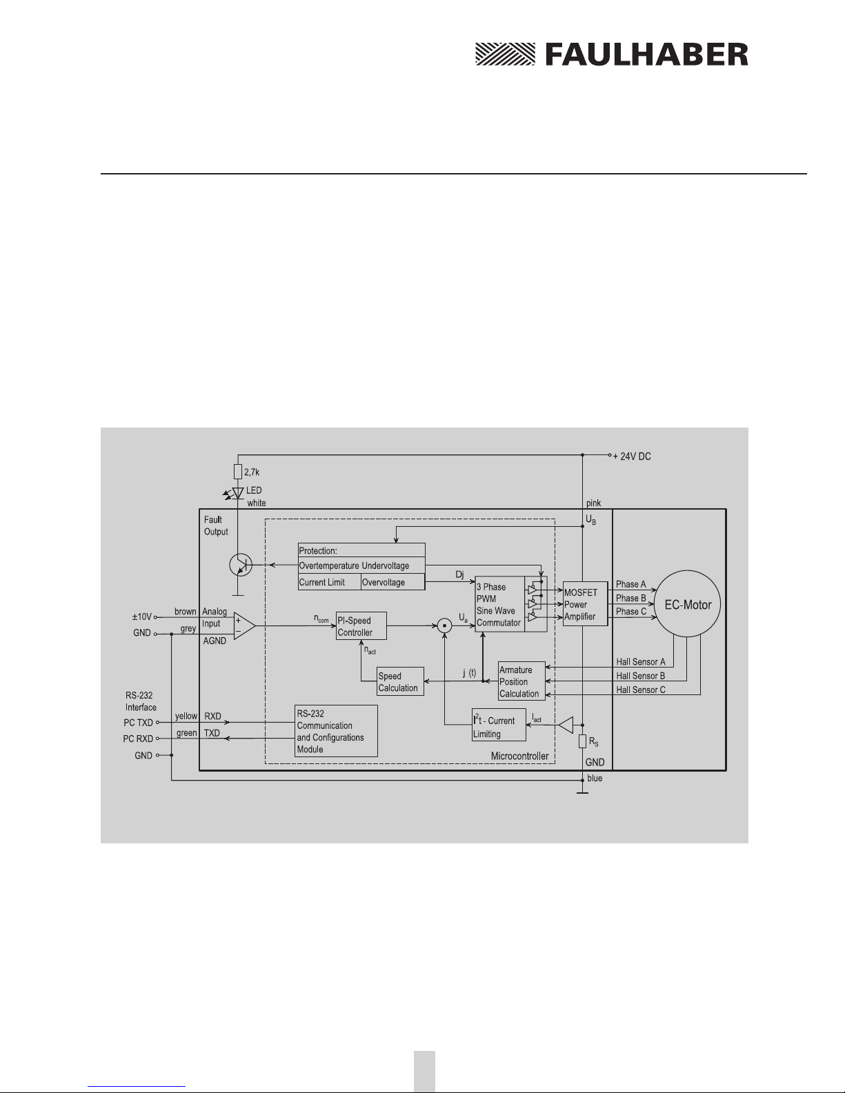
On delivery the 3564K024B C
is configured as a velocity
control. The command speed
is given as a voltage at the
analog input.
In this operating mode the
RS-232 is not required but can
be used to alter configurations.
More on the topic of “Altering
Configurations” to come.
Diagram 2:
Velocity control with voltage signal at the analog input
Analog Velocity Control
10
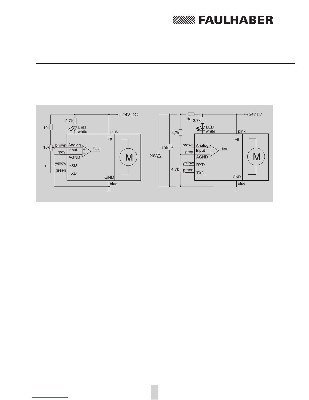
Simple Possibilities to Set Command Velocity with a Potentiometer
Diagram 3 shows the simplest possibility,
but note the following:
■The command velocity depends on
the supply voltage.
■The command velocity is not very accurate
due to the changes in voltage at the
TXD connector.
■The RS-232 port cannot be used.
Diagram 4 shows a more precise circuit,
but note the following:
■The analog GND is separate from the
supply GND.
■The RS-232 is available.
Some Comments about the Input Circuit
The input circuit at the analog input is layed
out as a differential amplifier. If the analog
input is “open” there is already a voltage of 2 V.
That means in this case that the motor would be
turning at a speed of about 2000 rpm. In order
to set 0 rpm the input must be connected over a
low ohm resistor to the analog ground (AGND)
or connected to the AGND-voltage level.
Diagram 3 Diagram 4

11
RS-232 Port and the ASCII Commands
The RS-232 port allows the 3564K024B C to be
connected to a personal computer as well as
various digital controllers, like for example a
SPS or an IPC.
Using the RS-232 Port
■To configure the motor
■Online data analysis
■
Online communications with the motor
during operation
Default Configuration
of the RS-232 Port
■9600 Baud ■8 data bits
■1 stop bit ■No Parity
When working with a terminal program on a PC
one should activate “local echo” and “carriage
return”.
The ASCII Commands
Communication with the PC usually takes place
through a simple ASCII terminal program like
the one provided with the Windows operating
system. Operation becomes more elegant with
the available “Moman” operating program
which provides real time graphics generation for
values like actual speed and position.
Building blocks of the ASCII Commands
1.) Node Address (option...just necessary
in a network)
2.) Command word: a character string,
letters only
3.) Number: in many cases the command word
is followed by a number
4.) The conclusion is always a “carriage return”.
In a terminal program, for example, the enter
or return key.
Example:
V 500 [CR] ... Switch to velocity control
mode and rotate with 500 rpm
GST [CR] ... Get Status ...
LA200 [CR] ... Set absolute position at 200
Spaces (blank characters) are ignored and
capital and lower case letters are allowed.
The answer to the return information command
is always an ASCII Character string.
At the end a “carriage rerturn” [CR] symbol
(Return, decimal code 13) and a LF symbol
(Line Feed, decimal code 10).
Example:
Request the actual postion (POS-Command)
Enter: POS [CR]
Answer: 50000 [CR] [LF]
➔
This means that the motor is now at position
50000, which means 50 turns from zero.

RS-232 Port and the ASCII Commands
12
Saving Configurations
Parameters and configurations
can be saved in an on board
EEPROM chip. That means that
saved programs and configura-
tions are not lost in case of a
loss of power. Upon connec-
tion to the supply voltage the
motor runs under the setup
saved in the EEPROM.
To save parameters in the
EEPROM use the ASCII
Command EEPSAV.
Important:
Setup can be lost in the case of a loss of power during
programming.
Comments about the command table:
Commands that are marked in the instruction manual with a *)
will be saved with the EEPSAV command.
Diagram 5: The operation of the EEPROM
Changing the Baud Rate
The baud rate can be set to the
following values: 1200, 2400,
4800, 9600, 19200 Baud.
Command Function Description Example
BAUD *) Select BAUD Rate Sets the baud rate BAUD9600
for the RS-232 port
Default Setting: BAUD9600
In order to continue working after the baud rate has been
changed in the motor, the baud rate must also be changed
in the PC.

13
RS-232 Port and the ASCII Commands
Setting the Node Address
With the assistance of the
RS-232 Multiplexer Board it
becomes possible to drive
multiple motors from one host.
Use the ASCII addressing
command to address the
individual motors.
Command Function Description Example
NODEADR *) Define Node Defines the node address NODEADR5
Address from (0 bis 255)
GNODEADR Get Node Calls up node address GNODEADR
Address at the host ➔5
Default Setting: NODEADR0
Command Function Description Example
ANSW *) Asynchron Answer ANSW0 ...automatic ANSW1
On / Off answering deactivated
ANSW1 ... automatic
answering active
Important Note:
Only one motor may be connected at the time of addressing.
Otherwise, multiple motors will receive the same node address.
Careful when hosting multiple motors:
If commands are sent without a node address, all the motors in
the network will receive the command. If one calls up the status
of a motor without entering the node address an error will occur
because all the motors will attempt to answer at the same time.
Turning off the Asynchronus Answer Commands
In the case of the Asynchronus Answer Commands problems can
occur even if the node address is given because the answer is not
sent directly after the command is given.
Example: NP20000 ... Notify Position (details to come)
The answer “p” will come only after the motor has reached
position 20000. Other nodes (motors) could be answering at the
same time. If this occurs the data (answers) can be lost.

Configuring the Velocity Control
14
Upon delivery the motor is set
up as a velocity controller. The
input signal is a voltage at the
analog input, for example,
from a potentiometer. By
changing the configuration of
the motor many other sources
for controlling the velocity can
be chosen.
Sources for Velocity
Command Function Description Example
SOR *) Source For Sources for the Velocity SOR 1
Velocity SOR 0: Command velocity at the
RS-232 port
SOR 1: Command velocity with a
voltage at the analog input
SOR 2: Command velocity with a
PWM signal at the analog input
Command Function Description Example
SP *) Load Maximum Loads new maximum SP4000
Speed velocity Arguement in rpm
(from 0 to 30000)
Settings apply to all modes
GSP Get Maximum Calls up maximum speed GSP
Speed ➔ 2500
Command Function Description Example
MV *) Minimum Velocity Sets the minimum speed MV100
GMV Get Minimum Calls up the minimum speed GMV
Velocity over the RS-232 port ➔ 0
a.) Command Velocity with Voltage at Analog Input
In Analog Velocity Mode other setup values can be changed.
Setting the Maximum Velocity
Example: SP5000 ➔The maximum velocity is set
to 5000 rpm. That means that 10 V
at the Analog Input represents a
command velocity of 5000 rpm.
Default Setting: SP10000
Setting the Minimum Velocity:
The lowest possible velocity, at minimum analog voltage,
can be set.
Default Setting: MV0

15
Configuring the Velocity Control
Command Function Description Example
MAV *) Minimum Analog Sets the minimum MAV500
Voltage analog voltage
GMAV Get Minimum Calls up the minimum analog GMAV
Analog Voltage voltage over the RS-232 port. ➔25
Setting the Minimal Analog Voltage
Example: MAV100 [return] ➔100 mV is the necessary minimum
starting voltage. The motor will
not turn if the voltage ranges from
–99 mV to 99 mV.
Default Setting: MAV25
Advantages: While 0 mV at the analog input is normally very
difficult to achieve, 0 rpm can not be accurately set. Setting the
minimal analog voltage > 0 prevents this from being a problem.
The resulting dead zone is also useful becasue the motor will not
start up when small disturbance voltages occur.
Diagram 6: Characteristic curve with a given analog velocity

Configuring the Velocity Control
16
Setting the Direction of Rotation:
Command Function Description Example
ADL *) Analog Direction Armature rotates left ADL
Left with positive voltage at
the analog input
ADR *) Analog Direction Armature rotates right with ADR
Right positive voltage at the
analog input
Command Function Description Example
V *) Select Velocity Activates velocity control V2000
Mode mode and rotates with
the given value
GV Get Velocity Calls up the GV
command velocity ➔500
Default Setting: ADR ... Right rotation with positive voltage.
b.) Command Velocity with Pulse Width Modulation (PWM)
at the Analog Input
The factory setting are:
■Pulse Duty Ratio > 50 % ➔Rotation Right
■Pulse Duty Ratio = 50 % ➔Rotation Stop
■Pulse Duty Ratio < 50 % ➔Rotation Left
The commands SP, MV, MAV, ADL and ADR can also be used
in this mode.
c.) Command Velocity at the RS-232 Port:
Directly following the SOR0-Command the motor continues
rotating with the current command velocity.
Special Setting: Constant Velocity
SOR0 [enter] ➔Switches to RS-232 Mode
V500 [enter] ➔Enter desired velocity
EEPSAV [enter] ➔Saves setting to EEPROM
Now the motor will always start with the saved velocity.

17
Configuring the Velocity Control
Setting an Acceleration:
Command Function Description Example
AC *) Load Command Loads a new value for AC100
Acceleration acceleration Arguement
in Rev/s2
GAC Get Acceleration Calls up current GAC
accelaration value ➔1000
Default Setting: 30000 Rev/s2
This acceleration value makes soft acceleration and braking
in Velocity Control Mode possible.
Direction of Rotation Input:
The Fault Output can be configured to serve as a direction of
rotation switch.
Command Function Description Example
DIRIN *) Direction Input Sets the fault output to DIRIN
function as a direction of
rotation input. (also activates the
limit switch function)
Level and Direction:
Low: 0 V to 0,5 V ... Rotation Left
High: 4 V to Supply Voltage ... Rotation Right
The logic level at the direction of rotation input is dominant to
changes made with the ADR and ADL commands.
When the Fault Output is used as a Direction of Rotation Switch,
it functions with all sources after the setup is initially given over
the RS-232 port.
To take the position limits into account
The position limits (LL-command) will become applicable with
the input of the command APL1. With the input of the APL0
command position limits will be ignored.

Configuring the Velocity Control
18
Command Function Description Example
POR *) Load Proportional Loads controller amplification POR20
Term (values: 0-255)
I *) Load Integral Loads controller integral term I10
Term (values: 0-255)
GPOR Get Proportional Calls up controller GPOR
Term amplification. ➔8
GI Get Integral Calls up the setting for the GI
Term integral term ➔20
Instructions:
1.) Set output configuration
■Sets Source for Command Velocity: RS-232
➔SOR0 [enter]
■Proportional Term = 8 (example)
➔POR 8 [enter]
■Integral Term = 20 (example)
➔I20 [enter]
■Sets Velocity to 1/3 of Maximum Application Speed
(only an example value)
➔V1000 [enter]
■Sets Acceleration to Maximum Application Value
(only an example value)
➔AC10000 [enter]
2.) Proportional Term = 13 (Step Width 5, smaller later)
3.) Velocity jumps from 1/3 to 2/3 the Maximum Application Speed
(only an example value)
4.) Velocity jumps from 2/3 to 1/3 the Maximum Application Speed
(only an example value)
5.) Repeat steps 2-4 until the controller becomes unstable. Then
reduce the Proportional Term until the stabilty is achieved.
6.) Repeat steps 2-5 with the Integral Term.
Fine Tuning the Digital Filter
The digital filter parameters can be adjusted to improve the
dynamic performance. These parameters should be carefully
chosen to fit the application because they have a great influence
on performance.
19
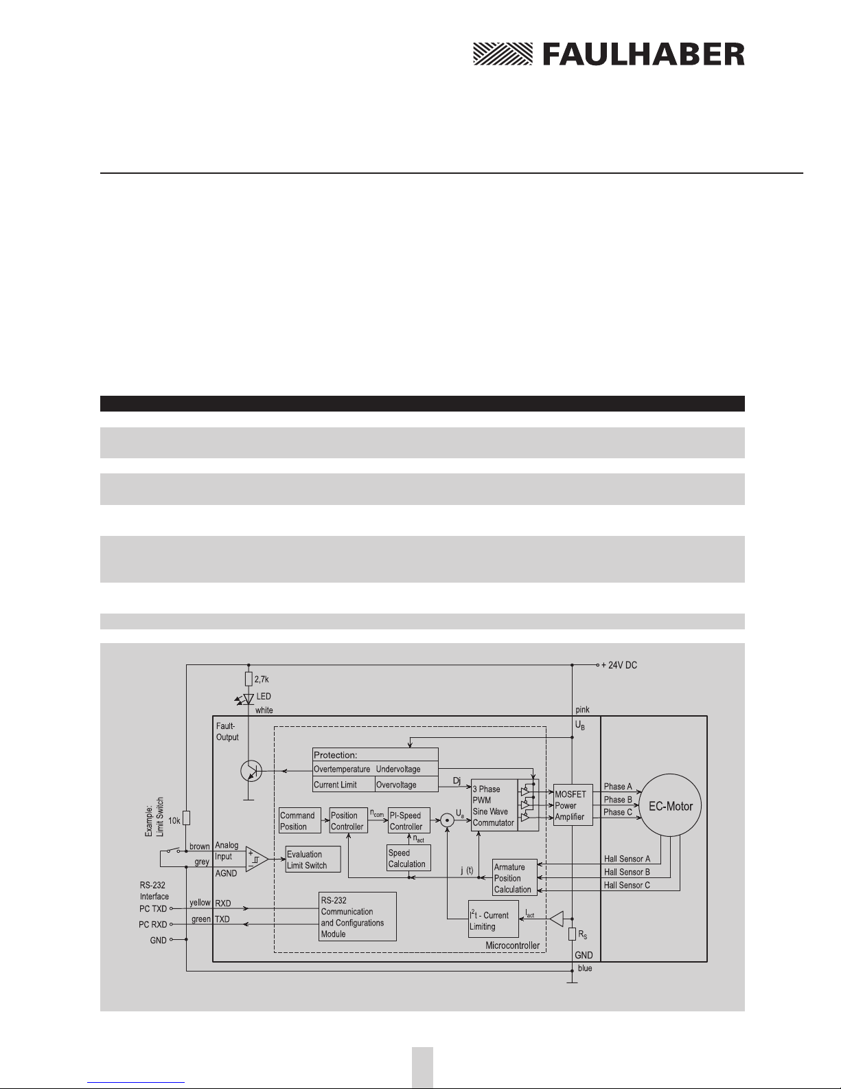
Position Control
Diagram 7: Position control with a reference switch at the analog input
The following Command Sequence is necessary to switch from Speed Control Mode (factory setting)
to Positioning Mode:
SOR0 [enter] ➔Switches to RS-232 Communication in Speed Control Mode
LR0 [enter] ➔Load Relative Position 0
M [enter] ➔Switches to Positioning Mode
Positioning commands:
Command Function Description Example
M *) Initiate Motion Activates positioning mode and starts positioning M
LA Load Absolute Position Loads the new value for the absolute position. LA100000
Arguement: 1000 indicates 1 revolution.
LR Load Relative Position Loads a new relative position LR5000
SP *) Load Maximum Speed Loads a new maximum velocity. SP4000
Arguement: rpm from 0 to 30000
AC *) Load Command Loads a new value for acceleration. AC100
Acceleration Arguement: U/s2from 0 to 30000
NP Notify Position A “p” will appear on the screen when the motor has NP10000
rotated beyond a given position. asynch ➔p
NV Notify Velocity A “v” will appear when a given velocity has been NV5000
achieved. asynch ➔v

Position Control
20
Standard Positioning Sequences
1.) Enter the acceleration and the maximum
velocity (rpm)
AC50 [enter] ➔Sets acceleration to 50 Rev/s2
SP3000 [enter] ➔Sets maximum velocity
to 3000 rpm
These values are set until they are changed or
the motor is turned off.
2.) Set Command Position
Either: a.) LA40000 [enter] ➔Sets
command position to Absolute
Position 40000
Or: b.) LR10000 [enter] ➔Adds 10000 to
the current Command Position
3.) Start Positioning Sequence
M [enter] ➔Depending upon the choice
of a.) or b.) from step 2.) the positioning
sequence will start from either 40000 or
current command position +10000. The
motor will turn to this position with the
given acceleration and maximum velocity.
By repeating steps 2.) and 3.) one can set the
motor to rotate to other positions one after
the other.
Combined Motion Profiles
Through well chosen values (Maximum Velocity,
Acceleration, end Position) entered during a
positioning sequence one can create complex
motion profiles. After any values have been
changed during a positioning sequence a new
motion-start (the M command) must be initia-
ted. The commands NP (notify position) and NV
(notify velocity) can be used to aid in controlling
the sequence.
Diagram 8: Combined motion profile in comparison to a trapezoidal profile
Sequence (corresponding command sequences
after the notify requirements have been met)
Start a.) b.) c.) d.)
LA[POS3] AC[AC2] AC[AC1] SP[SP2] AC[AC4]
AC[AC1] NV[V2] NP[POS1] AC[AC3] NP[POS3]
SP[SP1] M M NP[POS2] M
NV[V1] M
M
Setting the Digital Filter
The digital filter settings in Positioning Mode
can also be optimized just as in Speed Control
Mode (see above).
Table of contents
Other Faulhaber Engine manuals


Popular Engine manuals by other brands

Siemens
Siemens 1FT7 Series instructions

Orion
Orion EQ-1M user manual

Sumitomo
Sumitomo Beier Variator Series Maintenance manual

Chevrolet
Chevrolet 5.7L Corvette 2004 Shop Manual

ORION TELESCOPES & BINOCULARS
ORION TELESCOPES & BINOCULARS AstroTrack 21047 Addendum to instruction manual

Mitsubishi
Mitsubishi 4D56 user manual


