BN Products BNG4000iE User manual
SILENT INVERTER GENERATOR
USER’S MANUAL
owner's manual

2
Thank you for choosing our inverter generator.
This manual covers the right operation and maintenance. Before operating,
please read it carefully,then you’ll gain good rewards.
All technical data and drawings in this manual are consistent with the latest
products while publication. As a result of revisions and other changes, the
contents of this manual may be slightly different from the actual situation. Our
company reverses the right to make changes at any time, without notice and
without incurring any obligation, please understand.
The copyright of this instruction manual belongs to our company. No
reproduction is allowed without the written consent of Our company. All rights
reserved.
This manual is a permanent part of the generator set and will be resold
together with the generator set if it is resold.

3
Safety Warning
The personal and property safety of you and others is very important.Please
read carefully the extremely important safety warnings we have written in the
manual and the label of the generator set.
Safety warnings can alert you to potential dangers that may harm you and
others.
There are one of these three symbols :”Danger”,”Warning”,”Notice”in front
of safety warning. Details as below:
If you do not follow the instructions, your life will be in danger or you will be
seriously injured.
If you do not follow the instructions, your life will be in danger or you will be
seriously injured.
If you do not follow the instructions, you will be slightly injured.
If you do not follow the instructions, your generator set and other property
may will be damaged.

4
Content
Safety Warning ..................................................................................................... 3
Content................................................................................................................... 4
1. Safety Instruction............................................................................................ 6
1.1 Safety Specification............................................................................. 6
1.2 Special Request.................................................................................... 7
2. Safety Warning Label ..................................................................................... 8
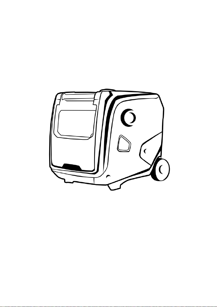
3. Components Identification............................................................................. 9
3.1 Components Feature ........................................................................... 9
3.2 Control Panel.......................................................................................10
3.3 Type and Serial Number...................................................................11
4. Control System...............................................................................................12
4.1 Engine oil alerting system(YELLOW).............................................12
4.2 Overload Indicating Light(RED).......................................................12
4.3 AC Indicating Light(GREEN)............................................................13
4.4 ECO Switch..........................................................................................13
4.5 Ground Terminal.................................................................................14
5. Preparation......................................................................................................15
5.1 Fuel Oil..................................................................................................15
5.2 Engine Oil .............................................................................................16
5.3 Recoil Starter.......................................................................................17
5.4 Fuel Tap................................................................................................17
5.5 Choke Valve.........................................................................................18
5.6 AC Breaker Protector.........................................................................19
5.7 Ground Terminal.................................................................................19
6. Generator Use................................................................................................20

5
6.1 Connect to Household Power Supply.............................................20
6.2 Generator Grounding.........................................................................21
6.3 AC Power..............................................................................................21
7. Starting the Engine........................................................................................24
7.1 Recoil Start...........................................................................................24
7.2 Electric Start.........................................................................................24
8. Stopping the Engine......................................................................................27
9. Maintenance...................................................................................................28
9.1 Engine Oil Replacement....................................................................30
9.2 Air Filter Maintenance........................................................................31
9.3 Spark plug.............................................................................................32
10. Storing............................................................................................................33
11. Troubleshooting...........................................................................................34
12. Electrical Diagrams.....................................................................................35
13. Technical Specifications............................................................................36
6
1. Safety Instruction
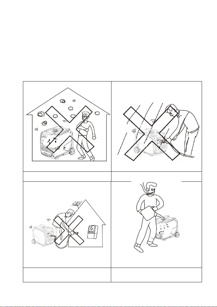
1.1 Safety Specification
Please read and be well known about the manual before operating.
Familiarity with the safe operating procedures of generators can help you
avoid accidents.
Don’t use it indoor.
Don’t use it in damp environment.
Do not connect directly to household
appliances.
Don’t smoke while adding fuel oil.
7
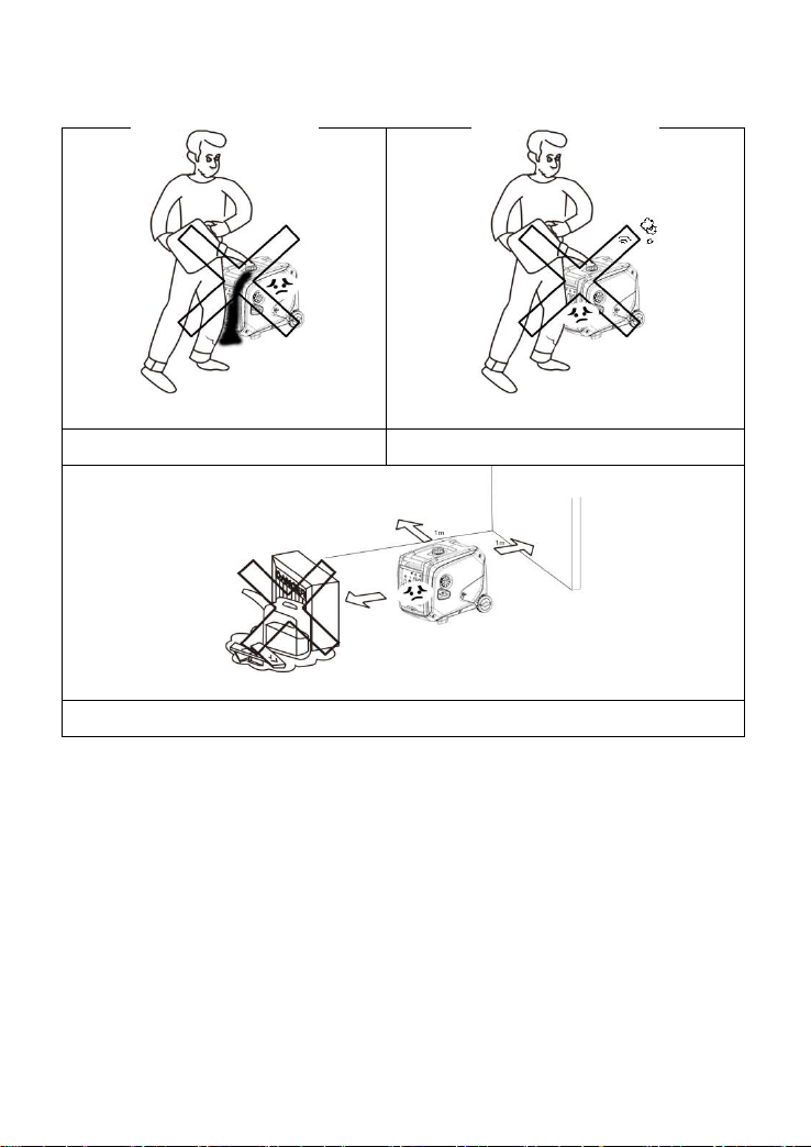
Do not spill oil when fueling.
Please stop running before fueling.
Please remove the combustible materials away at least 1m.
1.2 Special Request
Electrical equipment includes unexposed wires and plugs.
The protecting breaker should be matched with generator. The
application parameters and performance should be totally
matched if changing.
Well grounded before using
If need extension wire, it must meet the requests as below: 4mm2,
length no more than 100m.
8
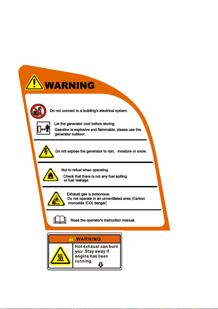
2. Safety Warning Label
Please read the manual carefully before using.
Safety warning label

9
Muffler cover
3. Components Identification
3.1 Components Feature
Left cover
Muffler exhaust pipe
Maintenance
Cover Knob
Maintenance
Cover
Five in One
Switch
bar
Control
panel
Handle
Starter handle
Fuel Tank Cap

10
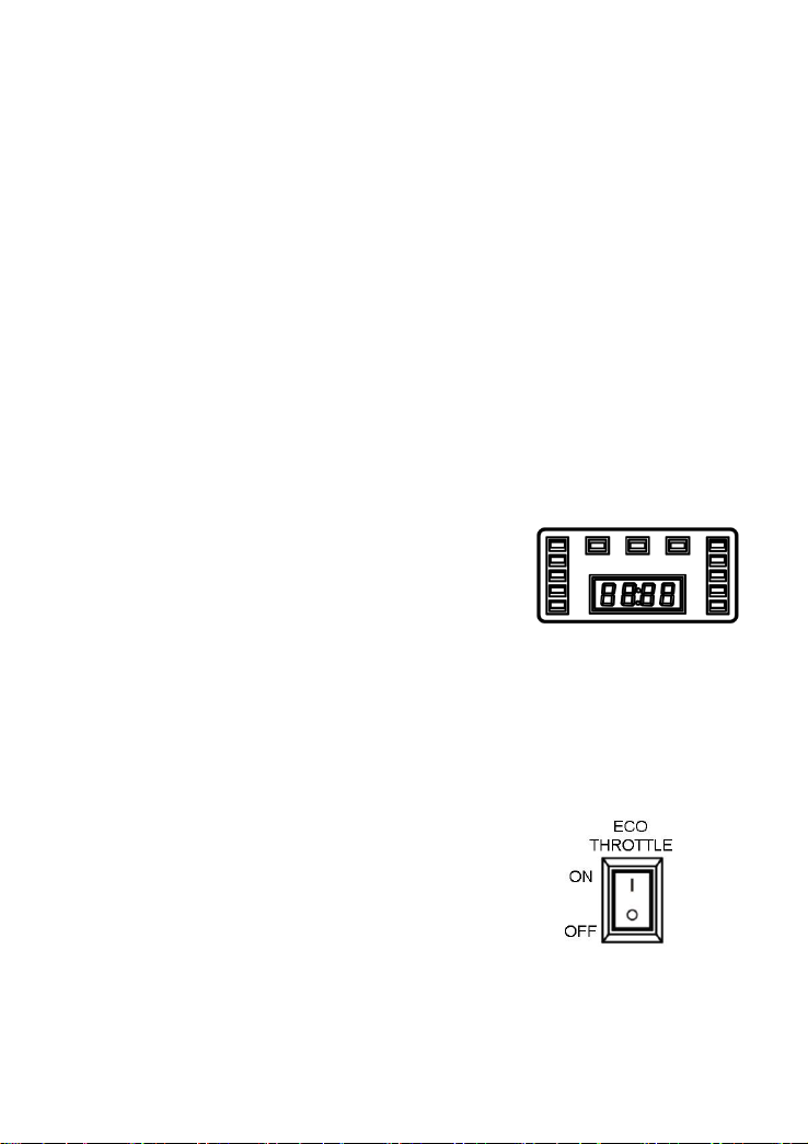
3.2 Control Panel
(Factory will adjust the panel according to different configuration.
Please note that subject to change without prior notice. )
1 Digital meter
2 ECO(Economy system control)
3 Reset button
4 AC protector
5 DC protector
6 DC socket
7 USB
8 Parallel socket
9 AC socket
10 Ground terminal
5 6 7 8 9 10
1 2 3 4
H4500iS/ H4500iE

11
3.3 Type and Serial Number
Type Product No.
Serial No.
.

12
4. Control System
4.1 Engine oil alerting system(YELLOW)
The engine oil protection system will stop the
engine automatically, and the engine oil
indicating lights, while the oil in crankcase is
under safe line;Fill the engine oil to the oil level,
it can be restart again.
If the engine oil alerting light flashes for few seconds, it means the oil
capacity is insufficient. Refill the oil and restart the engine.
4.2 Overload Indicating Light(RED)
When the overload indicating light is on, the generator detects that the
output of the phase-side electrical equipment has been overloaded,
causing the converter to overheat or the AC voltage to rise. Then the
AC protector works and stops the generator to protect the generator
and the equipment which connects with it. The AC indicating
light(GREEN) is off, but overload indicating light (RED)is on,engine will
not stop working.
While the overload light is on, and the generator has no output, please
take following measures:
13
1. Turn off the connected electrical equipment and stop engine.
2. Reduce the total power rate of connected electrical equipment
within the rated output range.
3. Check whether the cool air inlet is blocked by foreign matters and
whether the relevant control parts are abnormal. If there is any problem,
remove it immediately.
4. Restart the engine after checking.
Notice: When using the electrical equipment with high starting
current(like compressor and sinking pump...), the overload
indicating light may will flash for few seconds. But this doesn’t
belongs to troubles as aforementioned.
4.3 AC Indicating Light(GREEN)
The AC indicating light will be on while the
engine starts and keep normal output.
4.4 ECO Switch
① “ON”
While the ECO switch is on position of “ON”, the equipment will control
rotating speed according to the connected load, so as to get good fuel
oil consumption and low noise.
② “OFF”
While the ECO switch is on position of “OFF”, whether it connects with
load, the engine also runs at a rated rotating speed.(3600r/min)

14
NOTICE: Cause it needs heavy start current, ECO switch must be
off while using compressor.
4.5 Ground Terminal
The ground terminal is connected to the ground wire to prevent electric
shock. The generator should be connected to ground while the
electrical equipment connecting to ground.
Ground terminal
15
5. Preparation
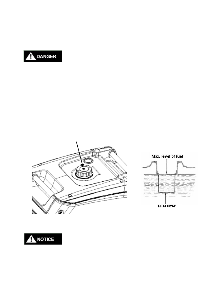
5.1 Fuel Oil
Fuel oil is flammable and toxic. Please read the safety
instruction carefully before refueling.(See Page 7 for
details.)
Do not fill the tank with too much oil, or the oil will
overflow when the tank gets warm.
After refueling, make sure the fuel tank cover is
tightened.
To avoid damage the plastic outer case, please wipe off residual
gasoline with a clean, soft cloth after refueling.
Fuel tank cap
16
You must use unleaded gasoline. The leaded one would damage
the internal parts of the engine.
Suggestion: unleaded gasoline
Fuel oil tank capacity: 12.5L
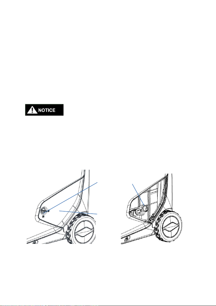
5.2 Engine Oil
The generator is not injected with engine oil when leaving the
factory. Please do not start it before injecting enough engine oil.
1.Please place the generator on the horizontal plane.
2.Turn the knob① to “ON”,and put down oil maintenance door②.
3.Open the fuel cap③.
4.Refuel a recommended amount of oil and tighten the cap.
5.Replace oil maintenance door and turn knob to “OFF” position.
①
②
③
17
5.3 Recoil Starter
Pull the starter handle up gently until resistance is felt, then pull it out
suddenly.
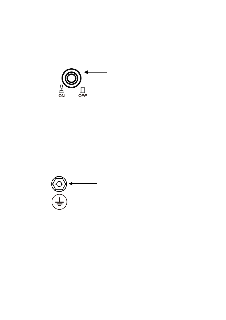
5.4 Fuel Tap
Fuel tap is a device that controls the flow of fuel from the tank to the
Recoil Starter
18
carburetor. Please make sure it is on position of “OFF” after stop
working.
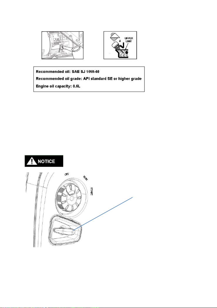
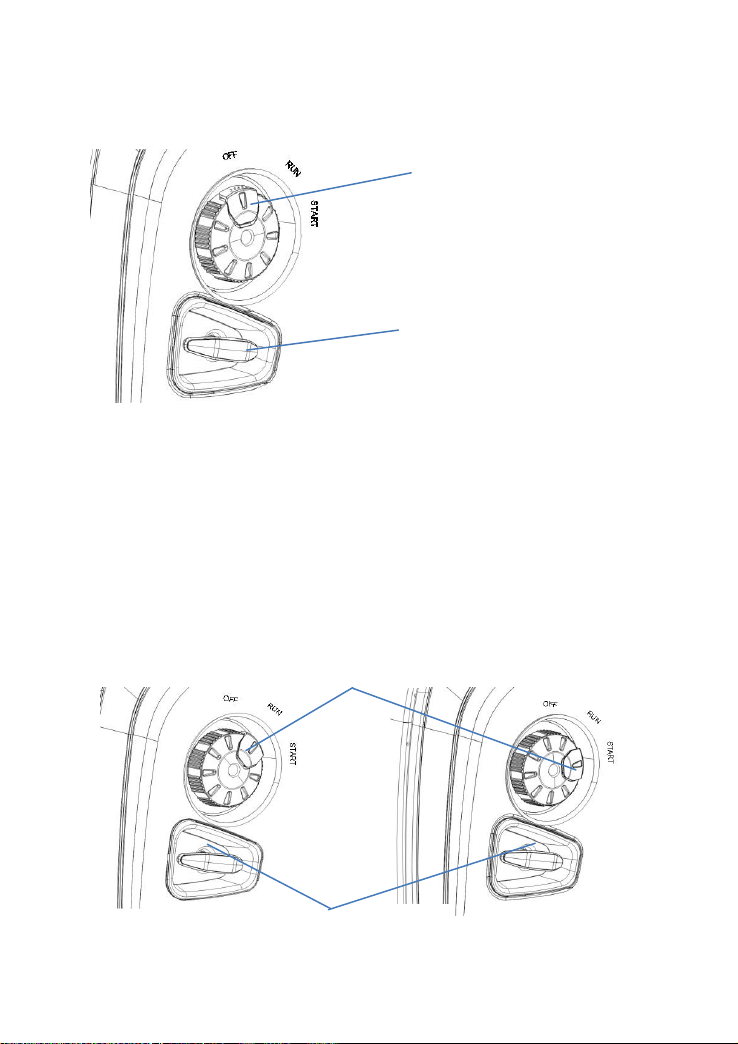
5.5 Choke Valve
Choke valve is used to provide a rich mixture of oil to a gasoline engine
when the cold engine is started. When the cold gasoline engine starts,
rotate the start switch to put the start button in the "START" position.
When the gasoline engine starts up warmly, the starting switch is
rotated to put the starting button in the "RUN" position.
Start Button
Recoil Starter
Start Button
Recoil Starter
19
5.6 AC Breaker Protector
Overload current can turn off the breaker protector automatically. The
load shortened and overload should be avoided. If the breaker protector
closed automatically, please must test the loading before opening.
5.7 Ground Terminal
Ground terminal connects the earth line for prevention of electric shock.
When the electric device is grounded, be sure to ground the generator
also.
AC breaker protector
Ground Terminal

20
6. Generator Use
· Applicable temperature:-5℃~40℃
· Applicable humidity: below 95%
· Applicable altitude:areas below 1000 meters(If you operate your
engine at altitudes above 1000 meters, reduce the engine power or
modify the carburetor by contacting the suppliers.
6.1 Connect to Household Power Supply
When the generator is connected to the household power supply as a
standby power supply, it should be connected by a special electrician or
someone familiar with the electricity.
After connecting the load to the generator, carefully check whether the
electrical connection is safe and reliable. If there is incorrect electrical
connection, it may cause generator damage, combustion or fire.
Table of contents
Other BN Products Portable Generator manuals


Popular Portable Generator manuals by other brands


Krüger Technology
Krüger Technology KGVC3000 instruction manual

Guardian
Guardian 04389-1 Installation and owner's manual

Briggs & Stratton
Briggs & Stratton Elite 030206 owner's manual

IVT
IVT GN-750B manual

Hensel-Visit
Hensel-Visit Nova D 1200 user manual

Briggs & Stratton
Briggs & Stratton 1894 owner's manual