BNT PRO-100Q User manual

7.1 Alignment by view finder & shading plate
7.2 Alignment using LEVEL LED
7.3 Alignment by audio tone indicator
7.4 Alarm memory function
7.5 Environment function
8.1 Four channel frequency selection
8.2 Beam power selection
8.3 Response time changeover function

The PRO-100Q/200Q are quad photoelectric detectors designed to activate an alarm relay upon the detection of
Intruder through 4 pulsed infrared beams.
For stable operation, the PRO-100Q/200Q are equipped with the following features.
■ High power infrared
The active infrared transmission is exceptionally strong with a maximum arrival distance ten times greater than
the specified protection distance.
■ Four frequency selections
4 separate choices of frequency avoids cross-talk in stacked or long linear installations.
■ Beam transmission strength selection
2 levels of beam transmission strength which can be set to suit the protection distance.
■ Auto-gain lock
Optimal sensitivity gain is automatically set at any coverage distance up to the maximum protection distance.
(Audible tone indicates setting is completed)
■ Environmental module
Environmental trouble signal is sent when beam reception level is reduced below an acceptable level.
■ Programmed AGC function
Sensitivity is automatically increased in bad weather to contend with fog, rain, of frost.
■ Alarm memory indicator
Alarm memory LED located on Receiver can be manually reset (at sensor) or remotely controlled via panel.
■ Audible signal for alignment
An alignment tone aids in quick set-up of beams for electrical measurement of alignment
■ Retransmitting function
The advantage is elimination of wiring from a detector or switch, back to the control panel.
■ Other features
Monitor output, Level LED , Response time changeover, Tamper output.
WARNING ! Indicate that incorrect operation causes significant danger of accident resulting in death or serious
Injury to the user.
CAUTION ! Indicate that incorrect operation causes possibility of injury to the user of damage to the unit.
Read the following prior to installing, wiring and regular maintenance.
CAUTION ! DO NOT INSTALL THE UNIT
① where trees, plants, of falling leaves will block the beams.
② where intense source of light, sunlight will be reflected directly into the receiver optics.
A foreign light incoming within ±3° angle of each receiver axis may cause false alarms.
③ on movable surfaces.
④ where subject to foul water or sea spray.
⑤ where over the max range on each model.
⑥ where subject to strong electrical noise or RFI
⑦ where subject to strong vibration.
⑧ where subject to corrosive or explosive gas.
AVOID
① external temperature and humidity.
② magnets or any magnetized material.
③ running power and output wires near voltage power sources.
IMPORTANT
① Face upper/lower optical modules on the transmitter and receiver towards each other.
② Be sure of the beam in alignment optical modules can be adjusted within ±90° horizontally and ±3° vertically.
WARNING !
① Do not perform installation and wiring when it thunders.
② Do not supply power until all wiring is completed.
③ Keep power between 10 V ~ 28 VDC anytime.
④ Do not disassemble or modify the unit.
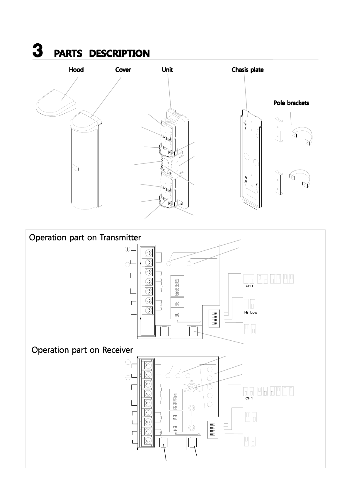
Mirror (upper)
Vertical
adjustment
screw (upper)
Terminal
Vertical
adjustment
screw (lower)
Operation part
(see below)
Horizontal
adjustment
screw (upper)
Horizontal
adjustment
screw (lower)
Mirror(lower)
View finder
View finder
Shading plate
Operation LED
Re-transmit LED
CH 2 CH 3 CH 4
Beam channel (1,2)
Beam power (3)
O
n
O
f
f
Retransmitting (4)
Tamper switch
CH 2 CH 3 CH 4
Beam channel (1,2)
Sound tone (3)
O
n
O
f
f
Alarm memory (4)
Level LED on/off
Tamper switch
Level meter
Status LED (Memory /Alarm / ENV)
Response time adjustment
Power 10V ~ 30V DC
(non-polarity)
Re-transmitting (input)
Tamper
Power 10V ~ 30V DC
(non-polarity)
Alarm output
Environment output
Tamper
O
n
O
f
f
POWER
TAMPER
RETRANS
OPERATION
Re-TRANSMIT
N.C
N.O
Channel
1 2
CH1
CH2
CH3
CH4
1 2 1 2 1 2
Beam power
Low
High
3
Off
On
44
Re-transmit
ON
1 2 3 4
ENV
TAMPER
POWER
ALARM
ENV
ON
1 2 3 4
ALARM
MEMORY
+
_
N.C
N.O
N.C Monitor
Excellent
Good
Fair
Realign
Poor
+
_
Channel
1 2
CH1
CH2
CH3
CH4
1 2 1 2 1 2
Sound
Off
Memory
On
33
Off
On
44

A
B
C
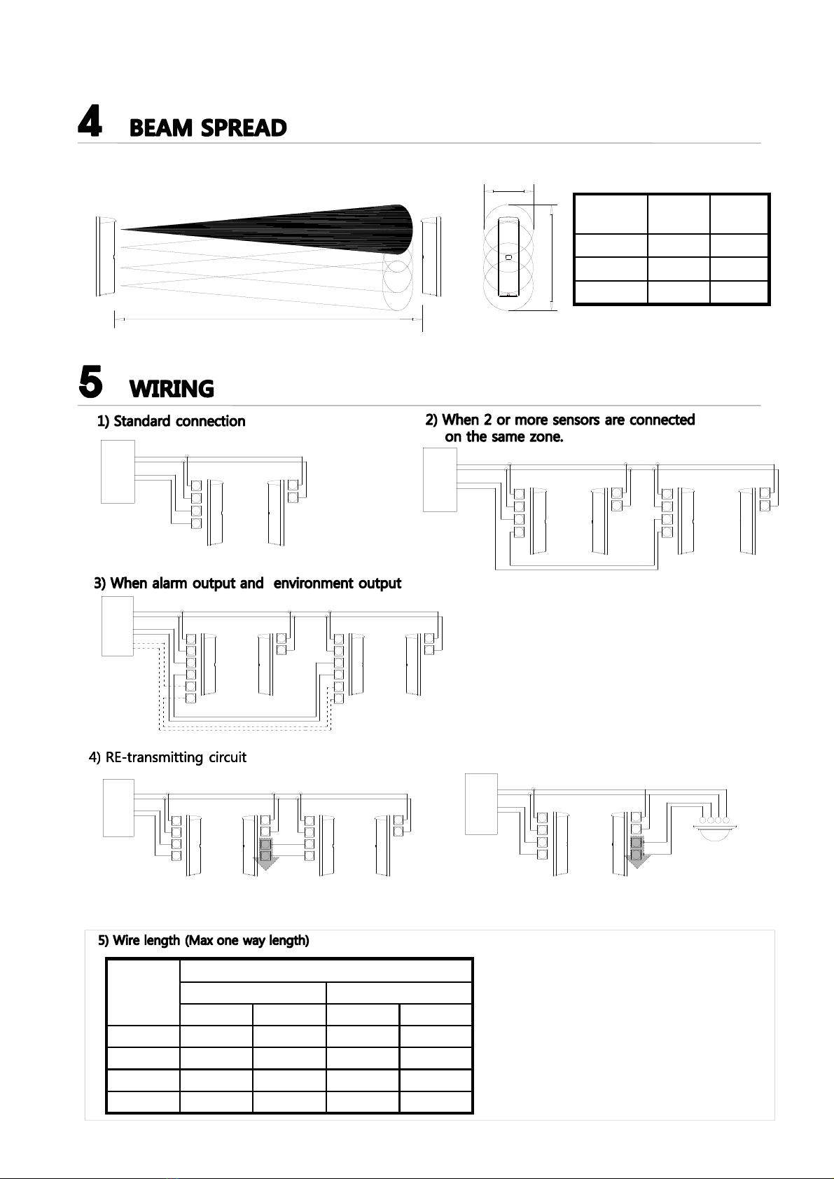
The beam spread sngle is 1.4°. Refer to the right table and the diagrams below
to determine the installation conditions.
Distance
(A)
Spread
(B)
Spread
(C)
100m 2.5m 2.7m
150m 3.7m 4.0m
200m 5.0m 5.2m
RX TX
+
-
COM
N.C
+
-
POWER
DC 12V
Alarm
input
Control Panel
RX RX
TX TX
+
-
COM
N.C
+
-
+
-
COM
N.C
+
-
POWER
DC 12V
Alarm
input
Control Panel
RX RX
TX TX
+
-
COM
N.C
+
-
POWER
DC 12V
Alarm
input 1
Alarm
input 2
Control Panel
+
-
COM
N.C
+
-
COM
N.C
COM
N.C
RX RX
TX TX
COM
N.C
+
-
COM
N.C
+
-
POWER
DC 12V
Alarm
input 1
Control Panel
+
-
COM
N.C
+
-
Wire
Gauge
Maximum distance (meter)
PRO-100Q PRO-200Q
12V DC 24V DC 12V DC 24V DC
AWG 22 100 900 90 800
AWG 20 190 1,700 160 1,500
AWG 18 280 2,600 250 2,200
AWG 14 600 5,370 500 4,570
Note1) Max. wiring distance when two or more sets
are connected is the above value divided
by the number of sets.
Note2) Be sure the control panel is equipped with
adequate standby battery and charging circuit.
Use 12v (at least) Ni-cd or lead acid battery
with minimum capacity of 0.5 AH.
RE-TRANSMITTING
(INPUT)
+
-
POWER
DC 12V
Alarm
input 1
Control Panel
RX TX
COM
N.C
+
-
NC COM
+
-
COM
N.C
RE-TRANSMITTING
(INPUT)
* The advantage of this method is elimination of wiring from a detector or switch, back to the control panel.
Detector or switch

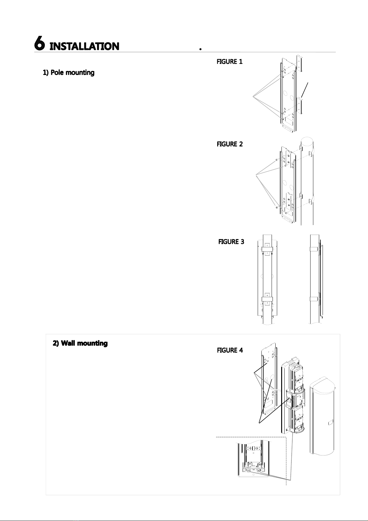
- Chose an appropriate mounting location for the system.
Install the poles with a clear linesight between the transmitter
and the receiver
- Loosen the transmitter’s cover mounting screw and remove
the cover.
- Loosen the 2 unit mounting screws and remove the chassis
by sliding it down againse the unit.
- Attach the mounting plates to the chasis with the clamping
screws (short) (see FIGURE 1)
- Firmly attach the chassis to the poles with the U-clamps and
the screws (long) (see FIGURE 2). Make sure the transmitter
is mounted in direct line-of- sight with the receiver.
- Route wiring through the chassis wire entrance, leaving
enough wire to access the transmitter’s terminal strip.
-Route wiring through the transmitter’s wire entrance.
- Slide the transmitter onto the chassis. Tighten with the unit
mounting screws.
- Repeat this mounting process for the receiver. Make sure it is
mounted in direct line-of-sight with the transmitter.
- Loosen the transmitter’s cover mounting screw and remove
the cover.
- Loosen the 2 unit mounting screws and remove the chassis
by sliding it down against the unit.
- Route wiring through the wire entrance of the chassis.
Leave enough wire to access the transmitter’s terminal strip.
- Mount the chassis to the mounting surface with the chassis
mounting screws.
- Route wiring through the wire entrance of the transmitter.
If surface mounting is used, knock-out the thin-wall wire
entrance at the bottom of the transmitter.
- Reattach the transmitter to the chassis.
- Repeat this mounting procedure for the receiver.
Make sure it is mounted in direct line-of-sight with the
transmitter.
Clamping
Screw
(short)
Clamping
Screw (long)
Pole
Diameter
38~43 mm
Chasis mounting
Screws (included)
Wire entrance
Unit mounting
screws
Completed
of chassis plate

Looking through the view finder,
locate the other detector in the
center of the sights by adjusting
vertically and horizontally.
Vertical adjustment
STEP 1 Rough alignment by view finder
STEP 2 Upper mirror fine adjustment
STEP 3 Lower mirror fine adjustment
STEP 4 Final checking after removing the “Shading plate” from the mirror
Looking through the view finder, locate the other detector in the center
of the sights by adjusting vertically and horizontally.
Horizontal adjustment
Course adjustment
Fine horizontal
adjustment
Connect the volt-meter to
monitor jack input on Receiver’s
(+) and (-) ,then finetune
optical alignment
10V DC
Range
Adjust the optical alignment for Transmitter
and Receiver one at a time
Put the attached “Shading plate” on the
lower mirror of both the Transmitter and the
Receiver
Horizontal
alignment
screw
Vertical
alignment
screw
Adjust the vertical (or horizontal) alignment
Screw to obtain the maximum voltage from
the monitor jack
10V DC
Range
Check the voltage using
the monitor jack and
make any fine
adjustments the
lower mirror.
Secondly, adjust the lower mirrors.
After the final adjustment are made on th upper
mirror carefully without moving mirror remove
“shading plate” from the lower mirrors and
place them on the upper mirrors of both the
Transmitter and receiver
After the vertical and horizontal adjustment
are made, recheck the voltage from monitor
jack is over 3.0 V.
If not, adjust the optical alignment again.
Level Monitor
Jack output
Audio tone
(beep)
Excellent 2.6V ~ 3.0 V continuous
Good 2.0 V ~ 2.5V Fast
(0.5 sec)
Fair 1.3 V ~1.9 V
Realign 0.6 V ~1.2 V Slow
(1.0 sec)
Poor 0.5 V or less
SENSITIVITY CHART
Carefully remove the “shading plate” from the mirror of both
Transmitter and receiver also check the voltage from the monitor jack
again.
Shading plate
Then check again that the voltage from monitor jack
is more than about 3.0 V if not, adjust the optical
alignment again.
Then check again that the voltage from monitor jack
is more than about 3.0 V if not, adjust the optical
alignment again.

■ Beam alignment using LEVEL LED
Excel
Good
Fair
Realign
Poor
The alignment level indicators have 5 LED’s, each LED represents the level of alignment, ranging
from poor to excellent.
Each LED will indicate 3 steps of alignment, slow flicker = okay, fast flicker=better,
continuously on = best
Slow flicker
=Okay
Fast flicker
=Better Continuously on
=Better
■ Audio tone indicator
1) Initial beam alignment can be achieved by using
the alignment tone indicator.
2) Attach the shading plates (stored on sides of both
Transmitter and Receiver. Turn the receiver
3) Alignment tone switch to ON.
4) Adjust the optics with the adjustment screws until
highest tone is reached.
5) Reverse the procedure. i.e. attach shading plates to
upper optics of Transmitter /Receiver and repeat
adjustment
6) After adjustment, replace the shading plates in storage
areas of Transmitter / Receiver.
7) Turn the alignment tone indicator to OFF
(Dip switch 3 ).
ENV
TAMPER
POWER
ALARM
ENV
ON
1 2 3 4
ALARM
MEMORY
+
_
N.C
N.O
N.C Monitor
Excellent
Good
Fair
Realign
Poor
+
_
Channel
1 2
CH1
CH2
CH3
CH4
1 2 1 2 1 2
Sound
Off
Memory
On
33
Off
On
44
■ Alarm memory function
The alarm memory LED indicates which sensor has triggered when two or more sensors are placed on a zone.
An audible tone in addition is an optional selection. (Alignment alarm memory switch to ON)
Alarm output
Memory LED
5 min 5 min
60 min (re-trigger)
55 min (flickering)
The memory LED will light five minutes after an alarm signal and then continue to flicker for 55 minutes
before returning to normal mode. If additional alarm signal are triggered, the process repeats.
Audio tone
Alarm
memory
RECEIVER
■ Environment function (Receiver)
Environment function will send a trouble signal
when the beam strength is below an acceptable level
due to heavy fog, rain, snow or other changes
in the installation site.
The trouble signal output continues as long as the beam
strength is below an acceptable level.
It will reset when the environmental conditions clear
Status LED
+
_
N.C
N.O
N.C AGC
ENV
TAMPER
50 700
350
500
200
POWER
ALARM
ENV
ON
1 2 3 4
Excel
Good
Fair
Realign
Poor
ALARM
MEMORY
Output

8.1) Four channel frequency selection
- The beam pairs may be set at various frequency levels to avoid crosstalk between units which are stacked, in-line. Or other
configurations which have the potential of spill-over transmission from to another .
- Set the frequency level as illustrated.
Make sure Transmitter and receiver of pair are set
at same channel !
paired Transmitter / Receiver will not set up unless
set at the same channel.
CH 2 CH 3 CH 4
TX TX TX
RX RX RX
1 ch 1 ch 1 ch 1 ch 3 ch 3 ch
TX
TX
RX
RX
1 ch 1 ch
3 ch 3 ch
1 ch 1 ch 1 ch 1 ch 2 ch 2 ch
3 ch 3 ch 3 ch 3 ch 4 ch 4 ch
TX TX TX
RX RX RX
TX TX TX
RX RX RX
TX TX
TX
TX
RX
RX
RX
RX
1 ch
1 ch
3 ch
3 ch
1 ch
3 ch
3 ch
1 ch
TX TX
TX TX
RX
RX
RX
RX
1 ch
3 ch
2 ch
4 ch
2 ch
4 ch
1 ch
3 ch
1 ch
3 ch
2 ch
4 ch
2 ch
4 ch
1 ch
3 ch

8.3) Response time changeover function
This feature can be used to alert the response time of the
beam to best fit the application.
Exercise caution in using the 700msec setting.
Non-detection of fast moving human could result.
Run at full speed
(50 msec)
Walk with quick steps
(150msec)
Walking
(250msec)
Walk with slow steps
(500msec)
Go over a
fence
(700msec)
Symptom Possible cause Remedy
Operation LED does
not light
1.Disruption of power or inadequate power
2.Bad wiring connection or broken wire, short
1.Correct power source
2.Check and correct wiring
Receiver Alarm LED
Does not light when
The beam is broken
1.Disruption of power or inadequate power
2.Bad wiring connection or broken wire, short
3.Reflecton of beam is flooding receiver and sent
into the receiver
4.4-Beams are not broken simultaneously
5.Beam interruption time is shorter than response
time
1.Correct power source
2.Check and correct wiring
3.Remove reflecting object.
4.Ensure all beams are broken at same time
5.Adjust response time
Receiver Alarm LED
Stays lit
1.Alignment is off
2.Shading object between transmitter and receiver
3.Optics of units are soiled
4.Frequency channel setting on transmitter does
not match with that on receiver
1.Check and adjust
2.Check site/remove any possible obstacles
3.Clean the optics with a soft cloth
4.Readjst to the same channel
Intermittent alarm 1.Bad wiring connection
2.Change of supply voltage
3.Shading object between transmitter and receiver
4.The wiring of power machine is located nearby
transmitter and receiver
5.Unstable installation of transmitter and receiver
6.Optics of unit are soiled
7.Improper alignment
8.Small animals may pass through the 4 beams
9.Beam power switch is set at L, which does not
keep enough sensitivity allowance
1.Check again
2.Stanilize supply voltage
3.Remove the shading object
4.Change the place for installation
5.Stabilize
6.Clean the optics with soft cloth
7.Check and re-adjust
8.Change environments or the place for installation
9.Set beam power switch at H and make the unit
gain-locked with receiver cover detached
ENV
TAMPER
POWER
ALARM
ENV
ON
1 2 3 4
ALARM
MEMORY
+
_
N.C
N.O
N.C Monitor
Excellent
Good
Fair
Realign
Poor
+
_
Channel
1 2
CH1
CH2
CH3
CH4
1 2 1 2 1 2
Sound
Off
Memory
On
33
Off
On
44
8.2) Beam power selection ((Dip switch 3 of Transmitter).
This option allows field selection of the appropriate beam intensity
relative to the application. For distance significantly less than the
specified protection distance, the beam intensity should be reduced
to eliminate protential reflection problems. For zones reaching
maximum protection distance, the beam level should be set to the
highest level.
Note) For interior applicartions where greater chance for reflection
occurs, the setting should be at LOW.
Model LOW HIGH
PRO-100Q 60 m 60~100 m
PRO-200Q 120 m 120~200 m

Model
Specifications
PRO-100Q PRO-200Q
Power supply DC 10V to 30V DC (non-polarity)
Current comsumption 55mA or less
( Max 75mA or less)
70mA or less
( Max 100mA or less)
Channel 4-channel
Protection distance Outdoor 100 meter Outdoor 200 meter
Response time 50msec. to 700 m/sec
Output Alarm output Dry contact relay : 1 c ( COM. NC. NO)
Contact operation : Irruption time + 2 sec
Contact capacity : AC/DC 30V 1A or less
Environmental
output
Dry contact relay : 1 b ( COM. NC)
Contact operation : Output when weather condition get worse
Contact capacity : AC/DC 30V 1A or less
Tamper output Dry contact relay : 1 b ( COM. NC)
Contact operation : Output when receiver cover is detached
Contact capacity : AC/DC 30V 0.1A or less
Display Alarm LED Red LED (receiver) lights when an alarm is initiated
Memory LED
Level LED Excellent, Good, Fair, Realign, Poor
Beam adjustment Horizontal : ±90° Vertical : ±10°
Functions Modulated beam frequency selection. Tone indicator,
Environmental module, Beam power selection,
Alarm memory indication, Programmed AGC
Ambient temperature range -35 ℃~ +65℃
Mounting position Outdoor
Appearance PC resin
IP 55
Weight Transmitter : 1,050g , Receiver : 1,070g
Scale : mm.

▣ PRO-100Q : outdoor 100m ▣ PRO-200Q : outdoor 200m
• Caution : Please consult the instruction manual to ensure safe and proper operation of the product. Specification and
design are subject to change without prior notice for improvement.
• FAQ & Inquiry : Homepage www.sensorpro.co.kr E-mail sensorpro@sensorpro.co.kr
• Caution : Please consult the instruction manual to ensure safe and proper operation of the product. Specification and
design are subject to change without prior notice for improvement.
• FAQ & Inquiry : Homepage www.sensorpro.co.kr E-mail sensorpro@sensorpro.co.kr
This manual suits for next models
1
Table of contents
Popular Accessories manuals by other brands

Panasonic
Panasonic LM10 instruction manual

MSA
MSA ICM TxR Unit Operation instructions

Rosslare
Rosslare SA-02N installation manual

PCB Piezotronics
PCB Piezotronics ICP 350B50 Installation and operating manual

ROSE DISPLAYS
ROSE DISPLAYS ANOQUICK WITH PEG instruction sheet

Lyon
Lyon TX6 Assembling & Operating