Bodine PACESETTER 2701 User guide

Artisan Technology Group is your source for quality
new and certied-used/pre-owned equipment
• FAST SHIPPING AND
DELIVERY
• TENS OF THOUSANDS OF
IN-STOCK ITEMS
• EQUIPMENT DEMOS
• HUNDREDS OF
MANUFACTURERS
SUPPORTED
• LEASING/MONTHLY
RENTALS
• ITAR CERTIFIED
SECURE ASSET SOLUTIONS
SERVICE CENTER REPAIRS
Experienced engineers and technicians on staff
at our full-service, in-house repair center
WE BUY USED EQUIPMENT
Sell your excess, underutilized, and idle used equipment
We also offer credit for buy-backs and trade-ins
www.artisantg.com/WeBuyEquipment
REMOTE INSPECTION
Remotely inspect equipment before purchasing with
our interactive website at www.instraview.com
LOOKING FOR MORE INFORMATION?
Visit us on the web at www.artisantg.com for more
information on price quotations, drivers, technical
specications, manuals, and documentation
Contact us: (888) 88-SOURCE | sales@artisantg.com | www.artisantg.com
SM
View
Instra

Instructions for Installation and Operation
High Performance Drives for 3-Phase AC Induction Motors
115V MODELS115V MODELS
nn Model 2701, 1/4 HP
nn Model 2703, 1/2 HP
P/N 074 01023A (BW)
Artisan Technology Group - Quality Instrumentation ... Guaranteed | (888) 88-SOURCE | www.artisantg.com
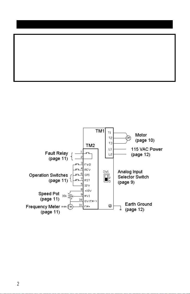
QUICK REFERENCE
IMPORTANT
Read this manual completely and carefully. Pay special attention
to all warnings, cautions, and safety rules. Failure to follow the
instructions could produce safety hazards which could injure
personnel or damage the control, motor, or other equipment. If
you have any doubts about how to connect the control or motor,
refer to the detailed sections of this manual.
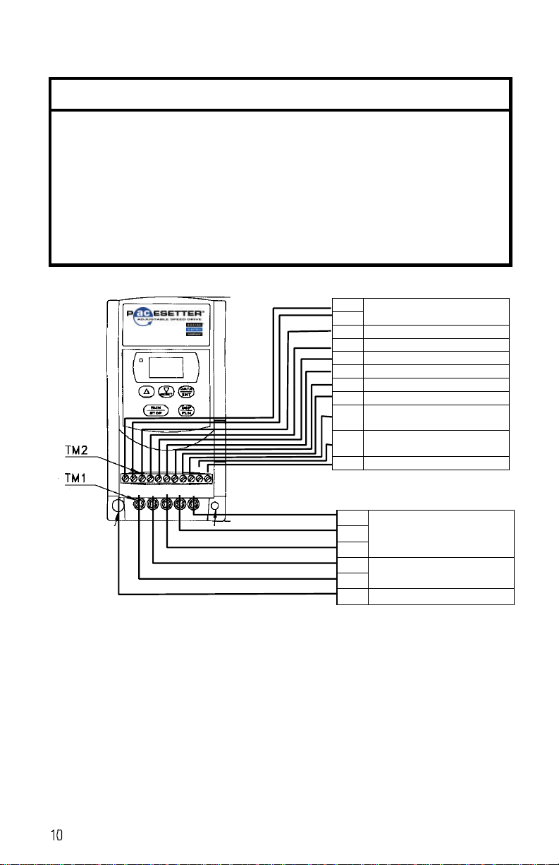
FIGURE 1– Basic Connection Diagram. Refer to noted pages for details.
Function F25 returns all functions to their factory settings.
Artisan Technology Group - Quality Instrumentation ... Guaranteed | (888) 88-SOURCE | www.artisantg.com

TABLE OF CONTENTS
PAGE
QUICK REFERENCE 2
INTRODUCTION 4
PRODUCT SPECIFICATIONS 5
IMPORTANT SAFETY PRECAUTIONS 6
INSTALLATION 7
Step 1 –Examine Before Installation 7
Step 2 –Choose a Suitable Location 7
Step 3 –Mount the Control 8
Step 4 –Preliminary Setup 9
Step 5 –Make Electrical Connections 10
Step 5a –Connect Motor 10
Step 5b –Connect Remote Control Devices (optional) 11
Step 5c –Ground the Inverter 12
Step 5d –Connect Circuit Breaker 12
Step 5e –Connect AC Line 12
Step 6 –Check System Before Starting 13
OPERATION 14
Step 7 –Operate the Control 14
Step 7a –Operate Inverter Using Keypad 14
Step 7b –Operate Inverter Using Remote Devices (optional) 14
Step 7c –Change Other Parameters (optional) 15
Parameter List 15
Parameter Descriptions 17
TROUBLESHOOTING 23
WARRANTY 27
copyright 2000 Bodine Electric Company. All Rights Reserved. Printed in U.S.A.
Artisan Technology Group - Quality Instrumentation ... Guaranteed | (888) 88-SOURCE | www.artisantg.com
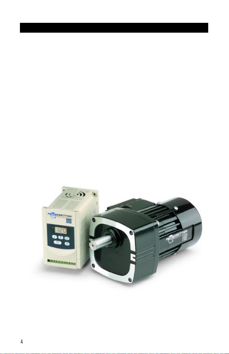
INTRODUCTION
ABOUT THIS MANUAL -This manual contains the basic information
needed to install and operate Bodine PACESETTERTM 115V “NANO”
series inverters, models 2701 and 2703.
This manual does not profess to cover all details or variations in
equipment, nor to provide for every possible contingency associated with
installation, operation, or maintenance. No warranty of fitness for
purpose is expressed or implied. Should further information be desired or
should particular problems arise which are not covered sufficiently for the
user’s purpose, the matter should be referred to the Bodine Electric
Company.
Artisan Technology Group - Quality Instrumentation ... Guaranteed | (888) 88-SOURCE | www.artisantg.com

PRODUCT SPECIFICATIONS
ABOUT THIS PRODUCT -Bodine’s PACESETTERTM “NANO” series
inverter is a PWM type inverter that converts a single phase AC input
voltage into an adjustable frequency three phase AC output voltage.
Since the speed of AC induction motors is proportional to the line
frequency, adjusting the output frequency of the inverter enables
adjustable speed operation of the motor.
Model Number:
2701 2703
Motor HP 1/4 1/2
Motor kW 0.2 0.4
Output Amps 1.4 2.3
Input Volts Single phase 100-120V (+10%-15%) , 50/60Hz (+/-5%)
Output Volts Three phase 200-240V +10%-15% (Input Voltage Max)
Ratings
Weight, Lb (Kg ) 1.5 (0.7) 1.6 (0.72)
Carrier Frequency 1 –16 kHz
Frequency Control Range 0 –200 Hz
Frequency Resolution Digital: 0.1 Hz (0 -99.9Hz); 1 Hz (100~200Hz)
Analog: 1 Hz / 60Hz
Frequency Setting Signal Keypad or external signal (0-10 V, 4–20 mA, 0–20 mA)
Accel / Decel Time 0.1 -999 Seconds
Braking Torque About 20% without external braking resistor (no provisions
for external resistor)
Control
Characteristics
V/F Pattern 3 Patterns each for 50 Hz & 60 Hz
Overload protection 150% for 1 min.
Over-voltage DC voltage > 410V
Under voltage DC voltage < 200V
Momentary
Power Loss 0 -2 seconds: inverter can be restarted by speed search
Stall Prevention Accelerate / Decelerate / Constant speed
Output terminal
short-circuit Electronic circuitry protection
Grounding fault Electronic Circuitry protection
Protection
features
Other function Heat sink temperature protection, Current limit
Indication function 3 character LED display indicates frequency or inverter
parameter or fault record or program version.
Inputs 2 multi-function, PNP type (source)
Output 1 multi-function
Torque control Torque boost level adjustable (manual torque boost)
Operation
Conditions
Other function Decelerate or free run stop, Auto reset, DC braking
frequency / Voltage / Time can be setup by constants.
Ambient Temperature -10 to +40OC
Humidity 0 -95% RH non-condensing.
Vibration Under 1 G (9.8 m/s2)
Enclosure IP20
Dimensions, W x H x D 2.83” x 5.20” x 4.64” (72 mm x 132 mm x 118 mm)
Environmental
Conditions
Mounting Install by mounting screw or DIN rail (Option).
Artisan Technology Group - Quality Instrumentation ... Guaranteed | (888) 88-SOURCE | www.artisantg.com
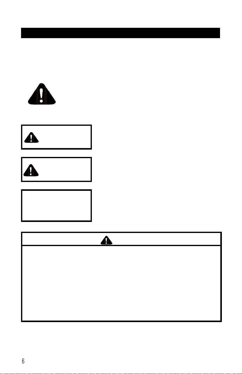
IMPORTANT SAFETY PRECAUTIONS
The AC Drive is a power electronic device. For safety reasons, please
read through this operations manual in detail and observe those
paragraphs with the safety alert symbol.
This is the safety alert symbol. It is used to alert you
to potential personal injury hazards. Obey all safety
messages that follow this symbol to avoid possible
injury or death.
WARNING WARNING indicates a potentially hazardous
situation which, if not avoided, could result in
death or serious injury.
CAUTION CAUTION indicates a potentially hazardous
situation which, if not avoided, may result in
minor or moderate injury.
CAUTION CAUTION used without the safety alert
symbol indicates a potentially hazardous
situation which, if not avoided, may result in
property damage.
WARNING
lDo not touch printed circuit board (PCB) right after
turning off power. Wait until power light turns off.
lDo not attempt to wire circuitry while power is on.
lDo not attempt to examine components and signals on
the PCB while the inverter is operating.
lDo not attempt to disassemble or modify internal
circuitry, wiring, or components of the inverter.
lInverter must be properly grounded using 200V class
type III standard.
Artisan Technology Group - Quality Instrumentation ... Guaranteed | (888) 88-SOURCE | www.artisantg.com

INSTALLATION
This control should only be installed by a qualified person familiar
with its operation and associated hazards. The National Electrical
Code (NEC), local electrical and safety codes, and when
applicable, the Occupational Safety and Health Act (OSHA) should
be observed to reduce hazards to personnel and property.
Step 1. Examine before installation
Check the items you received against your purchase order. The model number is
printed on an adhesive label on the side of the inverter. Carefully examine the control
for shipping damage. Parts errors should be reported to Bodine. Shipping damage
claims should be made to the freight carrier.
CAUTION
Do not connect the AC inverter to the power supply if there
is any sign of damage. Notify the carrier and your distributor
immediately.
Step 2. Choose a Suitable Location
The installation site of the inverter directly impacts the full functionality and lifespan of
the inverter. Because the PACESETTERTM “NANO” series inverter has a ventilated
enclosure (IP 20 rating) and is fan-cooled, the following guidelines should be adhered
to:
lMount the unit vertically so that the fan is on top for better heat dissipation.
lMake sure the temperature around the inverter is between -10OC and +40OC
(avoid locations in direct sunlight or near heating equipment). If inverter is
installed in a control panel, an additional cooling fan may be needed.
lPrevent liquid from dripping into the enclosure vent holes.
lAvoid humid environments.
lAvoid environments with corrosive gas.
lPrevent solid objects, such as dust and metal scraps, from falling into the
enclosure vent holes.
lAvoid locations near radioactive matter or flammable material.
lAvoid locations near equipment that generate electromagnetic interference
(soldering or power machinery).
lAvoid mounting the inverter to a surface that vibrates.
Artisan Technology Group - Quality Instrumentation ... Guaranteed | (888) 88-SOURCE | www.artisantg.com

Step 3 –Mount the Control
Install the inverter onto firm metal base or other inflammable material by inserting
screws through the three 4.5 mm diameter holes in the enclosure base.
DIMENSION Millimeters Inches
A132 5.20
B116 4.57
C130 5.12
D8.2 0.32
E118 4.64
F61 2.40
G72 2.83
FIGURE 2– Mounting dimensions.
Artisan Technology Group - Quality Instrumentation ... Guaranteed | (888) 88-SOURCE | www.artisantg.com
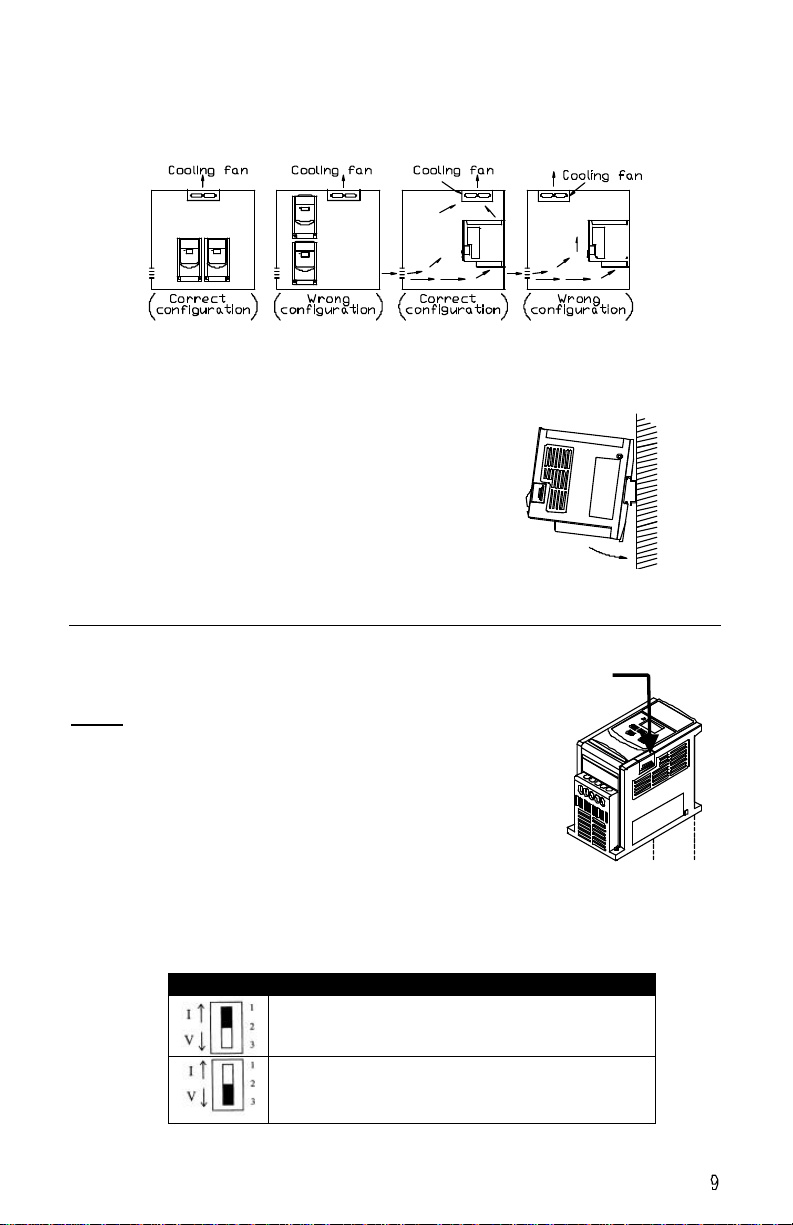
MULTIPLE DRIVES IN ONE PANEL -If several inverters are installed into one control
panel, then observe the guidelines in Fig. 3 in order to maximize the usefulness of the
fan in dissipating heat from the inverter. Inverters should be mounted side by side
and not one above the other.
FIGURE 3– Layout of several inverters inside one panel showing
front view (left) and side view (right).
DIN RAIL MOUNTING – Purchase Bodine’s DIN Rail
Mounting Kit, model 2730, and follow the instructions
that come with it.
FIGURE 4– Inverter installed on DIN Rail.
Step 4 –Preliminary Setup
This step is only required when a remote analog
current signal is to be used to adjust motor speed.
Refer to Fig. 5 and remove the small sliding cover
on the side of the inverter. Inside is a small slide
switch on the printed circuit board. The factory
setting of the switch is for an analog voltage input
and is in the “down” position where “V” is printed on
the circuit board. To configure the drive for an
analog current signal input, slide the switch “up” to
the side where “I” is printed on the circuit board.
FIGURE 6 –Switch settings for analog input signal
SWITCH 1 External signal type
0~10 VDC analog signal ( When Fn11 set to 1 )
0~20mA analog signal (When Fn_11 is set to 1 )
OR
4~20mA analog signal (When Fn_11 is set to 2 )
FIGURE 5 –
Location of
sliding cover
Sliding cover
Artisan Technology Group - Quality Instrumentation ... Guaranteed | (888) 88-SOURCE | www.artisantg.com
Step 5 –Electrical Connections
CAUTION
lThe PCB of the inverter is vulnerable to static electrical
charges. Do not contact the PCB.
lChoose the appropriate power source with correct
voltage settings for the input voltage specification of the
AC inverter.
lDo not use a separate device to switch ON or OFF
motor during operation. Otherwise, the inverter may
experience an over-current breakdown.
1Trip Relay
2
3FORWARD Run Switch
4REVERSE Run Switch
5+12V Terminals 3, 4, 6, 7
6SET SPEED 1 Run Switch
7RESET Switch
8+10V Power for Speed Pot
9Analog Input or Wiper for Speed
Pot
10 0V Common for Analog Input,
Speed Pot, and Analog Output
11 Analog Output
FIGURE 7– Electrical connections with remote inputs and outputs.
Step 5a –Connect the Motor
Connect a 230 VAC three-phase squirrel-cage induction motor with appropriate
ratings for the inverter to the “T1”, “T2”, and “T3” screw terminals on terminal block
TM1. Use a Phillips screwdriver to clamp the stripped motor wires. Tighten to 12 lb-
in. It doesn’t matter which motor wires go to which terminal. If the motor doesn’t
rotate in the desired direction as connected, swap any two of the three motor wires.
T3 230V Three Phase
T2 Motor Connections
T1
L2 115V Single Phase
L1 Power Connections
Ground Screw
Artisan Technology Group - Quality Instrumentation ... Guaranteed | (888) 88-SOURCE | www.artisantg.com

Step 5b –Connect Remote Control Devices (optional)
The drive can be completely controlled by the keypad and it is recommended that
your operate the inverter this way first to verify that it is operating properly by itself
before proceeding to connect external devices to it. For remote operation, the
following devices can be connected to terminal block TM2.
FORWARD RUN/STOP SWITCH & REVERSE RUN/STOP SWITCHES – To enable these
switch inputs, change programmable parameter F10 to “001” (refer to Step 7 for
procedure). Use 20 AWG wire to connect switches with low voltage contacts
between terminals 3 and 5 (FWD) and between 4 and 5 (REV). When the FWD
(or REV) switch is closed, motor will run in forward (or reverse) direction at the
set speed. When the switch is opened, motor will stop. The function of these
switch inputs can be changed with programmable function F03.
PRESET SPEED RUN/STOP SWITCH (SP1) -Use 20 AWG wire to connect a switch
with low voltage contacts to terminals 6 and 5. When switch is closed, and when
motor is commanded to run, motor will run at the speed set by programmable
parameter F08. When switch is opened, motor will run at the speed set by either
the keypad or a remote signal. The function of this switch input can be changed
with programmable function F19.
RESET SWITCH (RESET) -Use 20 AWG wire to connect a switch with low voltage
contacts to screw terminals 7 and 5 on terminal block TM2. Close the switch to
reset the drive after a fault condition. The function of this switch input can be
changed with programmable function F20.
SPEED SIGNAL INPUT (Vin) –To make this input functional, programmable
parameter F11 must be changed to “001” or “002” (refer to Step 7 for
procedure). Use 20 AWG wire to connect a remote analog voltage or current
signal screw terminal 9 on terminal block TM2, using terminal 10 as the signal
common. The drive will accept a 0 –10 VDC, 0 –20 mA, or 4 –20 mA signal
(refer to Step 4 if using a current signal). Alternatively, a speed potentiometer
can be connected to the drive as shown in Fig. 1 with the wiper connected to
terminal 9 and the two end terminals of the speed pot connected to terminals 8
and 10 on the drive.
ANALOG OUTPUT (FM+) –This output produces a 0 –10 VDC signal proportional
to the output frequency of the drive. Use 20 AWG wire to connect a remote
readout or programmable controller to screw terminals 10 and 11 on terminal
block TM2.
FAULT OUTPUT (TRIP RELAY) –This relay output has a contact rating of 250 VAC,
1 Amp or 30 VDC, 1 Amp. Use 20 AWG wire to connect a remote device to
screw terminals 1 and 2 on terminal block TM2. The relay is normally open and
closes when there is a fault condition. This can be used to close the circuit of an
alarm or to signal a programmable controller to shut down.
Artisan Technology Group - Quality Instrumentation ... Guaranteed | (888) 88-SOURCE | www.artisantg.com

Step 5c –Ground the Inverter
The grounding terminal of the inverter must be correctly grounded in compliance with
200V class type three grounding.
lGrounding wire should be wired in accordance to electrical equipment
(AWG) with the length of the grounding wire as short as possible.
lThe grounding wire of the inverter must not be grounded together with
other large current loading (such as soldering machine or large power motor).
They should be grounded separately.
lPrevent ground loops when grounding several inverters together.
FIGURE 8– Grounding multiple drives. The two circuits on the left are correct.
The circuit on the right creates a ground loop and is incorrect.
Step 4h –Connect Circuit Breaker
Connect a 2-pole circuit breaker between terminals L1 & L2 on terminal block TM1
and the 115 VAC single phase supply.
Step 5d –Connect the AC Line
Connect the 115 VAC single-phase power line to the “L1” and “L2” screw terminals
on terminal block TM1. Terminations to the Inverter must be made with either UL
listed field wiring lug kits or UL listed crimp type ring terminals.
Artisan Technology Group - Quality Instrumentation ... Guaranteed | (888) 88-SOURCE | www.artisantg.com

OPERATION
Step 6 –Check System Before Starting
WARNING
lRecheck all connections.
lDo not remove the front cover of the inverter when the
power is ON to avoid personnel injury caused by
electrical shock.
lWhen the automatic restart function is enabled, the
motor and machinery will be restarted automatically.
lDo not attempt to install or remove input or output
connectors of inverter when the power supply is turned
on. Otherwise, the inverter may be damaged due to the
surge peak caused by the insertion or removal.
lDo not attempt to wire circuitry while power is on.
lDo not attempt to examine the components and signals
on the PCB while the inverter operating.
lDo not touch the heat-sink base during operation.
CAUTION
lCheck that motor is securely mounted.
lTest motor unloaded first to verify proper setup.
lCheck all rotating members. Be sure keys, pulleys, etc.
are securely fastened and safety guards are in place.
lCheck for proper mounting and alignment of products,
and verify safe loading on shafts and gears.
lThis product is not provided with over speed protection.
The inverter can be easily operated from a low-speed to
high-speed range. Please reconfirm the operating range
of motor and the machinery you are controlling.
Artisan Technology Group - Quality Instrumentation ... Guaranteed | (888) 88-SOURCE | www.artisantg.com

Step 7: Operate the Control
FIGURE 9– Keypad location and layout
Step 7a –Operate the Inverter using the Keypad
The PACESETTERTM “NANO” series inverter is factory-set for operation using the
pushbutton keypad. Use the following procedure to start the motor and adjust speed.
1) Turn the AC power ON. The LED display will illuminate and show the current
setting for output frequency. The power light just to the left of the LED display will
also illuminate.
2) Press the button labeled “RUN/STOP”. The display will change to show actual
output frequency, which will start at “000” and ramp up to the set frequency.
Simultaneously, the motor will start and accelerate.
3) Press the button labeled “p” to increase the output frequency. The motor will
accelerate until the “p” button is released. Note that the output frequency
changes at a progressively faster rate the longer you hold the button down.
Press the “q” button to decrease the output frequency.
4) Press the button labeled “RUN/STOP” again to stop the motor.
5) If the motor does not start promptly and run smoothly, refer to
“TROUBLESHOOTING”.
Step 7b –Operate the Inverter using remote devices
To enable operation from remote inputs, some of the programmable parameters
need to be changed. Assuming the drive is connected as shown in Fig. 7, use the
following procedure to enable remote control of start/stop operation, speed
adjustment, and direction.
Artisan Technology Group - Quality Instrumentation ... Guaranteed | (888) 88-SOURCE | www.artisantg.com

1. Switch on the AC power.
2. Press the “DSP/FUN” key. The LED display will change from set output
frequency to a function number between “F00” and “F30”.
3. Press either the “q/RESET” key or the “p” key to scroll through the
available function numbers until you reach “F11”. This is the function that
enables remote control of speed adjustment.
4. Press the “DATA/ENT” key. This will change the LED display from the
function number to the current setting of the parameter. The factory setting
for parameter F11 is “000” for keypad control of speed.
5. Press either the “q/RESET” key or the “p” key to change the setting to
either “001” or “002” (see “Speed Control Method (F11)” on page X).
6. Press the “END” key to save the new setting. The LED display will change
to “End” for 1/2 second and then back to the function number.
7. Repeat the above steps, changing the setting of function number F10 to
“001” to enable remote control of direction andstart/stop operation.
8. When finished programming, press the “DSP/FUN” key. The LED display
will change back to the set output frequency.
Step 7c –Change other parameters (optional)
Before changing the programmable parameters, first stop the motor if necessary.
Only acceleration time (F01), deceleration time (F02), motor direction (F04), and
torque compensation (F13) can be changed while motor is running. Use the same
procedure described in Step 7b to change other parameters. The following pages
give a brief description of each parameter. To clear the inverter of all changes and
return it to the factory settings, change function F25 to “020”.
Parameter List, Functions F01 –F11
Function Description Range Factory setting
F01 Acceleration time 00.1 –999 seconds 05.0
F02 Deceleration time 00.1 –999 seconds 05.0
F03 External operation mode 000: FWD/Stop, REV/Stop
001: Run/Stop, FWD/ REV 000
F04 Direction selection 000: Forward
001: Reverse 000
F05 V/F pattern setting 001: 50 Hz General application
002: 50 Hz High starting torque
003: 50 Hz Variable torque
004: 60 Hz General application
005: 60 Hz High starting torque
006: 60 Hz Variable torque
004
F06 Maximum frequency 01.0 -200 Hertz 60.0
F07 Minimum frequency 00.0 -200 Hertz 00.0
F08 Preset speed 1 (SP1) 01.0 -200 Hertz 10.0
F09 JOG frequency 01.0 –200 Hertz 06.0
F10 Operation control method 000:keypad
001: external terminal 000
F11 Speed control method 000: keypad
001: external signal (0~10v/0~20mA )
002: external signal ( 4~20mA )
000
Artisan Technology Group - Quality Instrumentation ... Guaranteed | (888) 88-SOURCE | www.artisantg.com

Paramter List, Functions F12 –F27
Function Description Range Factory setting
F12 Switching frequency 001: 4 kHz 006: 10 kHz
002: 5 kHz 007: 12 kHz
003: 6 kHz 008: 14.4 kHz
004: 7.2 kHz 009: 15 kHz
005: 8 kHz 010: 16 kHz
005
F13 Torque boost adjustment 00.0 -10.0% 00.0
F14 Stopping method 000: decelerate stop
001: free run stop 000
F15 Braking time 00.0 -25.5 seconds 00.5
F16 Braking starting frequency 01.0 -10.0 Hertz 01.5
F17 Braking level 00.0 -20.0% 08.0
F18 Currentlimit 000 -200% 100
F19 Input terminal 6 function 001: Jog
002: SP1
003: Emergency stop
004: External Base Block
005. Reset
006: SP2
002
F20 Input terminal 7 function 001: Jog
002: SP1
003: Emergency stop
004: External Base Block
005. Reset
006: SP2
005
F21 Output terminal function 001: Operating
002: Frequency reached
003: Fault
003
F22 Reverse enable 000: REV command enabled
001: REV command disabled 000
F23 Auto restart enable 000: Auto restart enabled
001: Auto restart disabled 000
F24 Auto restart times 000 –005 times 000
F25 Restore factory settings 010: Restore to 50Hz settings
020: Restore to 60Hz settings 000
F26 Preset speed 2 (SP2) 01.0 -200 Hertz 020
F27 Preset speed 3 (SP3) 01.0 -200 Hertz 030
Artisan Technology Group - Quality Instrumentation ... Guaranteed | (888) 88-SOURCE | www.artisantg.com

Description of Programmable Functions
F01: Acceleration Time
Function F01 can be changed to adjust the acceleration time from the default
setting of 5.0 seconds to any time between 0.1 and 999 seconds.
Set Frequency
Acceleration time = F01 x
60 Hz
F02: Deceleration Time
Function F02 can be changed to adjust the deceleration time from the default
setting of 5.0 seconds to any time between 0.1 and 999 seconds.
SetFrequency
Deceleration time = F02 x
60Hz
F03: Start / Stop Control from TM2
Function F03 sets the function of input terminals 3 and 4, provided that function
F10 is set at “001” for external control operation. The default setting of F03 is
“000”, which configures input terminal 3 for a “Forward/Stop” switch (close to
run forward, open to stop) and input terminal 4 for a “Reverse/Stop” switch
(close to run reverse, open to stop). The alternate setting of F03 is “001”, which
configures input terminal 3 for a “Run/Stop” switch (close to run, open to stop)
and input terminal 4 for a “Forward/Reverse” switch (close for forward direction,
open for reverse).
F04: Direction Selection
Although there is no Forward/Reverse push button on the digital control panel, it
is possible to change motor direction without changing the motor connection by
changing function F04. The factory setting is “000” for forward direction.
Changing F04 to “001” will result in reverse direction. NOTE: When F22 =
“001”, reverse is disabled and F04 can not be set to “001”. If it is, the keypad
indication will display the error message “LOC”.
F05: V/F Pattern Setting
Function F05 can be changed from its factory setting of “004” to any number
between “001” and “006”. Settings “001” through “003” are to be used only
when the inverter is configured for 50 Hz input power. Settings “004” through
“006” are to be used only when the inverter is configured for 60 Hz input power.
The three different settings for each input frequency control the ratio of output
voltage to output frequency. The factory setting of “004” with 60 Hz input power
produces a constant volts/frequency ratio between output frequencies of 0 to 60
Hz (above 60 Hz, the output voltage is fixed). The alternate settings either
boost the voltage at lower frequencies for higher starting torque (F05 = “002” or
“005”) or reduce the voltage at lower frequencies for applications where the
torque increases with speed, like a fan (F05 = “003” or “006”). See Fig. 10.
Artisan Technology Group - Quality Instrumentation ... Guaranteed | (888) 88-SOURCE | www.artisantg.com

FIGURE 10 – Six different V/F settings.
V/F Pattern for F05 = 001
(50 Hz General Application)
0%
20%
40%
60%
80%
100%
120%
0.1 1 10 100 1000
Output Frequency, Hz
Volts,% of max.
V/F Pattern for F05 = 002
(50 Hz High Starting Torque)
0%
20%
40%
60%
80%
100%
120%
0.1 110 100 1000
Output Frequency, Hz
Volts,% of max.
V/F Pattern for F05 = 003
(50 Hz Variable Torque)
0%
20%
40%
60%
80%
100%
120%
0.1 1 10 100 1000
Output Frequency, Hz
Volts,% of max.
V/F Pattern for F05 = 004
(60 Hz General Application)
0%
20%
40%
60%
80%
100%
120%
0.1 1 10 100 1000
Output Frequency, Hz
Voltage, % of max.
V/F Pattern for F05 = 005
(60 Hz High Starting Torque)
0%
20%
40%
60%
80%
100%
120%
0.1 1 10 100 1000
Output Frequency, Hz
Voltage, % of max.
V/F Pattern for F05 = 006
(60 Hz Variable Torque)
0%
20%
40%
60%
80%
100%
120%
0.1 110 100 1000
Output Frequency, Hz
Voltage,% of max.
F06: Upper Frequency Limit
Use function F06 to change the upper frequency limit, and hence the maximum
motor speed limit, by changing F06 from the factory setting of “60.0” (60 Hz) to
any number between “01.0” and “200” in increments of 0.1 Hz up to 100 Hz and
increments of 1 Hz after that.
F07: Lower Frequency Limit
Use function F07 to change the lower frequency limit, and hence the minimum
motor speed limit, by changing F07 from the factory setting of “00.0” (0.0 Hz) to
any number between “00.0” and “200” in increments of 0.1 Hz up to 100 Hz and
increments of 1 Hz after that. If F07 > “00.0” and the frequency command<F07,
the inverter will output according to F07 setting.
F08: Preset Speed 1 (SP1) Frequency
Change the frequency of the SP1 input by changing F08 from the factory setting
of “10.0” (10 Hz) to any number between “01.0” and “200” in increments of 0.1
Hz up to 100 Hz and increments of 1 Hz after that. When F19 or F20 = “002”
and the corresponding input terminal is ON, the inverter operates at the
frequency set by F08. The priority of reading frequency setting is: Jog setting g
SP1 setting gkeypad setting or external frequency signal
F09: Jog Speed Reference
Use function F09 to change the frequency of the JOG input by changing F09
from the factory setting of “06.0” (6 Hz) to any number between “01.0” and “200”
in increments of 0.1 Hz up to 100 Hz and increments of 1 Hz after that. When
F19 or F20 = “001” and the corresponding input terminal is ON, the inverter
operates at the frequency set by F09. The priority of reading frequency setting
is: Jog setting gSP1 setting gkeypad setting or external frequency signal
Artisan Technology Group - Quality Instrumentation ... Guaranteed | (888) 88-SOURCE | www.artisantg.com
F10: Start / Stop Control Method
Use function F10 to select between the keypad (F10 = “000”) or an external
signal (F10 = “001”) for run/stop instruction. The factory setting of F10 is “000”.
When F10 = “001”, emergency stop on the keypad is enabled.
F11: Frequency Command Selection
Use function F11 to select where the frequency command comes from. The
factory setting of F11 is “000”, so that the frequency command comes from the
keypad. Alternate settings allow the frequency command to come from an
analog signal on TM2, either 0 ~ 10V or 0 -20mA (F11 = “001”), or 4 -20mA
(F11 = “002”).
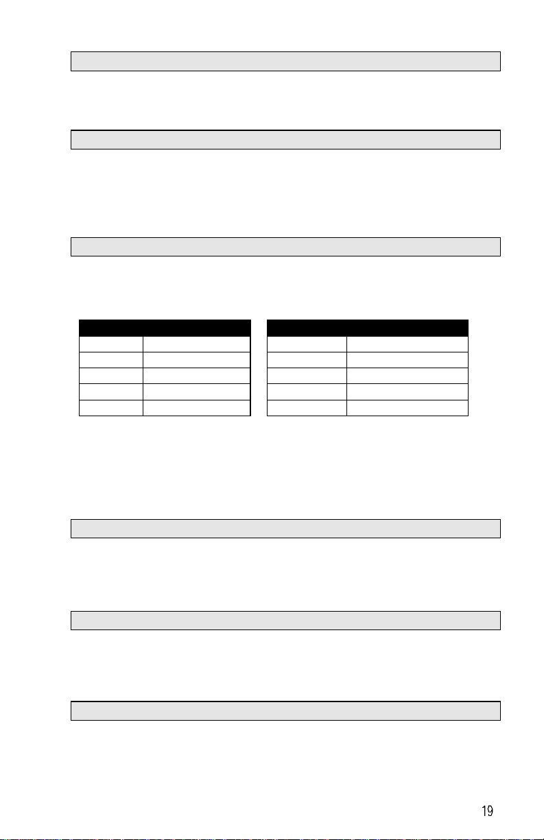
F12: Carrier Frequency
Use function F12 to change the PWM switching frequency from the factory
setting of 8 kHz (F12 = “005”) to any one of the settings listed in Fig. 11.
FIGURE 11 – Ten different PWM switching frequencies to choose from.
F12 carrier frequency F12 carrier frequency
001 4 kHz 006 10 kHz
002 5 kHz 007 12 kHz
003 6 kHz 008 14.4 kHz
004 7.2 kHz 009 15 kHz
005 8 kHz 010 16 kHz
If F12 = 007 thru 010, the inverter will run hotter than normal. Additional cooling
may be required or a motor smaller than the normal rating should be used.
Although IGBT TYPE inverters can provide a low audible noise environment
during operation, it is possible that high frequency switching may interfere with
external electronic components (or other controllers).
F13: Torque compensation gain
Function F13 changes torque compensation gain from the factory setting of
0.0% (“000”) to any number between 0.0% (“000”) and 10% (“010”). The
voltage at the B and C points on the V/F patterns (refer to F05 description) are
boosted by the percentage set by F13 to enhance output torque.
F14: Stopping Mode
Function F14 changes the stopping method. If F14 = “000” (factory setting) and
the inverter receives a stop instruction, it decelerates to the frequency set by
F16 by applying the output voltage level set by F17 for the time duration set by
F15. If F14 = “001”, the motor coasts to a stop.
F15: DC Braking Time
Function F15 changes DC braking time from the factory setting of 0.5 seconds
to any number between 0.0 and 25.5 in increments of 0.1 second.
Artisan Technology Group - Quality Instrumentation ... Guaranteed | (888) 88-SOURCE | www.artisantg.com
This manual suits for next models
1
Table of contents
Other Bodine Engine manuals


Popular Engine manuals by other brands

Ventus
Ventus BOW5512D Operation manual and installation instructions

Aqua-Scope
Aqua-Scope KFRLWE01 User and installation manual

LZ design
LZ design FES-DG-M100 manual

Crestron
Crestron QMT CSM-QMTDC Programming guide

Leroy-Somer
Leroy-Somer HPM 250 Installation and Maintenance

wsm
wsm 70mm STROKE SERIES Workshop manual


