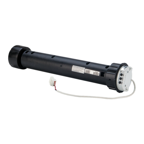
LED Diagnostics
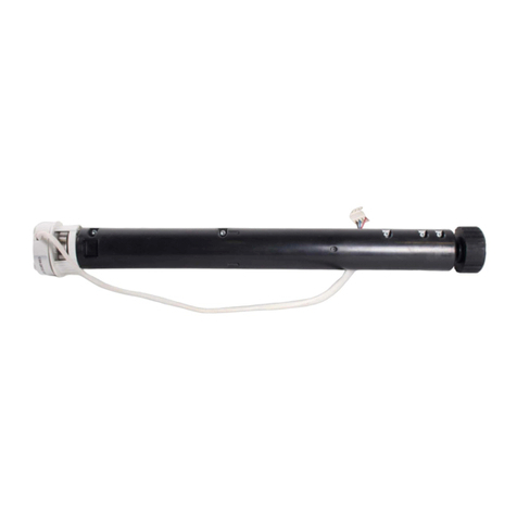
The LED ashes to provide a visual reference that the motor is operating normally or if it is
in an error state
Normal Operation
The following table provides a list of possible LED patterns encountered during normal
operation. All LEDs extinguish after 1 minute of inactivity if there are no errors to report.
LED Patterns
LED PATTERN LED COLOR OPERATING MODE
Two fast ashes, then
pause (1/8-second on,
1/8-second off, 1/8-second
on, 5/8-second off)
Blue A rmware upgrade over the Cresnet®
network is in progress.
Slow ash (1/2-second on,
1/2-second off)
Blue The motor’s internal rmware upgrade is
in progress.
Solid Blue The motor is in Bootloader mode.
Fast ash (1/4-second on,
1/4-second off)
White The motor is in Identify mode.
Slow ash (1/2-second on,
1/2-second off)
Green The motor is moving from a local button
press.
Solid Green The motor is communicating with the
control system program.
Slow ash (1/2-second on,
1/2-second off)
Red The motor is not communicating with the
control system.
Error State
Crestron CSM-QMTDC motors display error codes using the red LED on the interface. The
LED ashes a pattern to indicate the error.
For example, when a 3-3 LED ash pattern occurs, the LED ashes three times, pauses
for 1 second, ashes three times, pauses for 5 seconds, and then repeats until the error is
corrected. When a 2-1 LED ash pattern occurs, the LED ashes two times, pauses for
1 second, ashes once, pauses for 5 seconds, and then repeats this code until the error is
corrected.
The ash patterns are listed in the following table. Refer to the “Troubleshooting” section
for possible corrections.
LED Blinking Patterns
LED PATTERN ERROR STATE
Error code 3-1 The motor limits are not set.
Error code 3-3 An obstruction is blocking the shade fabric from moving freely.
Error code 3-4 A motor over-current error exists. Check for obstacles or any sources
of excessive friction.
Error code 3-5 A motor duty-cycle error exists. Reduce the operating duty cycle of
the motor to correct the error.
Error code 3-6 There is a communications error between the motor and Cresnet or
inNET EX control board.
LED PATTERN ERROR STATE
Error code 2-1 There is no trafc on the network. Check to ensure that proper
Cresnet wiring is maintained, or for inNET EX devices, ensure that
the motor is connected to a gateway.
Error code 2-2 The motor is not being polled by the control system. Ensure that the
Net ID matches the control system program and that the program is
running on the control system.
Troubleshooting
The following table provides corrective action for possible trouble situations. If further
assistance is required, please contact a Crestron customer service representative.
Crestron CSM-QMTDC Motor Troubleshooting
TROUBLE POSSIBLE CAUSE(S) ACTION
The motor cannot be
controlled, and all of the
LEDs are off.
There is no power provided
to the motor.
Check the power
connections between the
power supply and motor.
The power connection
is reversed between the
motor and the power
supply.
Ensure that the power
connection to the motor is
not reversed.
The motor moves in the
opposite direction.
The motor direction is
reversed.
Reverse the direction of the
motor.
The motor intermittently
stops working.
The motor is exceeding its
maximum duty cycle.
Reduce the duty cycle of
the motor operation.
The motor is encountering
an obstacle or excessive
friction, which is causing it
to stop.
Verify that all components
are aligned and running
smoothly.
The load on the motor is
exceeding its maximum
rating.
Verify that the fabric weight
and tube size do not
exceed the rating for the
motor.
The LED is blue. The motor is stuck in the
bootloader.
Reload rmware to the
motor.
For Models CSM-QMTDC-256-2-EX/CSM-QMTDC-250-4-EX/CSM-QMTDC-163-1-EX/CSM-
QMTDC-250-2-EX/ CSM-QMTDC-275-4-EX
Industry Canada (IC) Compliance Statement
This device complies with Industry Canada licence-exempt RSS standard(s). Operation is subject
to the following two conditions: (1) this device may not cause interference, and (2) this device must
accept any interference, including interference that may cause undesired operation of the device.
Under Industry Canada regulations, this radio transmitter may only operate using an antenna of
a type and maximum (or lesser) gain approved for the transmitter by Industry Canada. To reduce
potential radio interference to other users, the antenna type and its gain should be so chosen that
the equivalent isotropically radiated power (e.i.r.p.) is not more than that necessary for successful
communication.
Industrie Canada (IC) Déclaration de conformité
Le présent appareil est conforme aux CNR d’Industrie Canada applicables aux appareils radio
exempts de licence. L’exploitation est autorisée aux deux conditions suivantes : (1) l’appareil ne doit
pas produire de brouillage, et (2) l’utilisateur de l’appareil doit accepter tout brouillage radioélectrique
subi, même si le brouillage est susceptible d’en compromettre le fonctionnement. Conformément à la
réglementation d’Industrie Canada, le présent émetteur radio peut fonctionner avec une antenne d’un
type et d’un gain maximal (ou inférieur) approuvé pour l’émetteur par Industrie Canada. Dans le but
de réduire les risques de brouillage radioélectrique à l’intention des autres utilisateurs, il faut choisir
le type d’antenne et son gain de sorte que la puissance isotrope rayonnée équivalente (p.i.r.e.) ne
dépasse pas l’intensité nécessaire à l’établissement d’une communication satisfaisante.
To satisfy RF exposure requirements, this device and its antenna must operate with a separation
distance of at least 20 centimeters from all persons and must not be colocated or operating in
conjunction with any other antenna or transmitter.
For All Models
Federal Communications Commission (FCC) Compliance Statement
This device complies with part 15 of the FCC Rules. Operation is subject to the following conditions:
(1) This device may not cause harmful interference and (2) this device must accept any interference
received, including interference that may cause undesired operation.
CAUTION: Changes or modications not expressly approved by the manufacturer responsible for
compliance could void the user’s authority to operate the equipment.
NOTE: This equipment has been tested and found to comply with the limits for a Class B digital
device, pursuant to part 15 of the FCC Rules. These limits are designed to provide reasonable
protection against harmful interference in a residential installation. This equipment generates,
uses and can radiate radio frequency energy and, if not installed and used in accordance with the
instructions, may cause harmful interference to radio communications. However, there is no guarantee
that interference will not occur in a particular installation. If this equipment does cause harmful
interference to radio or television reception, which can be determined by turning the equipment off
and on, the user is encouraged to try to correct the interference by one or more of the following
measures:
• Reorient or relocate the receiving antenna.
• Increase the separation between the equipment and receiver.
• Connect the equipment into an outlet on a circuit different from that to which the receiver is
connected.
• Consult the dealer or an experienced radio/TV technician for help.
For Models CSM-QMTDC-256-2-CN/CSM-QMTDC-250-4-CN/CSM-QMTDC-163-1-CN/CSM-
QMTDC-250-2-CN/ CSM-QMTD-275-4-CN
Industry Canada (IC) Compliance Statement:
CAN ICES-3(B)/NMB-3(B)
The product warranty can be found at www.crestron.com/warranty.
The specic patents that cover Crestron products are listed at www.crestron.com/legal/patents.
Certain Crestron products contain open source software. For specic information, please visit
www.crestron.com/opensource.
Crestron, the Crestron logo, Cresnet, Crestron Toolbox, inNET EX, and QMT are either trademarks
or registered trademarks of Crestron Electronics, Inc. in the United States and/or other countries.
Other trademarks, registered trademarks, and trade names may be used in this document to refer to
either the entities claiming the marks and names or their products. Crestron disclaims any proprietary
interest in the marks and names of others. Crestron is not responsible for errors in typography or
photography.
This document was written by the Technical Publications department at Crestron.
©2017 Crestron Electronics, Inc.
Crestron Electronics, Inc. Programming Guide - DOC. 7437EA
15 Volvo Drive, Rockleigh, NJ 07647 (2041118)
Tel: 888.CRESTRON 12.17
Fax: 201.767.7576 Specications subject to
www.crestron.com change without notice.
