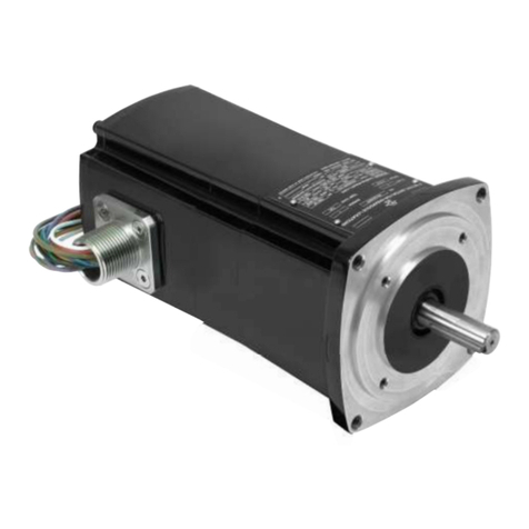
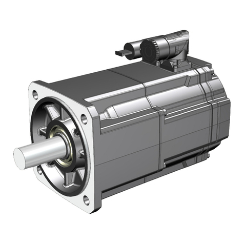
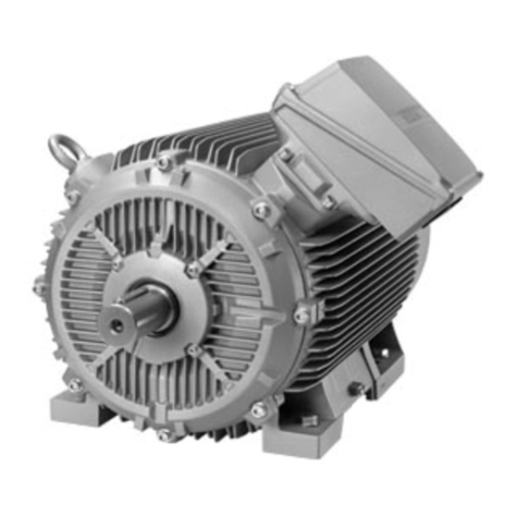
Bodine 33A User manual

Inspecting and Replacing Brushes in a Bodine Type 33A, 42A, and 32A motor or gearmotor. Lit P/ 07481063A. © Bodine 2007 Page 1 of 8
Inspecting and Replacing Brushes in Bodine Type
33A, 42A, and 32A (PMDC) Motors or Gearmotors
The permanent magnet DC (PMDC) motors and gearmotors manufactured by
Bodine Electric Company are unique compared to other DC motors and
gearmotors in many ways. This is because the primary objectives in the design
of all Bodine products are long life, quiet operation, and no lubricant leakage.
With regard to long brush life, the Bodine type
33A, 42A, and 32A motors and gearmotors
employ a unique method of maintaining a
constant force on the brushes inside the motor.
A roll-type spring is used instead of the more
common coiled spring. The roll-type spring puts
a constant force on the brushes even as they
wear and get shorter. By contrast, the force
exerted by a coiled spring diminishes as the
brushes get shorter and the spring approaches its
uncompressed length. Reduced force on the
brushes can cause them to “hop” on the
commutator and wear faster. The roll-type
spring is a superior design.
Installing the roll-type springs correctly is
critical in order to obtain optimal performance
from your Bodine motor or gearmotor. Incorrect
installation can cause brushes to wear faster, or
ultimately could damage the product.
By following these instructions when inspecting and replacing the brushes in a
Bodine type 33A, 42A, or 32A motor or gearmotor, the user can be assured of
long brush life, and desired motor or gearmotor performance.
TOOLS NEEDED:
Large slotted
tip screwdriver
Medium size
slotted tip
screwdriver
Small
screwdriver with
any type of tip
Pair of long nose
pliers
Safety glasses
Roll-type Spring
Coiled Spring
851-628 Rev. A

2
STEP #1 – Disconnect Power
Disconnect the motor wires from the power source before working on the motor.
The motor or gearmotor should be cooled off to room temperature.
WARNING
Failure to disconnect the motor wires from the
power source before inspecting or replacing
brushes can result in personal injury.
STEP #2 – Remove Two Brush Caps
Refer to Figure 1 for the location of the two brush caps. The plastic brush caps
are held in place with screw threads. Unscrew the brush caps using the largest
possible slotted screwdriver tip and remove them.
CAUTION
The brush caps are made of plastic and are installed
tightly. Using a small screwdriver to remove them
will damage the slot.
STEP #3 – Remove Brush Springs
After the brush caps are removed from each side
of the motor, the brush box assemblies can be seen
inside each of the two openings. The brushes are
retained by constant-force, roll-type springs. The
springs must be removed before the brushes can
be removed. To remove a spring, first locate the
flat part of the spring, which points outward (see
Figure 3). WARNING: Wear safety glasses!
Figure 3
–
Flat part of spring.
Brush Caps
(one on each side)
Figure 1 – Location of the Brush Caps
Figure 2
–
Use a large screwdriver.
Flat part of spring

3
Then grasp the flat part of the spring with a pair of long nose pliers (Figure 4).
There is a hook at the other end of the spring (see Figure 5) that must be
disengaged from the bottom edge of the brush box. Press inward on the spring
to unhook the spring. The spring may “pop” out. Otherwise, pull it out. Repeat
the procedure for the spring on the other side of the motor or gearmotor.
STEP #4 – Inspect Brushes
It is not necessary to disconnect the brush wires just to inspect the brushes.
Insert a small screwdriver under the brush wire and pull the brush out of the
brush box. With the brush wire still connected to the brush box, measure the
length of the brush from the point where the wire merges with the brush to the
end of the brush that contacts the commutator inside the motor.
Figure 6 – Pull brush out. Figure 7 – Leave brush connected.
Figure 4
–
Grasp spring with pliers.
Figure 5
–
Push in; pull out.
Hooks

4
Brush wear rate varies, depending
on the individual application’s duty
cycle, and should be inspected at
frequent intervals to determine an
appropriate inspection schedule.
Brushes should be replaced before
the total length is less than .375 inch
(9.5 mm). See Figure 8.
Repeat the inspection procedure for
the other brush.
If new brushes are required, record
the motor type and serial number
from the motor nameplate. Contact
your supplier, any Authorized
Bodine Distributor, or our Service
Department. You will find more
information on how to contact us on
Bodine Electric’s website at:
www.bodine-electric.com
STEP #5 – Remove Old Brushes
Using a medium size slotted screwdriver, loosen the screw that holds the brush
wire by four turns (do not remove). Slide the brush wire terminal out from
under the holding screw head and remove the brush.
Repeat this procedure for the other brush.
STEP #6 – Clean Out Brush Dust
Excessive carbon dust will accumulate inside the motor endshield over time and
should be removed periodically to allow normal operation. Partial disassembly
and cleaning is best. However, carefully applying compressed air alternately
through each of the open brush cap holes may provide adequate cleaning. Do
not use solvents as they may damage non-metallic parts and adversely affect
subsequent brush commutation.
STEP #7 – Install New Brushes
Position the terminal of the new brush fully under the screw head on the brush
box and tighten the screw (Figure 9). Next, observe that there is a slot in the
base of each brush box. Position and insert each brush so that the wire attached
to the brush aligns with the slot in the brush box and can “feed” into the brush
box slot as the brush wears down. The brush wire must be capable of moving
freely in the slot. See Figure 10.
Figure 8 – Measure brush.
>
.375” (9.5 )

5
CAUTION
Make sure the brush wire is capable of moving
freely in the slot in the brush box. Failure to do
so may cause the brush to get stuck in the brush
box and will result in poor motor performance.
WARNING
The motor frame ground wire is connected to
the same screw as one of the brush wires. If the
ground wire was removed, make certain that it
is securely reconnected. Failure to do so may
result in personal injury.
STEP #8 – Inspect Springs
Inspect the springs to make sure they weren’t damaged during their removal. If
they are uncoiled or otherwise damaged, record the product type and serial
number from the motor nameplate. Contact your supplier, any Authorized
Bodine Distributor, or our Service Department. You will find more information
on how to contact Bodine Electric at: www.bodine-electric.com
Make sure brush
wire is in slot
BAD (uncoiled) GOOD
Figure 9
–
Connect brush terminal.
Figure 10
–
Put brush wire in slot.
Figure 11
–
Comparison of bad and good springs.

6
STEP #9 – Install Springs
Correct replacement of brush springs is critical to assure optimum drive
performance. Grasp the tip of the spring bracket such that the coil of the roll-
type spring will be on the “brush side” of the brush box, and resting on the brush
when the brush spring is brought up to the brush box (see Figure 12). Push the
spring bracket slowly into its slot while letting its two attaching hooks slide on
the wall of the brush box. Stop, but do not release the spring bracket when its
hooks slip around the edge of the brush box. While still grasping the spring
bracket with the pliers, slowly bring the bracket back out of the brush box until
the hooks latch around the edge of the brush box. Release the pliers. If the
spring bracket is properly seated it will be lying flat against the brush box wall.
If it is “cocked” to one side, it is improperly seated – release the spring and
reassemble it again. Important: As a final check, apply slight pressure on the
spring bracket in the direction away from the brush with the tip of the pliers –
the bracket not “popping” out indicates proper latching of the hooks. See Figure
14 for additional illustration of how the spring should be installed in the brush
box.
CAUTION
Make certain that the coil of the springs is
centered directly on the brushes (see Figure 13).
Failure to do so will result in poor motor
performance.
Figure 12
–
Grasp spring.
Figure 13
–
Coil centered directly over brush.

7
STEP #10 - Install Brush Caps
If the brush caps were damaged during their removal and need to be replaced,
record the motor type and serial number from the motor nameplate. Contact
your supplier, any Authorized Bodine Distributor, or our Service Department.
You can find more information on how to contact Bodine Electric at:
www.bodine-electric.com
Screw brush caps back into the end shield using largest possible screwdriver.
STEP #11 – Connect to Power
Reconnect the drive to the power source, and test for proper operation. New
brushes may be seated by running the motor or gearmotor in at no load. Proper
seating is required for lowest brush noise level.
All information and data contained in this document are subject to change
without notice. Please contact our Technical Support staff in Chicago, or an
Authorized Bodine Service Center, if you have any questions about these
instructions. Copyright Bodine Electric Company 2007. All rights reserved.
Figure 14
–
Drawing of how spring should be installed in brush box.

8
Bodine Electric Co pany
2500 W. Bradley Place
Chicago, Illinois 60618 U.S.A.
TEL: (773) 478-3515
FAX: (773) 478-3232
www.bodine-electric.com
Inspecting and Replacing Brushes in a Bodine Type 33A, 42A, and 32A motor or gearmotor. Lit. P/ 07481063A1. © Bodine 2007 Page 8 of 8
851-628 Rev. A
This manual suits for next models
2
Table of contents
Other Bodine Engine manuals
Popular Engine manuals by other brands
SOMFY
SOMFY J4 RTS Installer's guide
Briggs & Stratton
Briggs & Stratton Vanguard 130000 Operator's manual
Yamaha
Yamaha EF2200iS owner's manual
Perkins
Perkins 1106D Operation and maintenance manual

Detroit Diesel
Detroit Diesel MBE4000 Application and installation guide
Fluidampr
Fluidampr 760121 installation instructions
