Bodine ELI Series User manual

Installation and Operation Instructions
ELI-S-100
WITH AUTO-DIMMING FEATURE
ELI SERIES EMERGENCY LIGHTING INVERTERS
READ AND FOLLOW ALL SAFETY INSTRUCTIONS
! IMPORTANT SAFEGUARDS ! WHEN USING ELECTRICAL EQUIPMENT, BASIC SAFETY
PRECAUTIONS SHOULD ALWAYS BE FOLLOWED,
INCLUDING THE FOLLOWING:
SAVE THESE INSTRUCTIONS
Pb
1. Caution:
• High voltage will be present on the output wires and terminals if batteries are installed and inverter
connector is joined or if AC power is supplied to the switched and unswitched terminal.
• Ensure input and output primary wiring connections are made to the proper terminals. Damage to product
may occur if miswired.
• Ensure load voltage requirements (120 or 277 Vac) match the output ratings of this product or damage to
the load devices may occur.
2. This product is suitable for use in dry and damp locations where the ambient temperature is 0°C through
40°C, depending on load. See output ratings on product label for details. This product is not suitable for
heated air outlets and wet or hazardous locations.
3. Make sure all connections are in accordance with the National Electrical Code or Canadian Electrical Code
and any local regulations.
4. To reduce the risk of electric shock, disconnect both the normal and emergency power supplies and the
inverter connector of the emergency lighting inverter before servicing.
5. Do not install near gas or electric heaters.
6. An unswitched AC power source is required. The AC voltage rating of this equipment is specified on the
product label. Do not connect equipment to any other voltage.
7. Equipment should be mounted securely in locations and at heights where it will not be readily subjected to
tampering by unauthorized personnel.
8. The use of accessory equipment and replacement parts not recommended by the manufacturer may cause an
unsafe condition.
9. Do not use this equipment for other than its intended purposes.
10. The battery is field replaceable. Contact manufacturer for information on replacement. Use caution when
replacing battery. Dispose of the battery properly. Do not incinerate.
THIS PRODUCT INCLUDES RECHARGEABLE LEAD-ACID BATTERIES.
THE BATTERIES MUST BE RECYCLED OR DISPOSED OF PROPERLY.
Bodine © 2018 Signify Holding. All rights reserved.
236 Mt. Pleasant Rd. • Collierville, TN USA 38017-2752 • Tech Support 888-263-4638 • Fax 901-853-5009 • www.bodine.com
81000092
11/27/18
INSTALLATION
WARNING: TO PREVENT HIGH VOLTAGE FROM BEING PRESENT ON THE AC OUTPUT LEADS
(HOT AND NEUTRAL) PRIOR TO INSTALLATION,INVERTER CONNECTOR MUST BE OPEN.JOIN INVERTER
CONNECTOR INSIDE THE CASE AFTER INSTALLATION IS COMPLETE AND AC POWER IS SUPPLIED.
NOTE: Make sure the inverter connector is closed before screwing the front cover to the case.
STEP #1 INSTALLING THE EMERGENCY LIGHTING INVERTER
> Remove front cover and any packing material inside the unit housing that may have been used for shipping
purposes.
> Secure housing to the mounting surface through the keyhole knockouts using mounting hardware (not supplied).
This hardware must be appropriate to hold the unit weight of 25 lbs with the batteries installed.
> Remove the knockouts to install input and output wiring conduit fittings.
> Extend AC supply, output load wiring, and optional control wiring into the equipment enclosure using appropriate
wiring hardware and methods. Use copper wire only.
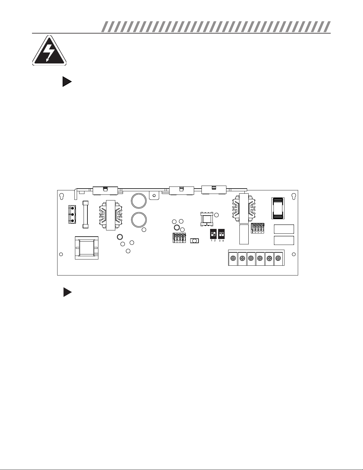
> Illustration 1 details the locations of the various wiring terminals and switch locations needed for the remainder of
the installation. Reference Illustration 1 for Steps through 2 through 6.
ILLUSTRATION 1
INSTALLATION QUICK REFERENCE GUIDE
STEP #2 WIRING THE EMERGENCY LIGHTING INVERTER’S PRIMARY POWER CONNECTIONS
NOTE: Make sure all connections are in accordance with the National Electrical Code, Canadian Electrical Code and
any local regulations.
Reference Illustration 2 when making the following wiring connections.
> Connect the Load Common lead to screw terminal TB3 –"LOAD NEUTRAL"
> Connect the Load Hot lead to screw terminal TB3 –"LOAD Hot"
> Connect the Emergency Lighting Inverter to ground using screw terminal TB3 -"SAFETY GROUND"
> Connect the AC Power Source Common to screw terminal TB3 –"NEUTRAL"
> Connect the Unswitched Hot to screw terminal TB3 -CONSTANT LINE HOT"
Screw terminal "TB3 -SWITCH LINE HOT" is the means of powering the load luminaires in normal mode. If a wall switch is
the local control means, this switched hot must be connected in order to power the load when AC power is present. If no
wall switch is used, and the load luminaires are controlled by the same circuit breaker that is powering the unswitched
hot,"TB3 -SWITCH LINE HOT" can be jumpered to "TB3 -CONSTANT LINE HOT".
2
TB3
K2
K1
K3
J1
J2
L40 1
L40 5
F201
J8
T302
C216
L601
C220
C611
C618
C312
C311
C803
L802 C802
T301
C804
S701 S702
RED
WHT
BRN
VIO
LOAD
T201
CONSTANT
LINE HOT
SWITCH
LINE HOT
DIM-OUT
DIM+OUT
DIM-IN
DIM+IN
NEUTRAL
SAFETY
GROUND
LOAD
HOT
LOAD
NEUTRAL

BATTERY INSTALLATION
This product is provided with two lead-acid batteries, which must be mechanically secured inside the enclosure using the
battery bracket provided. They must then be wired using the battery connection wires also provided. Refer to Illustrations
3 and 4 for installation.
Install the batteries as shown. With the unit secured to the mounting surface, place the batteries into the enclosure as
shown in Illustration 3. Insert the battery bracket on the battery bracket stud, ensuring the bracket is placed against the
batteries. Slide the ring terminal of the grounding wire over the battery bracket stud. Securely fasten the grounding wire
and battery bracket against the batteries using the external toothed washer and nut. Once the batteries are secure, attach
the battery harnesses as shown in Illustration 4.
• The battery date code is made up of five (5) characters which represent the month, day and year of manufacture
(MM/DD/Y). For example, 080218 means the battery was made August 2, 2018. There may be additional alpha-numeric
characters at the end of the date code. The date code or recharge date is located on the battery carton.
• DO NOT CONNECT the battery cable connector to the circuit board connector J8 until the unit is ready for use as the
batteries may be discharged after long periods of unit inactivity (no AC power for charging).
CAUTION:
• Unswitched and switched AC power must be fed from the same branch circuit.
• Ensure input and output primary wiring connections are made to the proper terminals. Damage to product may
occur if wired incorrectly.
• Ensure load voltage requirements match the output ratings of this product or damage to the load devices may occur.
ILLUSTRATION 3
BATTERY MECHANICAL INSTALLATION
ILLUSTRATION 4
BATTERY WIRING CONNECTIONS
INSTALLATION
STEP #3
CAUTION:
ILLUSTRATION 2
PRIMARY WIRING CONNECTIONS
UnSwHot SwHot COM GND OutHot OutCom
TB3
LOAD HOT
SAFETY GROUND
NEUTRAL
SWITCH LINE HOT
CONSTANT HOT
OUTPUT CONNECTIONS
AC POWER SOURCE INPUT
ENCLOSURE
GROUNDING
LOAD NEUTRAL
YELLOW
RED
BLACK
TO PCB BOARD J8
Attach the battery wires as
shown in the illustration.
BATTERIES
BATTERY BRACKET
RING TERMINAL FROM GROUNDING
WIRE, EXTERNAL TOOTH WASHER
AND NUT
3

The ELI-S-100 features an industry-standard 0-10 VDC dimming voltage output which allows emergency operation of one
or more luminaires that consume a total of more than 100 VA when operating in the normal mode, (operating from the
AC mains). These luminaires must have AC drivers (or ballasts) that are compatible with industry standard 0-10 VDC
dimming operation. Existing area dimming controls can be wired through the ELI-S-100 dimming relay to allow for normal
dimming by occupants of the area during normal mode operation. Refer to Illustration 5 on next page to wire the
dimming output voltage to the load and the input connections from a dimming control device, if used. See Illustration 1
for the location of the dimming connector J2 on the product. The emergency mode dimming voltage can be automatically
controlled by this inverter or can be manually selected by the switch settings of S701 and S702, which are located at the
lower center section of the circuit board (see Illustration 1). See Step 5 for these settings.
NOTICE! Regardless of the inverter dimming method, the power consumed by the connected AC ballasts/LED drivers
during start-up can be significantly higher than their steady state power consumption. When power from any source is
applied to the AC ballasts/LED drivers, the input circuits consume a large amount of power for a few hundred milliseconds.
This short duration power consumption is not the same as inrush current and is typically not mentioned in their speci-
fications. It will vary, dependent on the individual AC ballast/LED driver manufacturer. Therefore, the actual number of
dimmable AC ballasts/LED drivers that can be connected to an inverter must be predetermined by testing.
WIRING THE EMERGENCY LIGHTING INVERTER’S DIMMING CONNECTIONS (OPTIONAL)
STEP #4
INSTALLATION
ILLUSTRATION 5
DIMMING CONNECTIONS
SETTING THE OUTPUT DIMMING LEVEL (OPTIONAL)
Upon the loss of normal AC power, the emergency lighting inverter’s internal 0-10Vdc dimming circuit will output a
dimming voltage to the connected luminaires. The ELI-S-100 features automatic dimming level adjustment (AUTO-DIM) that
will sense and maintain the AC Power output at 100 VA into the connected luminaires. The AUTO-DIM circuit begins at each
loss of AC mains power with the dimming output set to 1 Vdc (approximately 10% light level). For up to 10 seconds, the
dimming voltage gradually increases until the unit senses 100 VA to the load. The dimming voltage level is then main-
tained at that level until AC mains power is restored. The installer may also set the dimming voltage (light level)
manually. Switches S701, S702 on the ELI-S-100 circuit board are used to manually set the dimming voltage that will
determine the light level during emergency operation. Refer to Illustration 1 on page 2 for the switch locations and
Illustration 6 for switch position settings. The unit must be in the emergency mode to activate this function. If the selected
light level exceeds 100VA, an LED “LOAD” indicator located on the circuit board, next to the switches, will flash indicating
that the ELI-S-100 has exceeded 100 VA output. The AUTO-DIM circuitry will gradually decrease the dimming voltage level
until the power decreases to 100 VA.
STEP #5
DIM- OUT
DIM+ OUT
DIM- IN
DIM+ IN
0-10 VDC + IN
0-10 VDC - IN
0-10 VDC + OUT
0-10 VDC - OUT
INPUT FROM 0-10 VDC DIMMER (OPTIONAL)
OUTPUT TO AC BALLAST 0-10 VDC INTERFACE
J2
ILLUSTRATION 6
DIMMING LEVEL SWITCH SETTINGS
20% 40% 60% 80% 100%
SWITCH
UP
(ON)
SWITCH
DOWN
(OFF)
REFERENCE
To replace the batteries, disconnect both switched and unswitched AC power to the emergency lighting inverter. Remove
the two screws securing the lid to the enclosure base and remove the lid. Open the inverter connector wires and then
unplug and remove the old batteries. Reverse this process to install the new batteries. Remember to join the inverter
connector prior to reinstalling the lid. The charging indicator light should be illuminated once unswitched AC power is
restored. Use only Bodine part number PRT00133 as replacement batteries. Utilisez uniquement la référence Bodine
PRT00133 en tant que remplacement de la batterie.
BATTERY REPLACEMENT
4

INSTALLATION
STEP #6 JOIN THE INVERTER CONNECTOR & APPLY POWER
> After installation is complete, apply AC power and join the inverter connector inside the case then screw the front
cover to the case.
> Note: The inverter has a safety lockout feature that pervents AC output in emergency mode until AC mains power is
connected and then lost.
> At this point, power should be connected to both the AC ballast and the ELI-S-100, and the charging indicator
Light on the test switch should illuminate indicating the battery is charging.
> A short-term discharge test may be conducted after the emergency lighting inverter has been charging for 1 hour.
Charge for 24 hours before conducting a long-term discharge test. Refer to OPERATION.
Operation
During normal operation, AC power is supplied to the AC ballast/driver through the ELI-S-100 and the batteries charge.
Connecting the inverter connector wires (red and white) enables the emergency circuit and supplies power to the control
monitor circuit. When AC power fails, the ELI-S-100 automatically switches to emergency mode, keeping the load
illuminated for a minimum of 90 minutes. When AC power is restored, the ELI-S-100 returns to charging mode. The unit
can also detect an abnormal load condition (open or shorted load) during emergency mode operation and will protect the
inverter from damage.
Maintenance
Servicing should be performed only by qualified service technicians. Always turn off AC power to the equipment, open the
inverter connector and battery disconnect inside the case before servicing. Use only manufacturer supplied replacement parts.
Although no routine maintenance is required to keep the emergency Lighting Inverter functional, it should be checked
periodically to ensure that it is working.
Testing: The following schedule is recommended
1. Visually inspect the charging indicator light monthly. It should be illuminated.
2. Test the emergency operation at 30-day intervals for a minimum of 30 seconds by pushing the illuminated test
switch indicator light located on top of the unit.
3. Conduct a 90-minute discharge test once a year.
CAUTION:
NOTICE! Regardless of the inverter dimming method, the power consumed by the connected AC ballasts/LED drivers during
start-up can be significantly higher than their steady state power consumption. When power from any source is applied
to the AC ballasts/LED drivers, the input circuits consume a large amount of power for a few hundred milliseconds. This
short duration power consumption is not the same as inrush current and is typically not mentioned in their specifications.
It will vary, dependent on the individual AC ballast/LED driver manufacturer. Therefore, the actual number of dimmable AC
ballasts/LED drivers that can be connected to an inverter must be predetermined by testing.
TROUBLESHOOTING GUIDE
5
CONDITION
ACTION
Flashing I
ndicator
Light
Low or disconnected battery; check battery
voltage (12VDC nominal) and connections.
Replace battery if necessary.
Inverter Output Cycles Overload; reduce load by disconnecting
luminaires until cycling stops.

TYPICAL SYSTEM WIRING DIAGRAM
Diagram above shows an example of a branch circuit containing five (5) luminaires, three (3) of which are powered through
an Emergency Lighting Inverter. During normal AC run mode, the power from the switched hot and dimmer voltage is passed
through to the three “emergency” fixtures. The unswitched hot charges the battery. During a power failure, the Emergency
Lighting Inverter powers the “emergency” fixtures for a minimum of 90 minutes, at a power level set by the Emergency
Lighting Inverter’s dimming output level. In this example, each luminaire can draw a maximum of 33 VA, to total no more
than 100 VA.
! REFER ANY SERVICING TO QUALIFIED PERSONNEL !
Note: Mark each designated emergency fixture with provided warning labels, 10 provided.
INSTALLATION
Battery: The battery supplied with this equipment requires no maintenance. However, it should be tested periodically
and replaced whenever it will no longer operate the connected fixtures for the duration of a 90-minute test. The battery
supplied has a life expectancy of four (4) years when used in normal ambient temperature of 72°F.
Fuse: The fuse contained within this product is field replaceable. For fuse location see Illustration 1. To replace fuse,
remove AC Power from the product and disconnect the inverter connector. Ensure fuse F201 is replaced with Littelfuse
0314015.MXP or equivalent 15 A, 125 VDC fast-blow, cartridge fuse.
6
WALL SWITCH
ELI
UNSWITCHED HOT
SWITCHED HOT
COMMON 120/277
AC POWER
0-10 V
DIMMING
NORMAL/
EMERGENCY
FIXTURE
INVERTER
CONNECTOR
RED WHT
AC DRIVER
120 OR 277 VAC OUT
NEUTRAL
DIM OUT
DIM OUT
DIM (+) IN
DIM (-) IN
GND
INPUT FROM 0-10V
DIMMER
{
NORMAL ONLY
FIXTURE
NORMAL/
EMERGENCY
FIXTURE
NORMAL/
EMERGENCY
FIXTURE
NORMAL ONLY
FIXTURE
This manual suits for next models
1
Table of contents
Other Bodine Inverter manuals


Popular Inverter manuals by other brands


FRONIUS
FRONIUS Symo 10.0-3-M Installation

FRONIUS
FRONIUS Primo 10.0-1 installation instructions

Tripp Lite
Tripp Lite PowerVerter RV3012OEM Specifications

Tripp Lite
Tripp Lite APS1012SW owner's manual

Applied Instruments
Applied Instruments 5112 User's operation manual

Power House
Power House PH3100RI owner's manual