18 19
INSTRUCCIONES DE OPERACIÓN
El Inversor eléctrico debe estar conectado solamente a baterías con un voltaje de salida nominal de 12 voltios.
La unidad no funcionará si se coloca una batería de 6 voltios y ocasionará un daño permanente si se conecta a
una batería de 24 voltios.
Los tomacorrientes estándar norteamericano de 120 voltios AC y el puerto de carga USB permiten el
funcionamiento simultáneo de varios dispositivos. Simplemente enchufe el equipo en la unidad y opere
normalmente. Asegúrese de que la potencia en vatios de todos los equipos enchufados
simultáneamente en el PI500P no supere los 500 vatios continuos.
PRECAUCIÓN: PARA REDUCIR EL RIESGO DE LESIONES O DAÑO A LA PROPIEDAD:
Siempre conecte el PI500P a la fuente de energía de cc de 12 voltios antes de conectar cualquier dispositivo al
inversor.
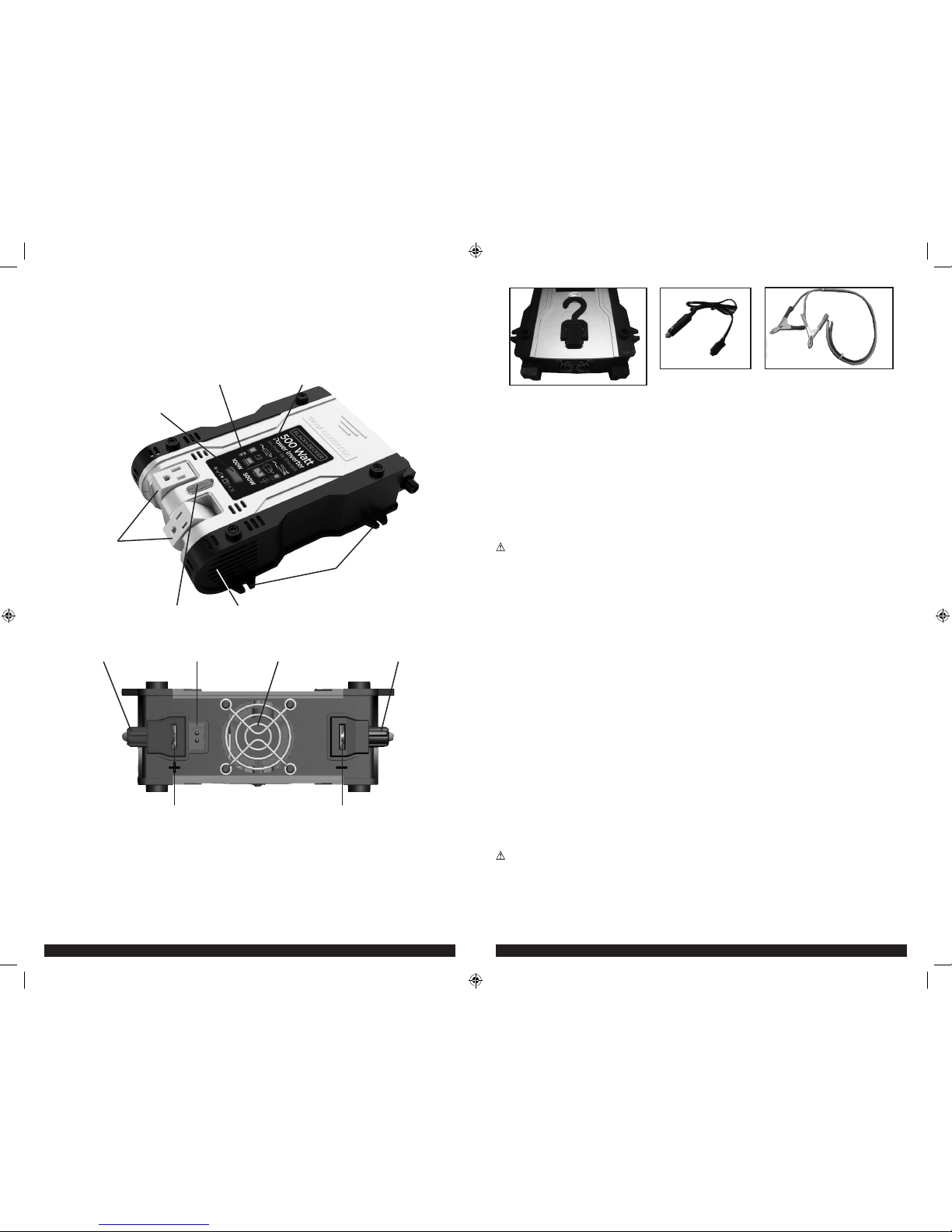
Conexión a la fuente de energía
El Inversor eléctrico viene equipado con un enchufe de salida para accesorios de CD y cables para pinzas de la
batería para su conexión a una fuente de energía.
CONEXIÓN A UNA FUENTE DE ENERGÍA MEDIANTE EL TOMACORRIENTE PARA ACCESORIOS DE CC
(HASTA 100 W ÚNICAMENTE)
El tomacorriente para accesorios de CC es apto para operar el inversor con salidas de energía de hasta 100
vatios y posee una protección contra la sobrecarga de 100 vatios para evitar que se queme el fusible si conecta
un artefacto con una capacidad nominal más alta. La punta del enchufe es positiva (+) y el contacto lateral es
negativa (–).
El extremo opuesto del tomacorriente para accesorios de CC cuenta con un conector único instalado que
permite insertarlo únicamente en el receptáculo de la parte trasera de la unidad cuando las pinzas para batería
NO están conectadas a la unidad. Esta es una característica de seguridad y el diseño del enchufe cubre también
el terminal positivo (+) para evitar que ambos
conductores se conecten al mismo tiempo.
• Conecte el inversor a la fuente de energía insertando el enchufe de salida para accesorios de CC con firmeza
dentro del tomacorriente para accesorios de un vehículo o de otra fuente de energía. Cerciórese de que haya
espacio adecuado para la ventilación apropiada del inversor.
• Presione el botón translúcido de encendido / apagado.
• Se iluminará el indicador de LED 100 vatios, que indica que el inversor esté funcionando correctamente y está
listo para alimentar artefactos que consumen hasta 100 vatios continuos.
Notas:
Si el indicador LED de encendido / falla parpadea en rojo, la unidad emite tres sonidos cada cinco segundos, el indicador LED de 100
vatios no se enciende y las tomas de CA y USB cerradas, se ha producido una condición de error. Consulte la sección “Solución de
problemas” de este manual.
Si el inversor no funciona cuando se utiliza la salida de accesorios del vehículo, asegúrese de que el interruptor de encendido/
accesorio realmente está impulsando el tomacorriente para accesorios. Algunos vehículos requieren el interruptor de encendido esté
activada
La mayoría de los circuitos de salida para accesorios del vehículo poseen fusibles clasificados en 15 a 20 amperios o más. Para
operar a la potencia en vatios máxima, utilice el cable de la pinza de la batería (suministrado) o conecte directamente a la fuente
de energía con el cable y el fusible suministrado por el usuario. La mayoría de los automóviles modernos, vehículos recreativos y
camiones posee un negativo a tierra.
PRECAUCIONES
• Conecte directamente a una fuente de energía al operar a más de 100 vatios.
• No utilice con sistemas eléctricos con positivo a tierra.
• La conexión de polaridad inversa hará que un fusible se queme y puede causar un daño permanente al
inversor
CONEXIÓN A UNA FUENTE DE ALIMENTACIÓN MEDIANTE LAS PINZAS DE BATERÍA SUMINISTRADO CON
LOS CONECTORES DESLICE
Utilice las pinzas de la batería (con cables y conectores deslice) para conectar el inversor de corriente
directamente a la fuente de alimentación de 12 voltios como sigue:
1. Revise para asegurarse del potencia y fallas LED no se enciende y que no haya vapores inflamables están
presentes en el área de instalación.
2. Gire la tapa de plástico roja (sentido antihoraria) en positivo (+) del conversor cable post y quitar. Fije la
conectore positiva al final del cable clip rojo de la batería en la ranura del positivo (+) entrada de cable.
Vuelva a colocar la tapa y gire hacia la derecha para asegurar. No apriete en exceso.
3. Conecte la pinza de batería roja al terminal positivo de la batería.
4. Abra la tapa de plástico negra (sentido antihorario) negativo del inversor (–) cable y quitar. Fije la conectore
negativa al final del cable clip negro en la ranura del poste de cable negativo (–). Vuelva a colocar la tapa y
gire hacia la derecha para asegurar. No apriete en exceso.
5. Conecte la una pinza de batería negro al terminal negativo de la batería.
6. Asegúrese de que todas las conexiones entre los cables y terminales estén seguras.
7. Presione el botón translúcido de encendido / apagado.
8. Los indicadores LED 100 vatios y 500 vatios se encenderá, indicando que el inversor esté funcionando
correctamente y está listo para alimentar artefactos que consumen hasta 500 vatios continuos.
Nota:
Si el indicador LED de encendido / falla parpadea en rojo, la unidad emite tres sonidos cada cinco segundos, los indicadores LED
de 100W y 500W no se enciende y las tomas de CA y USB cerradas, se ha producido una condición de error. Consulte la sección
“Solución de problemas” de este manual.
CABLEADO DIRECTO A LA FUENTE DE ENERGÍA (MÉTODO OPCIONAL DE CONEXIÓN; CABLES NO
INCLUIDOS)
ADVERTENCIA:
Para evitar que el inversor funcione en forma defectuosa, se recomienda no instalarlo con
cables de una extensión superior a 3 m (10 pies).
Utilice el alambre del AWG #10 si el inversor a la conexión de la fuente de energía es 10 pies o menos. Para
longitudes de cable más largas utilice el alambre del AWG #8. En cualquier caso, proteja (+) el alambre positivo
contra cortocircuitos instalando un fusible o un interruptor de 50A cerca del terminal de la fuente de la potencia
CC (batería).
1.Asegúrese de que el indicador de poder/fallas dentro del interruptor transluciente no esté encendido y que no
haya presencia de vapores inflamables en el área de instalación.
2. Identifique los terminales positivo (+) y negativo (–) (batería) de la fuente de energía de cd.
3. Instale un soporte para fusibles o interruptor cerca del terminal positivo (+) de la fuente de
energía (batería) de cd.
4. Conecte una extensión de cable en un lado del soporte del fusible o del interruptor automático. Conecte el
otro extremo del cable al terminal positivo (+) del inversor.
5. Conecte una extensión de cable entre el terminal negativo (–) del inversor y el terminal negativo (–) de la
fuente de energía de CC.
6. Conecte una extensión corta de cable al otro terminal del soporte del fusible o al interruptor
automático. Márquelo como “positivo” o “+”.
7. Conecte el extremo libre del fusible o del cable del interruptor al terminal positivo (+) de la fuente de energía
(batería) de CC.
8. Inserte un fusible adecuado al inversor en el soporte del fusible.
9. Presione el botón translúcido de encendido / apagado.
10. Los indicadores LED 100 vatios y 500 vatios se encenderá, indicando que el inversor esté funcionando
correctamente y está listo para alimentar artefactos que consumen hasta 500 vatios continuos.
11. Pruebe el inversor encendiéndolo y enchufándolo en una lámpara o equipo de 100 vatios.
Nota:
Si el indicador LED de encendido / falla parpadea en rojo, la unidad emite tres sonidos cada cinco segundos, los indicadores LED
de 100W y 500W no se enciende y las tomas de CA y USB cerradas, se ha producido una condición de error. Consulte la sección
“Solución de problemas” de este manual.
PRECAUCIONES
• En general, se recomienda utilizar un cable y un fusible del tamaño indicado. Consulte siempre el Código de
Electricidad Nacional correspondiente antes de empezar cada
instalación.
• Los conectores sueltos pueden hacer que los cables se sobrecalienten y que el aislamiento se derrita.
• Compruebe para asegurarse de que no ha invertido la polaridad. Los daños ocasionados por
polaridad inversa no están cubiertos por nuestra garantía.
INFORMACIÓN IMPORTANTE SOBRE LOS CABLES
La pérdida considerable de potencia y el menor tiempo de operación de la batería se debe a inversores
instalados con cables que no pueden suministrar una potencia plena. Los síntomas de potencia baja de la
batería pueden deberse a que los cables son excesivamente largos o a un calibre insuficiente.
PI500P_ManualENSP_073015.indd 18-19 7/30/2015 5:44:22 PM