Body Break 1611325 User manual

Owner’s Manual
Model No.
1611325
- Assembly
- Operation
- Adjustments
- Parts
- Warranty
CAUTION:
Read and
Understand this
Manual before
Operating unit
Retain For
Future Reference

Customer Service 1-888-707-1880 Dyaco Canada Inc. 2013
TABLE OF CONTENTS
Important Safety Instructions………………………………………………….2
Important Electrical Instructions………………………………………………4
Assembly instructions…………………………………………………………. 5
Folding/ Transport Instructions………………………………………………..11
Operation of Your New Treadmill……………………………………….……12
Exploded View Diagram/Parts List………………………………………...…17
General Maintenance……………………………………..……………………21
Manufacturer’s Limited Warranty………………………………………....…..24

Customer Service 1-888-707-1880 Dyaco Canada Inc. 2013
IMPORTANT SAFETY INFORMATION
THIS UNIT IS INTENDED FOR HOUSEHOLD USE ONLY
READ ALL INSTRUCTIONS BEFORE USING THIS TREADMILL
▲CAUTION: Before starting any exercise program, it is recommended that you consult your
physician.
▲WARNING: Connect this unit to a properly grounded outlet only.
▲DANGER: To reduce the risk of electric shock, always unplug the treadmill from the electrical outlet
immediately after using and before cleaning.
WARNING
To reduce the risk of burns, fire, electric shock, or injury to persons:
1. Use 120 volt a.c. household current on a dedicated circuit.
Grounding Instructions
This product must be grounded. If it should malfunction or breakdown, grounding provides a path of least
resistance for electric current to reduce the risk of electric shock. This product is equipped with a cord having an
equipment-grounding conductor and a grounding plug. The plug must be plugged into an appropriate outlet that is
properly installed and grounded in accordance with all local codes and ordinances. See diagram below for
grounding methods.
2. It is the responsibility of the owner to ensure that all users of this treadmill are adequately informed of
all warnings and precautions.
3. The use of an extension cord with this product is not recommended. If an extension cord is needed,
use a short (less than 10 feet) heavy gauge (14 gauge or better) extension cord with a three prong
(grounded) plug and receptacle.
4. Never leave the treadmill unattended when plugged in. Remove the safety key and unplug the unit
from the outlet when not in use and before removing or replacing parts.
5. Never operate the treadmill if it has a damaged cord or plug, if it is not working properly, if it has been
dropped, damaged, or exposed to water. Never move the treadmill belt while the power is turned off.
6. Do not pull the treadmill by the power supply cord or use cord as a handle. Keep cord away from
heated surfaces and open flames.
7. Fitness equipment must always be installed and used on a flat surface. Do not use outdoors or near
water. Do not place the unit on a loose rug or uneven surface. It is recommended to use an equipment
mat to prevent the unit from moving while it is being used, which could possibly scratch or damage the
surface of your floor. It is recommended to have a minimum of 3 metres safe clearance on all sides of
the treadmill while in use.
8. Keep the treadmill indoors, away from moisture and dust. Do not put the treadmill in a garage, covered
patio or near water.
9. Do not operate the treadmill where aerosol products are used or where oxygen is being administered.
10. Read, understand, and test the emergency stop procedure before using the treadmill. Do not insert
any objects into any openings.
11. Inspect and properly tighten all parts of the treadmill regularly.
12. Keep children and pets away from this equipment at all times while exercising.

Customer Service 1-888-707-1880 Dyaco Canada Inc. 2013
13. Handicapped individuals should have medical approval and close supervision when using this
treadmill.
14. Do not place hands or feet under the treadmill. Always keep hands and legs off of the treadmill when
others are using it.
15. Never turn on treadmill while standing on treadbelt. Always hold the handrails while using the treadmill.
Always return the treadmill to the slowest speed to provide for safe dismount and low speed restart.
16. To disconnect, turn all controls to the off position, then remove plug from outlet.
17. Do not attempt to raise, lower or move the treadmill until it is properly assembled. See assembly on
page 5and to fold and move the treadmill on page 11. Care must be taken when lifting or moving the
equipment, so as not to injure your back. Always use proper lifting techniques. You must use any
attachments that are not recommended by the manufacturer.
18. Use the treadmill only for its intended use as described in this manual. Do not use any attachments
that are not recommended by the manufacturer.
19. User weight should not exceed 350lbs (159 kg).
20. Never allow more than one person on the treadmill at once.
21. Warm up 5 to 10 minutes before each workout and cool down 5 to 10 minutes afterward. This allows
your heart rate to gradually increase and decrease and will help prevent straining muscles.
22. Never hold your breath while exercising. Breathing should remain at a normal rate in conjunction with
the level of exercise being performed.
23. Start your program slowly and very gradually increase your speed and distance.
24. Always wear suitable clothing and footwear while exercising. Do not wear loose fitting clothing that
could become entangled with the moving parts of your treadmill. Do not walk or jog barefoot, in
stocking feet or loose fitting shoes or slippers.
25. This treadmill is intended for in-home use only. Do not use the treadmill in any commercial, rental or
institutional setting.
▲WARNING: Before beginning any exercise program consult your physician. This is especially important for
individuals over the age of 35 or persons with preexisting health problems. Read all instructions before using
any fitness equipment. We assume no responsibility from personal injury or property damage sustained by or
through the use of this product.
SAVE THESE INSTRUCTIONS

Customer Service 1-888-707-1880 Dyaco Canada Inc. 2013
WARNING!
●NEVER use a ground fault circuit interrupt (GFCI) wall outlet with this treadmill. Route the power cord away
from any moving part of the treadmill including the elevation mechanism and transport wheels.
●NEVER remove any cover without first disconnecting AC power.
●If voltage varies by ten percent (10%) or more, the performance of your treadmill may be affected. Such
conditions are not covered under your warranty. If you suspect the voltage is low, contact your local power
company or a licensed electrician for proper testing. See Diagnosis Guide, page 23.
●NEVER expose this treadmill to rain or moisture. This product is NOT designed for use outdoors, near a pool or
spa, or in any other high humidity environment.
This product must be grounded. If the treadmill should malfunction or breakdown, grounding provides a path
of least resistance for electric current, reducing the risk of electric shock. This product is equipped with a cord
having an equipment-grounding plug. The plug must be plugged into an appropriate outlet that is properly
installed and grounded in accordance with all local codes and ordinances.
DANGER - Improper connection of the equipment-grounding conductor can result in a risk of electric
shock. Check with a qualified electrician or serviceman if you are in doubt as to whether the product is
properly grounded. Do not modify the plug provided with the product if it will not fit the outlet; have a
proper outlet installed by a qualified electrician.
●NEVER operate this treadmill without reading and completely understanding the results of any operational
change you request from the computer.
●Understand that changes in speed and incline do not occur immediately. Set your desired work level on the
computer console and release the adjustment key. The computer will obey the command gradually.
●NEVER use your treadmill during an electrical storm. Surges may occur in your household power supply that
could damage treadmill components.
●Use caution while participating in other activities while walking on your treadmill, such as watching television,
reading, etc. These distractions may cause you to lose balance or stray from walking in the center of the belt;
which may result in serious injury.
●NEVER mount or dismount the treadmill while the belt is moving. Our treadmills start with at a very low speed
and it is unnecessary to straddle the belt during start up. Simply standing on the belt during slow acceleration is
proper after you have learned to operate the unit.
●Always hold on to a handrail or hand bar while making control changes (incline, speed, etc.).
Do not use excessive pressure on console control keys. They are precision set to function properly with little
finger pressure. Pushing harder is not going to make the unit go faster or slower. If you feel the buttons are not
functioning properly with normal pressure, contact your dealer.
Important Electrical Information

Customer Service 1-888-707-1880 Dyaco Canada Inc. 2013
!!ATTENTION: IMPORTANT UNPACKING INSTRUCTIONS.
PLEASE READ BEFORE UNPACKING YOUR FOLDING TREADMILL!!
Serious injury could occur if this folding treadmill is not unpacked properly.
There is a Velcro strap installed around the treadmill base that prevents the treadmill from
unfolding accidentally during shipping. If this strap is not removed properly the treadmill could
spring open unexpectedly and cause injury if someone is standing near the treadmill when the
strap is removed.
To ensure your personal safety during removal of the shipping strap please make sure the
treadmill is positioned flat on the ground, in the orientation it would be in if you were using the
treadmill. Do not turn the treadmill up on its side while removing the shipping strap. This could
cause the treadmill’s folding mechanism to spring open. If the end of the Velcro strap (that you
need to grab to remove it) happens to be under the treadmill deck, reach under the deck to
grab it, but do not tilt the treadmill up to gain access to the strap end.
Unpack the treadmill and locate the hardware pack. The hardware pack is separated into five
sections; one section containing tools and four sections labeled steps 1-4 which contain the
hardware needed for assembly of each step. The assembly steps below are numbered one
through four and correspond to the hardware in the numbered sections of the hardware pack.
Remove only the hardware for the step you are currently assembling to avoid confusion and
mix ups.
Assembly Instructions
Customer Service 1-888-707-1880 Dyaco Canada Inc. 2013
Email: customerservice@dyaco.ca 6
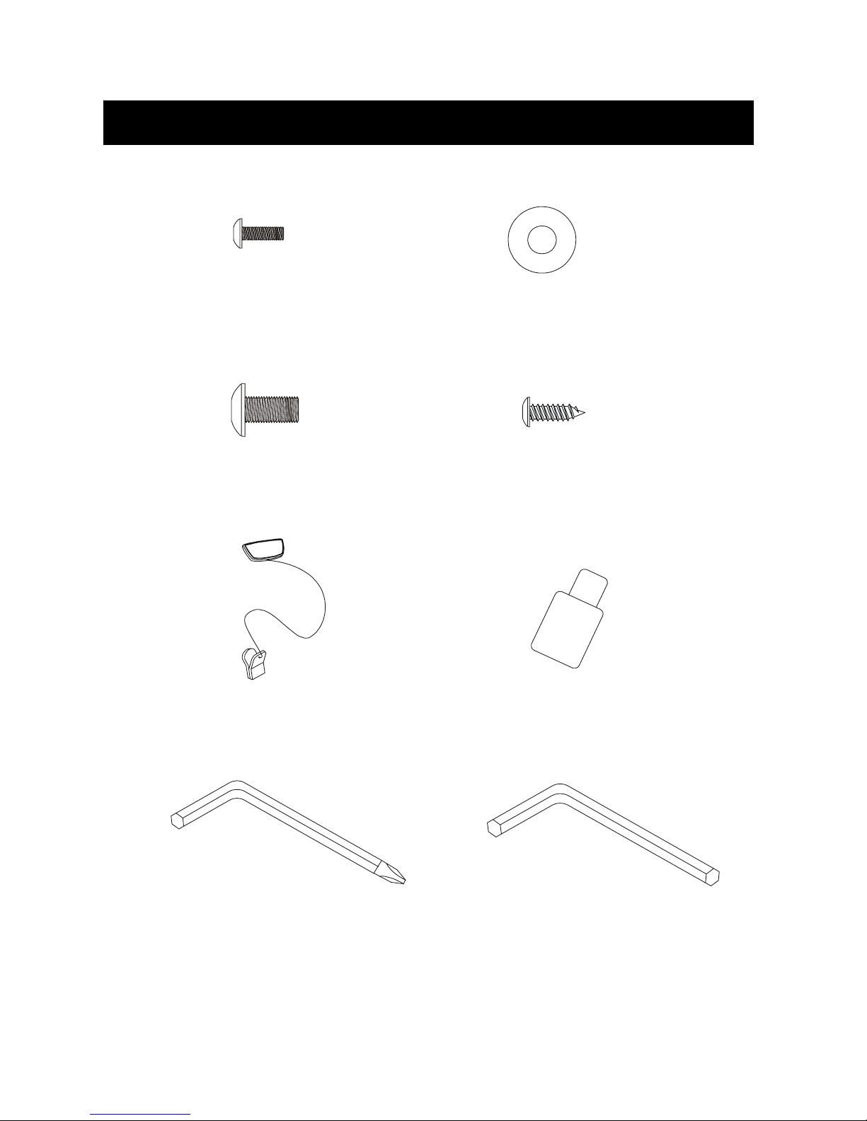
Assembly Instructions
#96. M5×10m/m
Phillips Head Screw (6pcs) #95. Ø8×Ø19×1.5T
Curved Washer (8pcs)
#94. 5/16" × 15m/m
Button Head Socket Bolt
(14pcs)
#90.Ø3.5 × 12m/m
Sheet Metal Screw (4pcs)
#102. Safety Key (1pc) #93. Lubricant (1pc)
#98. M6 (66 × 86)
L Allen Wrench (1pc)
#97. Combination M5 Allen Wrench &
Phillips Head Screw Driver (1pc)
Customer Service 1-888-707-1880 Dyaco Canada Inc. 2013
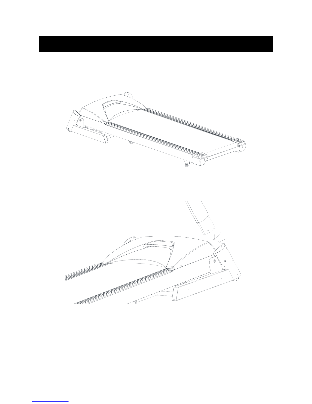
Step 1.
Remove the treadmill from the carton and lay it on a smooth level surface.
Step2.
Connect the Lower Computer Cable(38) to the Extension Computer Cable(37).
37
38
Assembly Instructions
Customer Service 1-888-707-1880 Dyaco Canada Inc. 2013
Step 3
Insert the Left Upright(4 into the Frame Base (2). Secure using four 5/16"x15mm Button
Head Socket Bolts (94) and four Ø8 x 19 x 1.5T Curved Washers (95) using the
Combination M5 Allen Wrench & Phillips Head Screw Driver (97).
Repeat for the Right Upright (5).
94
95
94
94
94
95
5
4
97
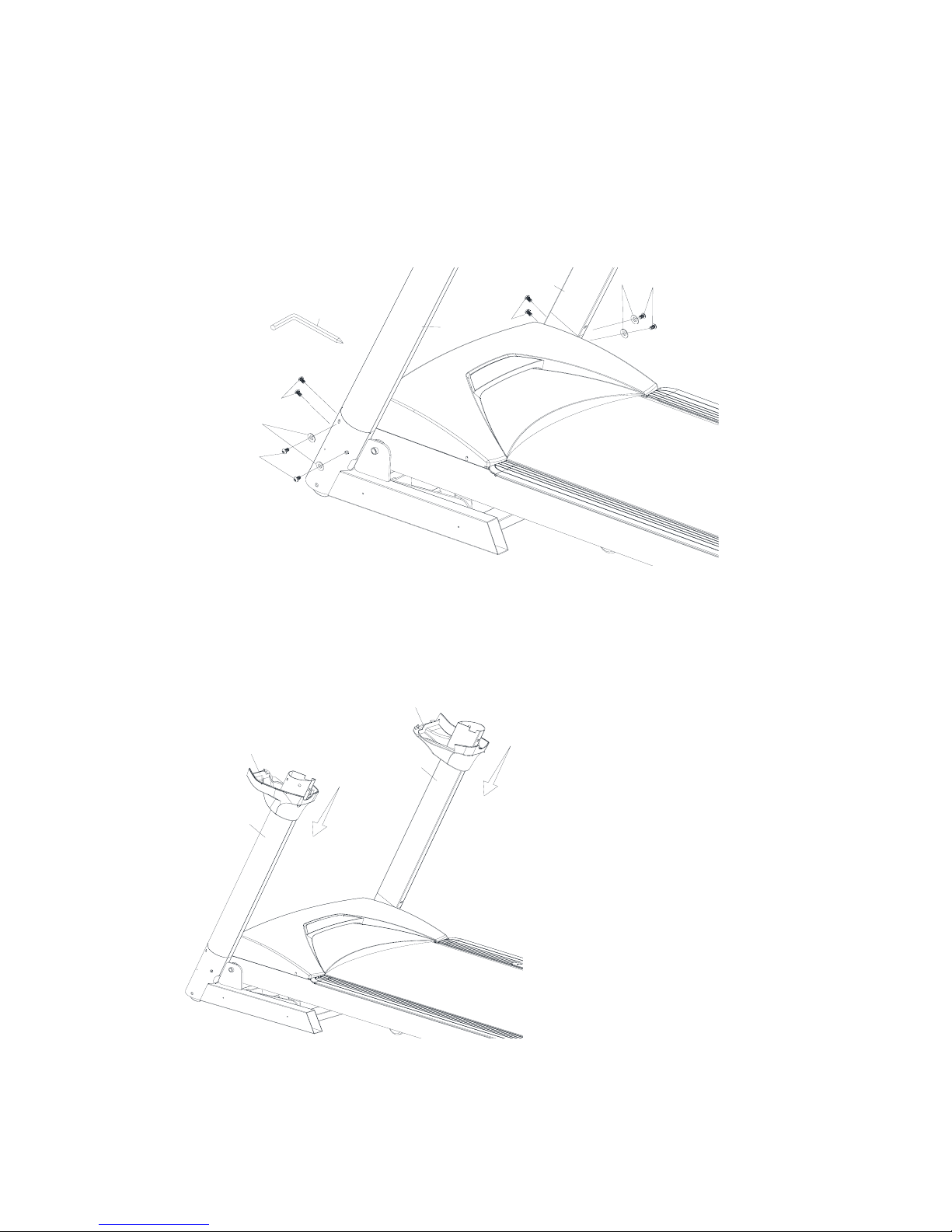
Step 4.
Install the Left Handrail Base Cover (41) through the Left Upright (4). Install the Right
Handrail Base Cover(40) through the Right Upright (5).
41
4
5
40

Customer Service 1-888-707-1880 Dyaco Canada Inc. 2013
Step 5.
Connect the Extension Computer Cable(37) to the Upper Computer Cable (36).
36
37
Step 6.
Install the Console Assembly (39) into the Right and Left Uprights (4,5). Secure using six
5/16"x15mm Button Head Socket Bolts (94) and four Ø8 x 19 x 1.5T Curved Washers (95)
using the Combination M5 Allen Wrench & Phillips Head Screw Driver (97).
95
94
94
94 94
94 94
95 95
97
5
4
39

Customer Service 1-888-707-1880 Dyaco Canada Inc. 2013
Step 7.
Secure the Left and Right Handrail Base Covers (41, 40) to the Console Assembly (39)
using four 3.5x12mm Sheet Metal Screws (90) by using the Combination M5 Allen Wrench
& Phillips Head Screw Driver (97).
90 90
40
41
39
97
Step 8.
Install the Left Frame Base Cover (44) onto the Frame Base (2). Secure using six
M5x10mm Phillips Head Screws (96) by using the Combination M5 Allen Wrench &
Phillips Head Screw Driver (97).
Repeat for the right side.
9744
43
96
96 96
96
96 96
2
NOTE: Ensure that you Tighten All Screws After your assembly is complete.

Customer Service 1-888-707-1880 Dyaco Canada Inc. 2013
Do not attempt to move the unit unless it is in the folded and locked into position. Be sure the power cord is
secured to avoid possible damage. Use both handrails to maneuver the unit to the desired position.
■Unfoldong The Treadmill:
Apply slight forward pressure* on the treadmill running deck with one hand. Pull down on the unlocking lever and
slowly lower the running deck to the floor. The deck will lower unassisted when it reaches about waist high. (As
shown Figure 1&2.)
*At the rear roller area to relieve pressure on the locking system.
■Folding The Treadmill:
Make certain the treadmill is at minimum incline. Lift the treadmill running deck until it is secured by the locking
telescoping tube assembly in center back of base.(As shown Figure 3.)
■Transport
The treadmill is equipped with four transport wheels which are engaged when the treadmill is folded. After folding
simply roll the treadmill away. (As shown Figure 4.)
The treadmill is equipped with four transport wheels that are engaged when the treadmill is folded. After folding
simply roll the treadmill away.
Folding Instructions
Transportation
Customer Service 1-888-707-1880 Dyaco Canada Inc. 2013
Initial Display:
When the power is turned on, the main display will light up showing all characters. The console will
be performing an internal test to make sure the console is operational. The display will then scroll
through three numbers, the first showing the current software version, second is how many hours
the treadmill has been in use and third is how many virtual miles the treadmill has gone. The
treadmill will then enter idle mode and show P0 MANUAL on the display, which is the starting point
for operation.
Operation of Your New Treadmill

Customer Service 1-888-707-1880 Dyaco Canada Inc. 2013
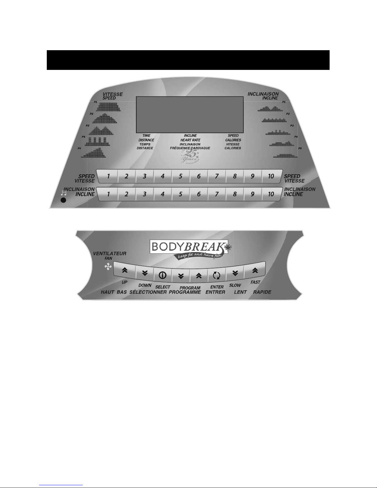
WINDOW DISPLAY DATA:
SPEED: Displays the current belt speed from starting at 0.8 mph to 12.0 mph.
TIME: Accumulates total workout time from 00:00 to 99:59.
DISTANCE: Accumulates total workout distance from 0.00 to 99.99 miles.
CALORIES: Accumulates the user’s calorie consumption during exercise. Max. Value is 9999
calories.
PULSE: Displays your current heart rate in beats per minute from 40 to 240.
♥Icon: The heart icon blinks when a pulse is detected.
INCLINE: When lit, the display showing the elevation position from 0 to 12.
FUNCTION BUTTONS:
START: Press “START” button to start training.
STOP: Press “STOP” button to stop training and press for 3 seconds to reset.
FAST: Press “FAST’ button to increase your speed.
SLOW: Press “SLOW” button to decrease your speed.
UP: Press “UP” button to increase elevation position.
DOWN: Press “DOWN” button to decrease elevation position.
ENTER: Press “ENTER” button to select different setting parameters in STOP mode.
SELECT: Press “SELECT” button to scroll through the display workout information.
PROGRAM UP/DOWN: Press PROGRAMUP/DOWN buttons to scroll through workout programs.
RAPID SPEED KEYS: 10 preset speed buttons to jump to a desired speed quickly. You can also
press the any of the 10 buttons to start treadmill from the start-up screen.
The treadmill will automatically start and slowly increase speed to the preset
number.
RAPID INCLINE KEYS: 10 preset incline buttons to jump to a desired incline setting quickly.
Quick-Start Operation:
STEP 1: Attach the Safety key to wake display up (if not already on). The main window will show
the initial display: P0.
STEP 2: Press the START button to begin belt movement after a three second count down. Use the
FAST/SLOW keys to adjust the desired speed at any time during training. Using the
UP/DOWN keys to adjust the Incline at any time during training.
STEP 3: Press the ENTER button to exchange display speed, incline, time, calories, distance and
pulse.
STEP 4: To get a pulse reading, simply grasp both stainless steel pick-ups. Make sure the display
is set to show Pulse, or Scan. When the ♥Icon is flashing that means the console is
receiving a pulse. It may take a few seconds for the display to reach the actual number.
STEP 5: While training, you can press STOP button to stop your workout or pull safety key away
from its position to shut down the computer. If you want to resume your workout, you can
press START button and all previous data will resume counting.

Customer Service 1-888-707-1880 Dyaco Canada Inc. 2013
PROGRAMS
MANUAL(P0)
STEP 1: Press Program UP/DOWN button to highlight Manual (P0) and press enter.
STEP 2: You can set count down time from 10:00 to 99:00. Press FAST/SLOW to adjust the value
and then press the ENTER button to continue to the next step. If you leave the value at
00:00, the time will count up.
STEP 3: You can set the DISTANCE to count down also. If the distance and time are both set to
count down, the first one to reach zero will end the program. Press FAST/SLOW buttons to
adjust, then press ENTER. If you do not set the distance to count down the console will
count up from zero.
STEP 4: Press FAST/SLOW buttons to adjust the weight, then press enter.
STEP 5: Press START to begin the program.
STEP 6: During the program you can adjust the speed and incline by pressing “FAST/SLOW and
“UP/DOWN” buttons, or use rapid keys to jump directly to a setting.
STEP 7: Press “STOP” button to stop your workout or pull safety key away from its position to shut
down the computer. The Stop button will Pause the program the first time it is pressed. The
second time will end the program.
PRESET PROGRAM (P1~P5)
STEP 1: Press Program UP/DOWN buttons to scroll through the pre-set programs. Press Enter to
select the program you desire.
STEP 2: The first parameter is Speed. This is the maximum speed for the program. The program will
change speeds during your workout and setting the top speed makes sure the program
won’t go too fast, or too slow for your purposes. Use the FAST/SLOW (UP/DOWN) keys to
adjust.
STEP 3: The pre-set value of time is 20:00, and the range is from 00:00 to 99:00. Press
FAST/SLOW (UP/DOWN) keys to modify, and press ENTER to accept and continue to the
next step.
STEP 4: Press FAST/SLOW (UP/DOWN) keys to adjust the weight and press enter.
STEP 5: Press START button to begin your workout.
STEP 6: During the program you can adjust the SPEED and INCLINE by pressing “FAST/SLOW
button and “UP/DOWN” button, or use rapid keys to jump directly to a setting.
STEP 7: Press “STOP” button to stop your workout or pull safety key away from its position to
shut down the computer.

Customer Service 1-888-707-1880 Dyaco Canada Inc. 2013
USER (U1~U2)
STEP 1: Press PROGRAM UP/DOWN buttons to select the program you desire.
STEP 2: The pre-set value of time is 20:00, and the range is from 00:00 to 99:00. Press FAST/SLOW
(UP/DOWN) buttons to modify and then press ENTER to continue.
STEP 3: Press FAST/SLOW (UP/DOWN) buttons to adjust the weight, then press enter.
STEP 4: Using the Fast / Slow keys, adjust the speed level to your desired effort for the first
segment, then press Enter. The second column will now be blinking. Repeat the above
process until all segments have been programmed. The first column will be blinking again.
This is for the incline programming. Repeat the above process to program all segments for
incline.
STEP 5: Press the Start button to begin the workout and also save the program to memory.
STEP 6: During the program you can press “FAST/SLOW” button to adjust SPEED, and press
“UP/DOWN” button to adjust incline; or use rapid keys to jump to a preset level.
STEP 7: Press “STOP” button to stop your workout or pull safety key away from its position to shut
down the computer.
TARGET HRC (H1~H2)
STEP 1: Press PROGRAM UP/DOWN buttons to select the HRC mode that you want and press
enter.
STEP 2: The pre-set value of time is 20:00, and the range is from 00:00 to 99:00. Press
FAST/SLOW (UP/DOWN) buttons to modify and press ENTER to continue to the next step.
STEP 3: Press FAST/SLOW (UP/DOWN) button to adjust the weight and press enter.
STEP 4: Press FAST/SLOW (UP/DOWN) buttons to adjust the age and press enter.
STEP 5: Press FAST/SLOW (UP/DOWN) to adjust target Heart Rate, then press ENTER button to
proceed to the next step.
STEP 6: Press FAST/SLOW (UP/DOWN) button to modify the maximum speed. The range is from
0.8 to 12.0mile. Press ENTER button to enter next step.
STEP 7: Press FAST/SLOW (UP/DOWN) buttons to adjust max grade. The range is from 0 to 12.
Finally press ENTER button to finish.
STEP 8: Press START to execute your program, or press START button to start training directly,
STEP 9: Press “STOP” button to stop your workout or pull safety key away from its position to shut
down the computer.
Optional: There is an Audio Input Jack on the front of the console and built-in speakers. You may
plug any low-level audio source signal into this port. Audio sources include MP3, Ipod,
portable radio, CD player or even a TV or computer audio signal. There is an audio patch
cable included to and also a headphone jack for private listening.
Customer Service 1-888-707-1880 Dyaco Canada Inc. 2013
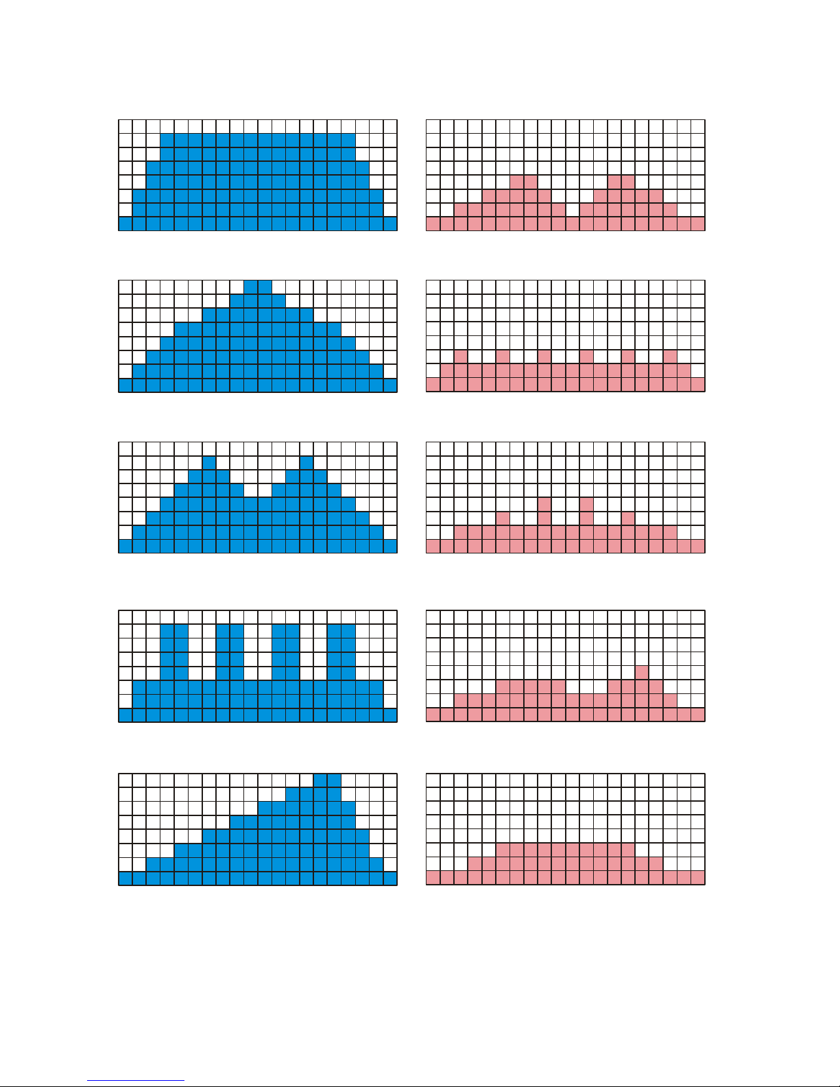
SPEED PROFILE
P.1
INCLINE PROFILE
P.1
P.2
P.2
P.3
P.3
P.4 P.4
P.5
P.5

Customer Service 1-888-707-1880 Dyaco Canada Inc. 2013
KEY NO. PART NO. DESCRIPTION Q'TY
1 132501 Main Frame 1
2 132502 Frame Base 1
3 132503 Incline Bracket 1
4 132504 Left Upright 1
5 132505 Right Upright 1
6 132506 Console Support 1
7 132507 Outer Slide 1
8 132508 Inner Slide 1
9 132509 Locking Knob 1
10 132510 Frame Cover 1
11 132511 Belt Guide 2
12 132512 Running Deck 1
13 132513 Running Belt 1
14 132514 Drive Belt 1
15 132515 Front Roller W/Pulley 1
16 132516 Rear Roller 1
17 132517 Wheel Sleeve 2
18 132518 Magnet 2
19 132519 Cylinder 1
20 132520 Handgrip Foam 2
21 132521 Wire Tie Mount 5
22 132522 Drive Motor 1
23 132523 Incline Motor 1
24 132524 Motor Controller 1
25 132525 Speed Adjustment Switch W/Cable 1
26 132526 Incline Adjustment Switch W/Cable 1
27 132527 Handpulse Sensor (w/o wire) 2
27~1 132527~1 750m/m_Handpulse Wire 1
27~3 132527~3 Handpulse Top Cover 2
27~4 132527~4 Handpulse Bottom Cover 2
28 132528 Breaker 1
29 132529 Power Socket 1
30 132530 On/Off Switch 1
31 132531 Sensor W/Cable 1
32 132532 Power Cord 1
33 132533 200m/m_Connecting Wire (White) 1
34 132534 200m/m_Connecting Wire (Black) 1
35 132535 100m/m_Connecting Wire (Black) 1
36 132536 800m/m_12P Upper Computer Cable 1
37 132537 1100m/m_12P Extension Computer Cable 1
38 132538 1100m/m_12P Lower Computer Cable 1
39 132539 Console Assembly 1
39~1 132539~1 Console Top Cover 1
Parts List and Diagram

Customer Service 1-888-707-1880 Dyaco Canada Inc. 2013
KEY NO. PART NO. DESCRIPTION Q'TY
39~2 132539~2 Console Bottom Cover 1
39~3 132539~3 Front Console Cover (Inner) 1
39~4 132539~4 Console Speaker Cover (R) 1
39~5 132539~5 Console Speaker Cover (L) 1
39~6 132539~6 START Key (L) 1
39~7 132539~7 STOP Key (R) 1
39~8 132539~8 Speaker Grill Anchor 6
39~13 132539~13 Amplifier Controller 1
39~14 132539~14 600m/m_Amplifier Cable 1
39~15 132539~15 300m/m_Speaker W/Cable 1
39~16 132539~16 750m/m_Speaker W/Cable 1
39~17 132539~17 Sound Board W/Cable (Red) 1
39~19 132539~19 Safety Switch Module W/ Cable 1
39~20 132539~20 Square Magnet Stop Plate 2
39~21 132539~21 Fan Assembly 2
39~22 132539~22 Deflector Fan Grill 2
39~23 132539~23 Fan Grill Anchor 4
39~24 132539~24 Ø3.5 × 32m/m_Sheet Metal Screw 8
39~30 132539~30 Ø3 × 10m/m_Sheet Metal Screw 14
39~31 132539~31 W/Receiver, HR 1
40 132540 Handrail Base Cover(R) 1
41 132541 Handrail Base Cover(L) 1
42 132542 Button Head Plug 2
43 132543 Frame Base Cover (R) 1
44 132544 Frame Base Cover (L) 1
45 132545 Transportation Wheel 2
46 132546 Transportation Wheel(B) 2
47 132547 Motor Cover Anchor(C) 2
48 132548 Motor Top Cover 1
49 132549 Top Motor Cover Plate 1
50 132550 Front Motor Cover 1
53 132553 Aluminum Foot Rail 2
55 132555 Rear Adjustment Base (L) 1
56 132556 Rear Adjustment Base (R) 1
57 132557 Adjustment Foot Pad Cap 2
58 132558 Cushion 6
59 132559 Adjustment Foot Pad 2
60 132560 Sensor Rack 1
61 132561 Ø24 × Ø10 × 3T_Nylon Washer (A) 3
62 132562 Ø50 × Ø13 × 3T_Nylon Washer (B) 4
63 132563 1/2" × 1-1/4"_Carriage Bolt 2
64 132564 1/2" × 1"_Hex Head Bolt 2
65 132565 3/8" × 4"_Hex Head Bolt 1
66 132566 3/8" × 92m/m_Hex Head Bolt 1
67 132567 3/8" × 1"_Hex Head Bolt 4
68 132568 3/8" × 1-1/2"_Hex Head Bolt 1
69 132569 3/8" × 45m/m_Hex Head Bolt 1
70 132570 3/8" × 60m/m_Flat Head Socket Bolt 2
71 132571 5/16" × 1"_Button Head Socket Bolt 4

Customer Service 1-888-707-1880 Dyaco Canada Inc. 2013
KEY NO. PART NO. DESCRIPTION Q'TY
72 132572 M8 × 60m/m_Hex Head Bolt 1
73 132573 M8 × 65m/m_Socket Head Cap Bolt 2
74 132574 M8 × 25m/m_Flat Head Countersink Bolt 8
75 132575 1/2" × 8.0T_Nyloc Nut 4
76 132576 3/8" × 7.0T_Nyloc Nut 6
77 132577 5/16" × 6T_Nyloc Nut 2
78 132578 M8 × 7.0T_Nyloc Nut 1
79 132579 3/8" × 7.0T_Nut 3
80 132580 Ø8 × Ø35 × 1.5T_Flat Washer 2
81 132581 Ø10 × Ø25 × 2.0T_Flat Washer 4
82 132582 Ø10 × Ø19 × 1.5T_Flat Washer 6
83 132583 Ø10 × 2.0T_Split Washer 4
84 132584 Ø5 × Ø16 × 1.0T_Flat Washer 4
85 132585 Ø5 × 1.5T_Star Washer 3
86 132586 Ø4 × 12m/m_Sheet Metal Screw 4
87 132587 Ø5 × 16m/m_Tapping Screw 32
88 132588 Ø5 × 19m/m_Tapping Screw 5
89 132589 Ø5 × 16m/m_Tapping Screw 8
90 132590 Ø3.5 × 12m/m_Sheet Metal Screw 13
91 132591 Ø4 × 38m/m_Sheet Metal Screw 2
92 132592 Ø3.5 × 16m/m_Tapping Screw 5
93 132593 Lubricant 1
94 132594 5/16" × 15m/m_Button Head Socket Bolt 14
95 132595 Ø8 × Ø19 × 1.5T_Curved Washer 8
96 132596 M5 × 10m/m_Phillips Head Screw 6
97 132597 Combination M5 Allen Wrench & Phillips Head Screw Driver 1
98 132598 M6 ( 66 × 86 )_L Allen Wrench 1
99 132599 3/8" × 2"_Hex Head Bolt 1
100 1325100 Ø3 × 10m/m_Tapping Screw 4
101 1325101 Ø4 × 19m/m_Tapping Screw 8
102 1325102 Trapezoidal Safety Key 1
103 1325103 21.8 × 21.8m/m_Square End Cap 2
104 1325104 25.4 × 25.4m/m_Square End Cap 1
105 1325105 Chest Strap 1
106 1325106 Top Console Cover Anchor 2
107 1325107 Ø3 × 10m/m_Sheet Metal Screw 2
108 1325108 Ø3.5 × 12m/m_Sheet Metal Screw 12
109 1325109 Ø13 × Ø26 × 2.0T_Flat Washer 4
110 1325110 1820m/m_Audio Cable 1
120 1325120 Foot Rail Cap (L) 1
121 1325121 Foot Rail Cap (R) 1
122 1325122 Foot Rail Washer 6
123 1325123 Foot Rail Fixing Plate 2
124 1325124 Ø5 × Ø13 × 1.0T_Flat Washer 4
125 1325125 21.4 × 25.4m/m_Square End Cap 1
Table of contents
Other Body Break Treadmill manuals


