Body Champ TRIO-TRAINER BRT5350 User manual

BRT5350 / BRT6530
OWNER’S MANUAL
This product is intended for indoor, home use only and is not to be used in a commercial setting.
U.S. Patent US9474925B1

This Page Intentionally Left Blank

BRT5350 / BRT6530 Page
1
PLEASE KEEP THESE INSTRUCTIONS FOR FUTURE USE & REFERENCE.
DO NOT DISCARD.
WARNING: SERIOUS INJURIES AND EVEN DEATH CAN OCCUR IF THE PROPER SAFETY PRECAUTIONS
ARE NOT FOLLOWED.
The diagram below highlights and reviews many of the important Safety and Warning labels also found on the unit.
Please ensure any user of the unit familiarizes themselves with this Safety and Warning guidelines before use.
Page
2
Before you undertake any exercise program, please be sure to
consult with your doctor.
Frequent strenuous exercise should be approved by your
doctor and proper use of your product is essential.
Excessive or incorrect training may result in health injuries.
Please read this manual carefully before commencing the
assembly of your product or starting to exercise.
• Please keep all children away from this item when in use.
Do not allow children to climb or play on this item when it
is not in use.
• Supervise teenagers while they use this unit.
• For your own safety, always ensure that there are at least
3 feet of free space in all directions around your product
while you are exercising.
•
securely tightened. Periodically check all moving parts for
obvious signs of wear or damage.
• Any adjustment devices that could interfere with the user’s
movement of this unit should not be left projecting.
• Clean only with a damp cloth, do not use solvent
cleaners. Lubricate the moving parts of your unit every 30
days with a silicone-based grease or product.
If you are in any doubt, do not use your product; contact
CUSTOMER SUPPORT.
• Before use, always ensure that your product is positioned
• Do not place on carpet. If necessary, use a rubber mat
underneath to reduce the possibility of slipping.
• Always wear appropriate clothing and footwear such as
training shoes when exercising. Do not wear loose clothing
that could become caught in moving parts during exercise.
• Do not use this unit if it is not functioning properly or if it is
not fully assembled.
• Do not use this unit for commercial purposes. This unit is
for home use only.
• Before use, you must read and understand all instructions
& warnings stated in this Owner’s Manual as well as
posted on the equipment.
• It is the facility owner’s responsibility to properly instruct
users on the proper operation of the equipment and to
warn them of the potential hazards.
• If at any time during exercise you feel faint, dizzy or
experience pain, stop and consult your physician.
Your product is intended for use in clean dry conditions. You
should avoid storage in excessively cold or damp places as
this may lead to corrosion and other related problems.
If you have any questions concerning the assembly of your
item or if any parts are missing, please DO NOT RETURN
THE ITEM TO THE STORE OR CONTACT THE
RETAILER.
any questions you may have regarding the assembly of this
unit and can also mail you replacement parts.
Time) Monday through Friday.
Please contact us by any of the following means :
Body Flex Sports, Inc.
21717 Ferrero Parkway, Walnut, CA 91789
Telephone: 1 (888) 266 - 6789
Fax: 1 (909) 598 - 6707
Email: [email protected]
Body Flex Sport warrants your product is free of any defects in
workmanship and materials for a period of 1 year for the frame
and 90 days on all parts if the item is used for the
intended purpose, properly maintained and not used
commercially.
Any alterations or incorrect assembly of the product will void
this warranty.
Proof of purchase must be presented for any warranty
validation (no exceptions). This warranty applies to the original
purchaser only and is not transferable.
This warranty covers parts damaged due to defect in work-
manship and materials; it does not cover abuse or damages
caused during use, storage or assembly. During the warranty
period, Body Flex Sport reserves the right to:
1.
repair the item.
2. repair the product returned to our warehouse
(at purchaser’s cost).
3. replace the product if neither of the two previously
- Ruler with both Metric and English measurements
- 2 x Adjustable Wrenches
- 1 x Philips (”Crosshead”) Screw Driver
Your product is suitable for users weighing:
250 pounds or less
General Information
Safety Storage and Use
Questions
Customer Support
Warranty
Assembling Tools
Weight Limit
BRT5350 / BRT6530
BRT5350 / BRT6530 Page
3
Before Assembly
1. Take a few minutes to familiarize yourself with the parts and hardware included with your product.
2. The assembly may require two people.
3. Check the frame for any damage and check any wiring (if present) for rips or tears. If you detect damage, rips, or
tears, please contact our Customer Support Team before beginning any assembly.
4. Make sure all the hardware needed is included.
5. It is very important to follow the assembly instructions correctly and to make sure all parts are attached correctly and
rmly tightened when the assembly process is complete.
6. Parts that are not tightened correctly will seem loose and can cause irritating noises and will cause damage to the
equipment.
1. It is only necessary to tighten the bolts and nuts to “nger tight” during the assembly process. This will make it
easier to complete certain steps by allowing more tolerance for all the parts to t properly.
2. Do not tighten all the nuts onto the bolts securely until after you have completed assembly of your product.
3. Use wrenches, pliers, or ratchet and sockets to tighten the bolts and nuts.
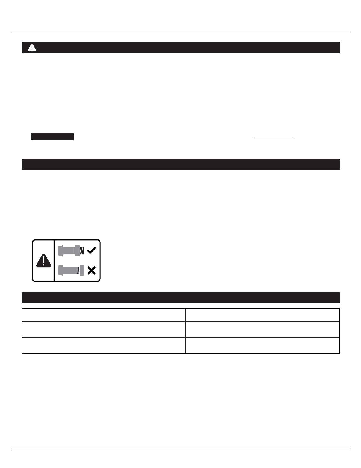
4. The Nylon Nut should thread onto the Hex Bolt until the end of the Hex Bolt has passed through the Nylon insert
inside the Nut. Please follow this guideline every time you see this Nylon Nut icon throughout the assembly steps.
Nylon Lock Safety Nuts
Tools Required For Assembly
WARNING
PLEASE NOTE : Many of the parts and hardwares listed on the parts list are already pre-assembled or
installed on the unit.
Tool Description/Purpose
Ruler (with both Metric and English measurements)
QTY: 1
Use to measure the length or size of hardware including
bolts to ensure you are using the correct part.
Adjustable or at wrenches
QTY: 2
Use to securely install parts including nuts and bolts.

BRT5350 / BRT6530 Page
4
Part Listing
The following parts list describes all of the parts illustrated in the exploded diagram on the following page.
PLEASE NOTE: most of these parts are already pre-assembled on your unit.
# Description
01 Main Frame
02 Center Post
03 Left Pedal Tube
04 Right Pedal Tube
05 Left Coupler Bar
06 Right Coupler Bar
07 Pedal Connect Joint
08 Seat Post
09 Seat Cushion Frame
10 Backrest Chion Frameu
11 Left Rear Handle Bar
12 Right Rear Handle Bar
13 Pulse Handle Bar
14 U Bracket
15 Left Handle Bar
16 Right Handle Bar
17 Front Stabilizer
18 Rear Stabilizer
19 Axle
20 Crank
21 Hex Bolt (M8x40 mm)
22 Hex Bolt (M8x45 mm)
23 Hex Bolt (M8x60 mm)
24 Hex Bolt (M8x105 mm)
25 Bolt (M8x15 mm)
26 Bolt (M8x20 mm)
27 Bolt (M8x45 mm)
28 Bolt (M10x58 mm)
29 Bolt (M8x30 mm)
30 Carriage Bolt (M8x70 mm)
31 Pedal Hinge Bolt (1/2"x97 mm)
32 Screw (M5x12 mm)
33 Washer (M8)
34 Washer (M10)
35 Wavy Washer (Ø16 mm)
36 Wavy Washer (Ø19 mm)
37 D Shape Washer
38 Spring Washer (M8)
39 Arc Washer (M8)
40 Nylon Nut (M8)
68 Foam Grip for Handle Bar
69 Monitor
70 Hand Pulse
71 Main Sensor Wire (Upper)
72 Main Sensor Wire (Lower)
73 Left Foot Pedal
74 Right Foot Pedal
75 Mat
76 Tool 1
77 Tool 2
78 Adapter
79 Screw
80 Big Washer (M8)
Washer (M10)
81
# Description
41 Nylon Nut (M10)
42 Nylon Nut (1/2")
43 Cap Nut (M8)
44 Bushing
45 Left Pedal
46 Right Pedal
47 Rectangular End Cap (25x40 mm)
48 Rectangular End Cap (25x50 mm)
49 Square End Cap (38 mm)
50 Round Cap (22 mm)
51 Round Cap (25 mm)
52 Round Cap (30 mm)
53 Spring Loaded Knob (M16)
54 Knob Bolt (M8)
55 Lock Knob (M10)
56 Pop-pin (Ø8)
57 Round Cap
58 Sleeve
59 Plastic Bushing (Ø25 mm)
60 Plastic Bushing (Ø32 mm)
61 Pulse Handle Bar Cover
62 End Cap for Front Stabilizer
63 End Cap for Rear Stabilizer
64 Seat Cushion
65 Backrest Cushion
66 Foam Grip for Pulse Handle Bar
67 Foam Grip for Rear Handle Bar
Page
5
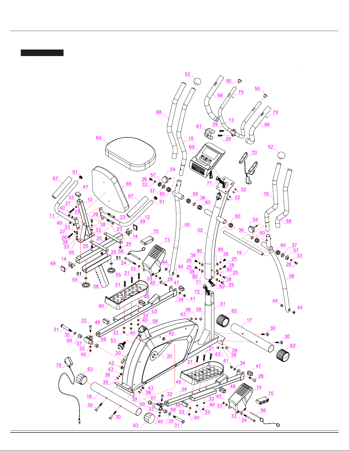
Exploded View
The following diagram is provided to help you familiarize yourself with the parts and hardware that will be used during the
assembly process.
: : Not all of the parts and hardware you see here will be used while you are assembling the machine
because some of these items are already pre-installed. Please use this page only as a reference guide for parts and
hardware.
PLEASE NOTE
BRT5350 / BRT6530
BRT5350 / BRT6530 Page
6
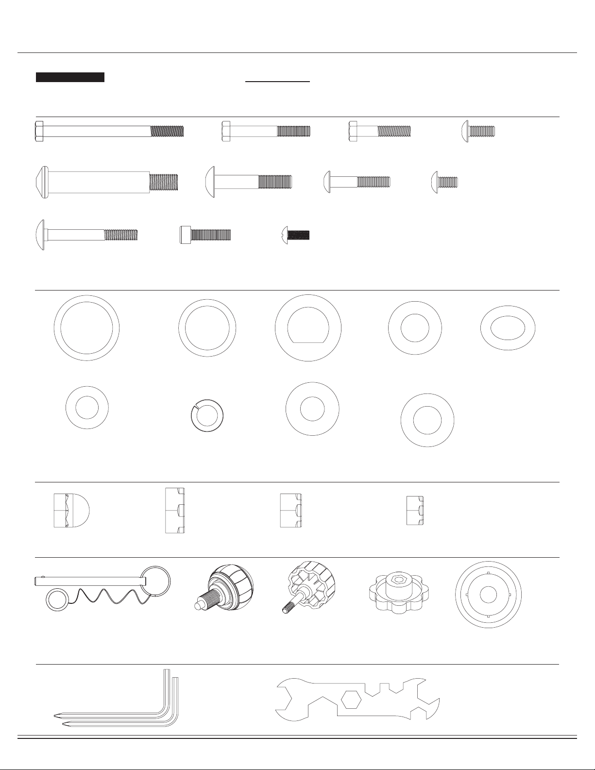
Hardware and Tool List
The following hardware is used to assemble your unit. Please take a moment to familiarize yourself with these items.
PLEASE NOTE: Most of these parts are already pre-assembled on your unit. Do not be alarmed if you see parts on this
page that are not included in your hardware packet.
Washers
#38 Spring Washer (M8)
[12 pieces]
[6 pieces pre-assembled]
#36 Wavy Washer (Ø19mm)
[2 pieces]
#35 Wavy Washer (Ø16mm)
[2 pieces]
#37 D Shape Washer (19mm)
[2 pieces]
#34 Washer (M10)
[2 pieces]
#33 Washer (M8)
[20 pieces]
[2 pieces pre-assembled]
#39 Arc Washer (M8)
[4 pieces]
[4 pieces pre-assembled]
#80 Big Washer (M8)
[6 pieces]
[6 pieces pre-assembled]
Nuts
#81 Washer (M10)
[2 pieces]
[2 pieces pre-assembled]
Bolts
Others
Tools (Included)
#24 Hex Bolt (M8x105mm)
[2 pieces]
#31 Pedal Hinge Bolt (1/2"x97mm)
[2 pieces]
#30 Carriage Bolt (M8x70mm)
[4 pieces]
#43 Cap Nut
[4 pieces]
#77 Tool 2 (5mm)
[2 pieces]
#76 Tool 1
[2 pieces]
#56 Pop-pin
[2 pieces]
#53 Spring Loaded Knob
(M16)
[1 piece pre-assembled]
#54 Knob (M8)
[2 pieces pre-assembled]
#55 Lock Knob (M10)
[2 pieces pre-assembled]
#57Axle Cover
[2 pieces]
#42 Nylon Nut (1/2")
[2 pieces]
#41 Nylon Nut (M10)
[2 pieces]
#40 Nylon Nut (M8)
[12 pieces]
[2 pieces pre-assembled]
#29 Bolt (M8x30mm)
[2 pieces]
#32 Screw (M5x12mm)
[4 pieces]
#28 Bolt (M10x58mm)
[2 pieces]
#27 Bolt (M8x45mm)
[2 pieces]
#26 Bolt (M8x20mm)
[4 pieces]
#25 Bolt (M8x15mm)
[10 pieces]
[6 pieces pre-assembled]
#23 Hex Bolt (M8x60mm)
[2 pieces]
#21 Hex Bolt (M8x40mm)
[6 pieces]
BRT5350 / BRT6530 Page
7
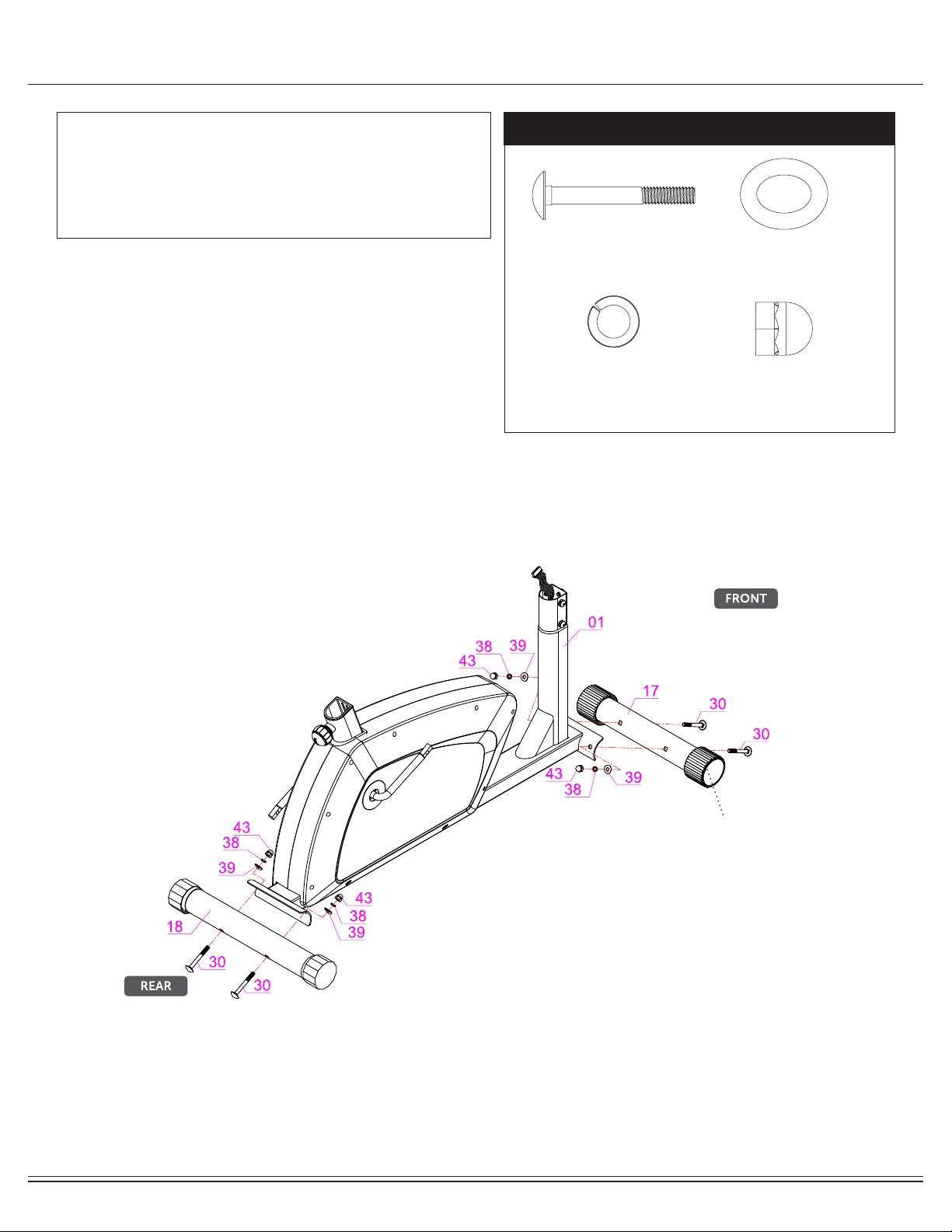
Assembly STEP 1
Secure the Rear Stabilizer (#18) to the Main Frame (#01)
using two Carriage Bolts (#30) followed by two Arc Washers
(#39), two Spring Washers (#38), and two Cap Nuts (#43).
FRONT STABILIZER ASSEMBLY
Secure the Front Stabilizer (#17) to the Main Frame (#01)
using two Carriage Bolts (#30) followed by two Arc Washers
(#39), two Spring Washers (#38), and two Cap Nuts (#43).
Note:
Please Note that the Front Stabilizer (#15) has end caps that
spin for ease of relocating the unit.
REAR STABILIZER ASSEMBLY
Hardware Required
Front Roller
NOTE BEFORE STARTING THE ASSEMBLY PROCESS :
To avoid misalignment due to over-tightening, please do not use a
wrench and use only hand-tightening for now to ensure
easy assembly.
Wrench-tightening should be performed after all parts are assembled
to ensure all nuts, bolts, and parts are tightly secured before use. #30 Carriage Bolt (M8x70mm)
[4 pieces]
#38 Spring Washer (M8)
[4 pieces] #43 Cap Nut
[4 pieces]
#39 Arc Washer (M8)
[4 pieces]

BRT5350 / BRT6530 Page
8
Assembly STEP 2
Connect the Main Sensor Wire (Lower)(#72) to the Main
Sensor Wire (Upper) (#71).
Remove the Bolts (#25), Spring Washers (#38) and Big
Washers (#80) that are pre-assembled on the Main Frame
(#01) and set them aside as they will be used later in this step.
Being careful not to pinch any wires, slide the Center Post
(#02) onto the Main Frame (#01) and secure it using the
previously removed six Bolts (#25), six Spring Washers (#38),
and six Big Washers (#80) as shown in drawing below.
Hardware Required
#25 Bolt (M8x15mm)
[6 pieces]
#38 Spring Washer (M8)
[6 pieces]
#80 Big Washer (M8)
[6 pieces]

BRT5350 / BRT6530 Page
9
Assembly STEP 3
Hardware Required
Referring to the drawing below, insert the Axle (#19) through the
horizontal stems on the Center Post (#02). Then, on the left side of
the Axle (#19) -- in the following order, slide on: one Wavy Washer
(#36) followed by the Left Coupler Bar (#05), one D Shape Washer
(#37), one Round Cap (#57), one Washer (#33), and secure using
one Bolt (#26).
On the opposite side of the Axle (#19), assemble -- in the following
order: one Wavy Washer (#36) followed by the Right Coupler Bar
(#06), one D Shape Washer (#37), one Round Cap (#57),
one Washer (#33), and secure using one Bolt (#26).
Attach the Right Pedal Tube (#04) onto the Crank (#20) as
illustrated and secure by inserting from the outer edge of the Right
Pedal Tube (#04), one Pedal Hinge Bolt (#31) and one Wavy Washer
(#35). Secure from the inner edge (behind the Crank(#20)) with one
Nylon Nut (#42).
*** PLEASE DO NOT tighten the hardwares until steps below has
been completed. This will allow you to align the holes for proper
and smooth assembly.***
Repeat this process on the other side using the Left Pedal Tube (#03).
Using the drawings as a reference, attach the free end of the bottom
of the Right Coupler Bar (#06) to the front of the Right Pedal Tube
(#04) by aligning the holes. After the holes are aligned, insert one Bolt
(#28) through the Right Pedal Tube (#04), the Right Coupler
Bar (#06) and secure using one Washer (#34) followed by
one Nylon Nut (#41).
Repeat this process on the other side using Left Coupler Bar (#05)
and Left Pedal Tube (#03).
***NOW, you may tighten the hardwares on both sides.***
#36 Wavy Washer
(Ø19mm)
[2 pieces]
#37 D Shape Washer
(19mm)
[2 pieces]
#57Axle Cover
[2 pieces]
#33 Washer (M8)
[2 pieces]
#26 Bolt (M8x20mm)
[2 pieces]
#42 Nylon Nut
(1/2")
[2 pieces]
#41 Nylon Nut
(M10)
[2 pieces]
#34 Washer (M10)
[2 pieces]
#31 Bolt (1/2"x97mm)
[2 pieces]
#28 Bolt (M10x58mm)
[2 pieces]
#35 Wavy Washer
(Ø16mm)
[2 pieces]

BRT5350 / BRT6530 Page
10
Assembly STEP 4
Hardware Required
Attach the Left/Right Pedals (#45/#46) onto the Left/Right
Pedal Tubes (#03/#04) as shown in the drawing below using a
total of six Hex Bolts (#21), six Washers (#33), and six Nylon
Nuts (#40).
On the left side, attach the Left Foot Pedal (#73) to the front of
Left Pedal Tube (#03) using one Hex Bolt (#24) through one
Washer (#33) and Pop-pin (#56) safety ring and secure with
one Washers (#33) and one Nylon Nut (#40).
Then insert a Pop-pin (#56) into the front hole of the Left Foot
Pedal (#73).
Repeat this process on the other side.
Note: Care should be used when mounting or dismounting the machine.
Before mounting or dismounting, move the pedal on the mounting or
dismounting side to its lowest position and bring the machine to a
complete stop. This unit is not equipped with a free-wheel. Pedal speed
should be reduced in a controlled manner. Front Foot Pedal with 3 settings
#21 Hex Bolt (M8x40mm)
[6 pieces]
#33 Washer (M8)
[10 pieces]
#40 Nylon Nut (M8)
[8 pieces]
#24 Hex Bolt (M8x105mm)
[2 pieces]
#56 Pop-pin
[2 pieces]
BRT5350 / BRT6530 Page
11
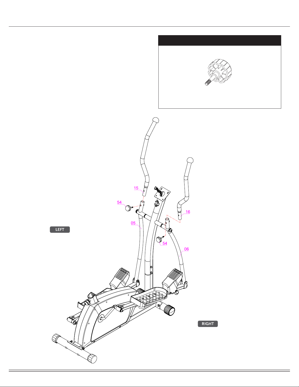
Assembly STEP 5
Hardware Required
Please remove the two Knob Bolts (#54) that are pre-assembled
on the Left/Right Coupler Bars (#05/#06).
On the left side, insert Left Handle Bar (#15) into the opening at
the tip of Left Coupler Bar (#05). Align the holes of the Left Handle
Bar (#15) and Left Coupler Bar (#05) and secure by using one
Knob Bolt (#54) through.
Repeat this process on the other side using Right Handle Bar
(#16) and Right Coupler Bar (#06). #54 Knob (M8)
[2 pieces]
BRT5350 / BRT6530 Page
12
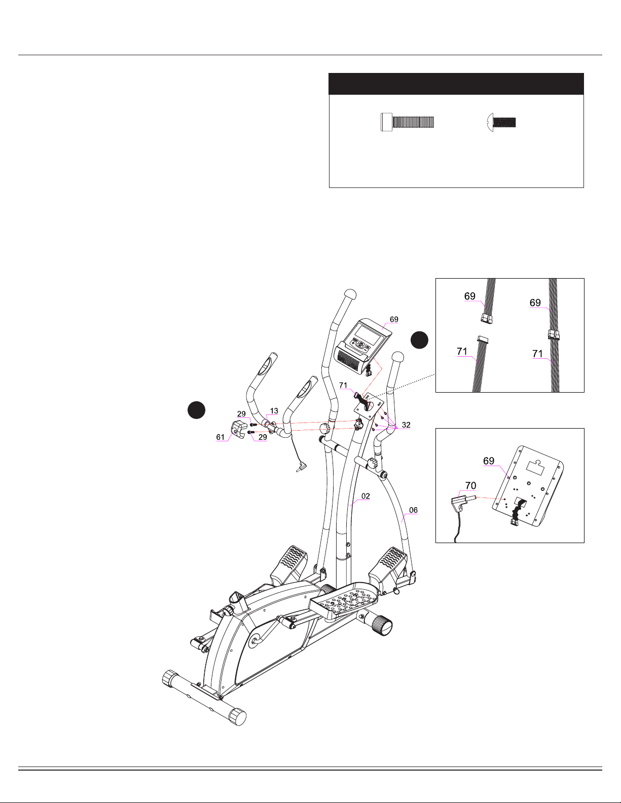
Assembly STEP 6
Hardware Required
A. PULSE HANDLEBAR
Install the Pulse Handle Bar (#13) onto the rear side of the Center
Post (#02) as shown in the illustration below using two Bolts (#29).
Please ensure the wire of the Handle Pulse (#70) is free and clear,
avoiding pinching it during this assembly step. You will need to
connect this wire to the Monitor (#69) later.
B. COMPUTER
Remove the four Screws (#32) that are pre-assembled on the
Monitor (#69). Set them aside as they will be used later in this
process. With the help of an assistant, connect the Main Sensor Wire
(#71) to the corresponding wire on the Monitor (#69)(diagram A).
Connect the end of Hand Pulse (#70) to the Monitor (#69) by inserting
it into the back socket as illustrated below (diagram B).Being careful
not to pinch/damage any of the wires, attach the Monitor (#69) to the
bracket on the Center Post (#02) by using the four Screws (#32) that
were previously removed.
I
II
A.
B.
#29 Bolt (M8x30mm)
[2 pieces]
#32 Screw (M5x12mm)
[4 pieces]
BRT5350 / BRT6530 Page
13
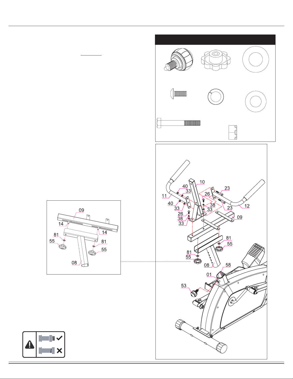
Assembly STEP 7
Hardware Required
Start wih loosen the pre-assembled Spring Loaded Knob (#53) and
pull back slightly on it so that you may proceed to insert the Seat Post
(#08) into the opening of the post that is protruding from the Main
Frame (#01) down a minimum of four inches so that the corresponding
holes can engage. Screw in the Spring Loaded Knob (#53) through the
Main Frame (#01) and then through any one of the holes located on
the Seat Post (#08).
Note:
The Spring Loaded Knob (#53) has a safety feature that allows you to
loosen it by turning it counter-clockwise three times as you pull it out-
ward. This knob can be loosened to adjust the seat height. Adjust the seat
height and then release the knob back in. Tighten the knob by turning
clockwise.
Slide the Seat Cushion Frame (#09) onto the trough of the Seat Post
(#08) as shown below. Secure using two Lock Knobs (#55) through
two Washers (#81).
Attach Backrest Cushion Frame (#10) to the Seat Cushion Frame
(#09) and secure by using two Bolts (#26), two Spring Washers (#38),
two Washers (#33).
With the help of an assistant, align the four of the Left Rear
Handle Bar (#11) and Right Rear Handle Bar (#12) to the holes on the
Backrest Cushion Frame (#10) and secure all using the two Hex Bolts
(#23), followed by two Washers (#33), and two Nylon Nuts (#40).
#55 Lock Knob (M10)
[2 pieces] #81 Washer (M10)
[2 pieces]
#53 Spring Loaded Knob
(M16)
[1 piece]
#26 Bolt (M8x20mm)
[2 pieces] #38 Spring Washer (M8)
[2 pieces]
#33 Washer (M8)
[4 pieces]
#23 Hex Bolt (M8x60mm)
[2 pieces]
#40 Nylon Nut (M8)
[2 pieces]

Page
14
Assembly STEP 8
Hardware Required
Attach the Seat Cushion (#64) to the horizontal bar of the
Seat Cushion Frame (#09) and secure from the bottom using
four Bolts (#25).Then, attach the Backrest Cushion (#65)
to the Backrest Cushion Frame (#10) and secure using two
Bolts (#27) through two Washers (#33).
#33 Washer (M8)
[2 pieces]
#25 Bolt (M8x15mm)
[4 pieces]
#27 Bolt (M8x45mm)
[2 pieces]
BRT5350 / BRT6530

Page
15
Assembly STEP 9
Hardware Required
THE ASSEMBLY PROCESS IS NOW COMPLETE.
However, for your own safety, please make sure to read this entire Owner’s Manual which
includes safety instructions and warnings, as well as any safety/warning labels axed to the
product before use. For your safety , please visually and functionally inspect and test the unit
after assembly is complete.
Plug in the Adapter (#76) male plug into the female socket
located at the rear end of the shroud and then plug in the
Adapter (#76) to the electrical outlet to start your workout.
No Hardware Required
NOTE :
Please wrench-tightened all parts now that assembly is completed to
ensure all nuts, bolts, and parts are tightly secured before use.
BRT5350 / BRT6530

Computer Operation
26
10
3for a total of 24 resistance levels.
PageBRT5350 / BRT6530 16
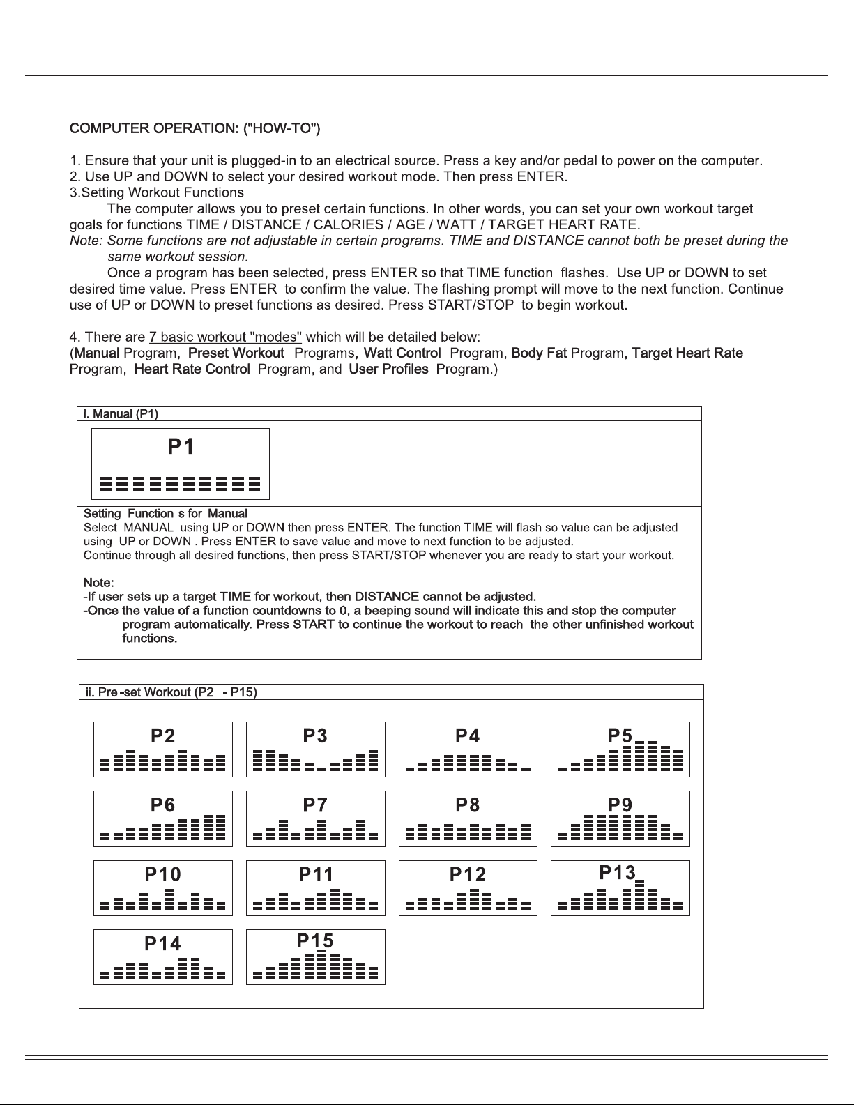
Computer Operation
PageBRT5350 / BRT6530 17

Computer Operation
14
PageBRT5350 / BRT6530 18
This manual suits for next models
1
Table of contents
Other Body Champ Elliptical Trainer manuals


