Body Champ BR3070 User manual

BR3070
OWNER’S MANUAL
* This item is for consumer use only and it is not meant for commercial use.
OWNER’S MANUAL
* This item is for consumer use only and it is not meant for commercial use.

BR 3070 Page 1
General Information
Warranty
Body Flex Sports warrants your product for
a period of 1 year for the frame and 90 days
on all parts if the item is used for the intended
purpose, properly maintained and not used
commercially. Any alterations or incorrect
assembly of the product will void this warranty.
Proof of purchase must be presented for any
warranty validation (no exceptions). This
warranty applies to the original purchaser only
and is not transferable.
This warranty does not cover abuse or defects
caused during use, storage or assembly.
During the warranty period, Body Flex Sports
reserves the right to:
a). provide replacement parts to the
purchaser in an effort to repair the item.
b). repair the product returned to our
warehouse (at the purchaser’s cost).
c). replace the product if neither of the two
previously mentioned actions effect repair.
This warranty does not cover normal wear and
tear on upholstery.
Questions
If you have any questions concerning the
assembly of your item or if any parts are
missing, please DO NOT RETURN THE
ITEM TO THE STORE OR CONTACT THE
RETAILER. Our dedicated customer service
staff can help you with any questions you may
have regarding the assembly of this unit and
can also mail you replacement parts.
Customer Support
Customer Support is open 9:00 a.m. to 5:00
p.m. (Pacific Time) Monday through Friday.
Please contact us by any of the following
means.
Body Flex Sports, Inc.
21717 Ferrero Parkway, Walnut, CA 91789
Telephone: (888) 266 - 6789
Fax: (909) 598 - 6707
Email: info@bodyflexsports.com
Safety
Before you undertake any exercise program,
please be sure to consult with your doctor.
Frequent strenuous exercise should be
approved by your doctor and proper use
of your product is essential. Excessive or incorrect
training may result to health injuries. Please read
this manual carefully before commencing the
assembly of your product or starting to exercise.
• Please keep all children away from this item
when in use. Do not allow children to climb or
play on them when they are not in use.
• Supervise teenagers while they use this unit.
• For your own safety, always ensure that there
is at least 3 feet of free space in all directions
around your product while you are exercising.
• Regularly check to see that all nuts, bolts and
fittings are securely tightened. Periodically
check all moving parts for obvious signs of
wear or damage.
• Clean only with a damp cloth, do not use
solvent cleaners. If you are in any doubt, do
not use your product; contact CUSTOMER
SUPPORT.
• Before use, always ensure that your product
is positioned on a solid, flat surface. If
necessary, use a rubber mat underneath to
reduce the possibility of slipping.
• Always wear appropriate clothing and
footwear such as training shoes when
exercising. Do not wear loose clothing that
could become caught in moving parts during
exercise.
• Do not use this unit if it is not functioning
properly or if it is not fully assembled.
• Do not use this unit for commercial purposes.
This unit is for home use only.
Storage and Use
Your product is intended for use in clean
dry conditions. You should avoid storage in
excessively cold or damp places as this may
lead to corrosion and other related problems.
Weight Limit
Your product is suitable for users weighing:
250 pounds or less.
• Before use, you must read and understand all
instructions & warnings stated in this Owner’s
Manual as well as posted on the equipment.
• It is the facility owner’s responsibility to properly
instruct users on the proper operation of the
equipment and to warn them of the potential
hazards.
• If at any time during exercise you feel faint, dizzy
or experience pain, stop and consult your
physician.
Assembling Tools
- Ruler with both metric and English measurements
- 2 x Adjustable Wrenches
- 1 x Philips (”Crosshead”) Screw Driver
•
Any adjustment devices that could interfere with
the user's movement on this unit should not be
left projecting.
#12. Carriage Bolt
(M10×57 mm)
[4 Pieces]
#38L. Left Pedal Hinge Bolt
#38R. Right Pedal Hinge Bolt
#13. Arc Washer
(M10)
[4 Pieces]
#30. Hex Bolt
(M8×55 mm)
[2 Pieces]
#33. Hex Bolt
(M10×45 mm)
[4 Pieces]
#45. Carriage Bolt
(M8×40 mm)
[4 Pieces]
#51. Bolt
(M8×30 mm)
[2 Pieces]
pre-assemble
#55. Screw
(M4X12 mm)
[2 Pieces]
pre-assemble
#16. Bolt
(M8×16 mm)
[4 Pieces]
pre-assemble
#24. Hex Bolt
(M8×15 mm)
[2 Pieces]
pre-assemble
#41. Spring Washer
(Φ13×B2)
[2 Pieces]
#31. Washer
(M8,t1.5)
[2 Pieces]
#34. Washer
(M10)
[4 Pieces]
#25. Washer
(M8, t2.0)
[2 Pieces]
#52. Spring Washer
(M8)
[4 Pieces]
pre-assemble
#56. Arc Washer
(M8,R25)
[4 Pieces]
pre-assemble
#44. Arc Washer.
(M8, R16)
[4 Pieces]
#62. Special Washer
(D17×0.3)
[2 Pieces]
#54. Special Washer
(Φ20)
[2 Pieces]
pre-assemble
#14. Cap Nut
(M10)
[4 Pieces]
#32. Nylon Nut
(M8)
[2 Pieces]
#35. Nylon Nut
(M10)
[4 Pieces]
#42L. Left Nylon Nut
#42R. Right Nylon Nut
#58. Nut
(M8)
[4 Pieces]
S8 [1Piece] S6 [1Piece] S13-14 [1Piece] S17-19 [1Pieces]
S10-13-14-15-17 [1Piece]
pre-assemble
Bolts
Washers
Nuts
Tools
[each 1 Piece]
[each 1 Piece]
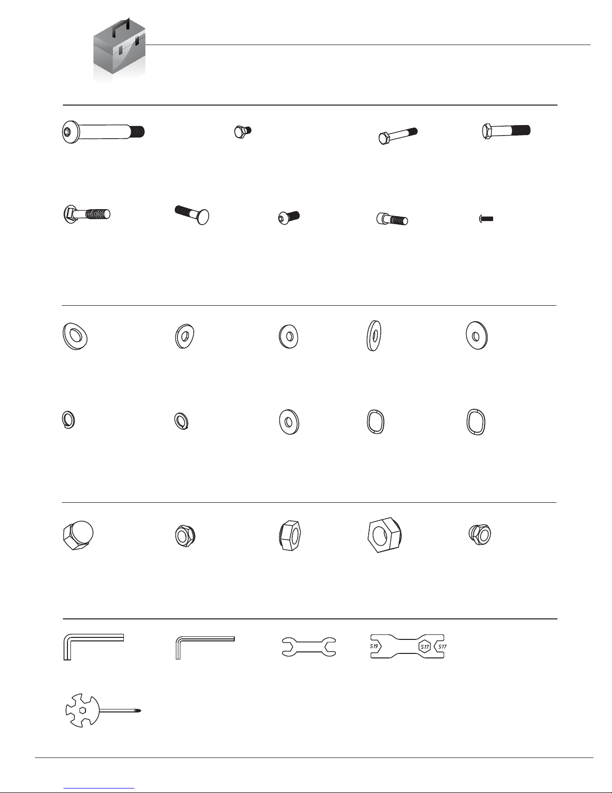
Hardware & Tool List
The following hardware is used to assemble your unit. Please take a moment to familiarize yourself with these items.
PLEASE NOTE: some of these parts may have already been pre-assembled on your unit.
BR 3070 Page 2

Page 3
BRM 3670 Stride Cycle Page ?
# Description # Description
01 Main Frame 35 Nylon Nut (M10)
02 Front Post 36 Bolt Cap (S16 )
03 Front Stabilizer 37 Hex Bolt (M10×50 mm)
04 Rear Stabilizer 38L/38R Left/Right Pedal Hinge Bolt
05L/05R Left/Right Pedal Arm 39 Bushing (Ф24×20×Ф16.1 )
06L/06R Left/Right Coupler Bar 40L/40R Pedal Connection Joint
07L/07R Left/Right Handlebar 41 Spring Washer (Φ13×B2)
08 Pulse Handlebar 42L/42R Left/Right Nylon Nut
09 Monitor 43 Bolt Cap (S19)
10L/10R Left/Right Pedal 44 Arc Washer (M8, R16)
11 End Cap for Front Stabilizer 45 Carriage Bolt (M8×40 mm )
12 Carriage Bolt (M10×57 mm) 46 End Cap
13 Arc Washer (M10) 47 Foam of Handlebar
14 Cap Nut (M10) 48 Foam of Pulse Handlebar
15 End Cap for Rear Stabilizer 49 End Cap (Φ25×1.5)
16 Bolt (M8×16 mm) 50 Handle Pulse Wire (Lower)
17 Tension Controller 51 Bolt (M8×30 mm)
18a/18b Main Sensor Wire (Middle) 52 Spring Washer (M8)
19 Tension Wire 53 Cover of Handlebar
20 Main Sensor Wire (Lower) 54 Special Washer (Φ20)
21 Screw (M5X45 mm) 55 Screw (M4X12 mm)
22L/22R Crank 56 Arc Washer (M8,R25)
23 Bolt Cap (S14 ) 57 Bolt Cap (S13 )
24 Hex Bolt (M8×15 mm) 58 Nut (M8)
25 Washer (M8, t2.0) 59 Washer (M5)
26 Bushing (Φ 32×2.5) 60 Cover of Tension Controller
27 Front Post Axle 61 Bushing (Φ14*10*Φ10.1 )
28 End Cap (Φ28×1.5) 62 Special Washer (D17×0.3)
29 End Cap (□40×25×1.5 ) 63 Screw (ST3×10 mm)
30 Hex Bolt (M8×55 mm) 64 Shroud 1
31 Washer (M8,t1.5) 65 Shroud 2
32 Nylon Nut (M8) 66 Main Sensor Wire (Upper)
33 Hex Bolt (M10×45 mm) 67 Handle Pulse Wire (Upper)
34 Washer (M10)
Parts Listing
The following parts list describes all of the parts illustrated on the
exploded diagram on the following page. Please note, most of
these parts are already pre-assembled on your unit.
0703RB

Page 4
Exploded Diagram
The following diagram is provided to help you familiarize yourself with the parts and
hardware that will be used during the assembly process. Please note that not all of the
parts and hardware you see here will be used while you are assembling the machine
because some of these items are already pre-installed. Please continue to the next
page to begin the assembly process and use this page only as a reference guide for
parts and hardware.
BR 3070
Page 5
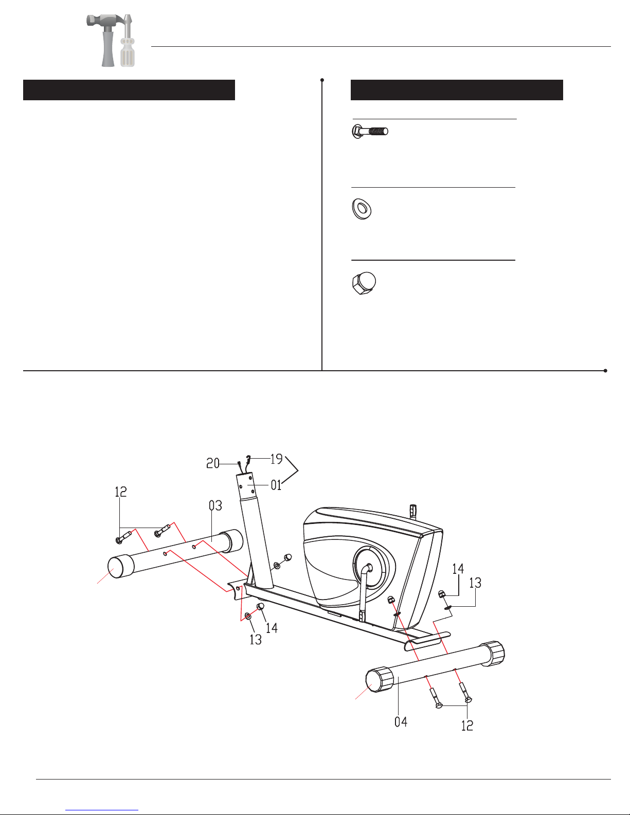
Hardware Required
#12. Carriage Bolt
(M10×57 mm)
[4 Pieces]
#13. Arc Washer (M10)
[4 Pieces]
[4 Pieces]
Bolts
Washers
Nuts
A s s e m b l y S t e p 1
#14. Cap Nut
(M10)
0703RB
Make sure these two wires are hanging out before
proceeding to the next step. If they have fallen
inside the tube, use a bent wire to “fish” them out.
Spinning
End Caps
Height Adjustable
End Caps
With the help of an assistant, attach the Front Stabilizer (#03)
to the front of the Main Frame (#01). Insert two Carriage Bolts
(#12) through the Front Stabilizer (#03) followed by the front
of the Main Frame (#01). Secure them together using two Arc
Washers (#13) and two Cap Nuts (#14).
Now attach the Rear Stabilizer (#04) to the rear of the Main
Frame (#01). Insert two Carriage Bolts (#12) through the
Rear Stabilizer (#04) followed by the rear of the Main Frame
(#01). Secure them together using two Arc Washers (#13)
and two Cap Nuts (#14).
Please note: The Front Stabilizer (#03) has end caps that
spin for ease of relocating the unit and the Rear Stabilizer
(#04) has height adjustable end caps for leveling of the unit.
Assembly Instructions
Page 6
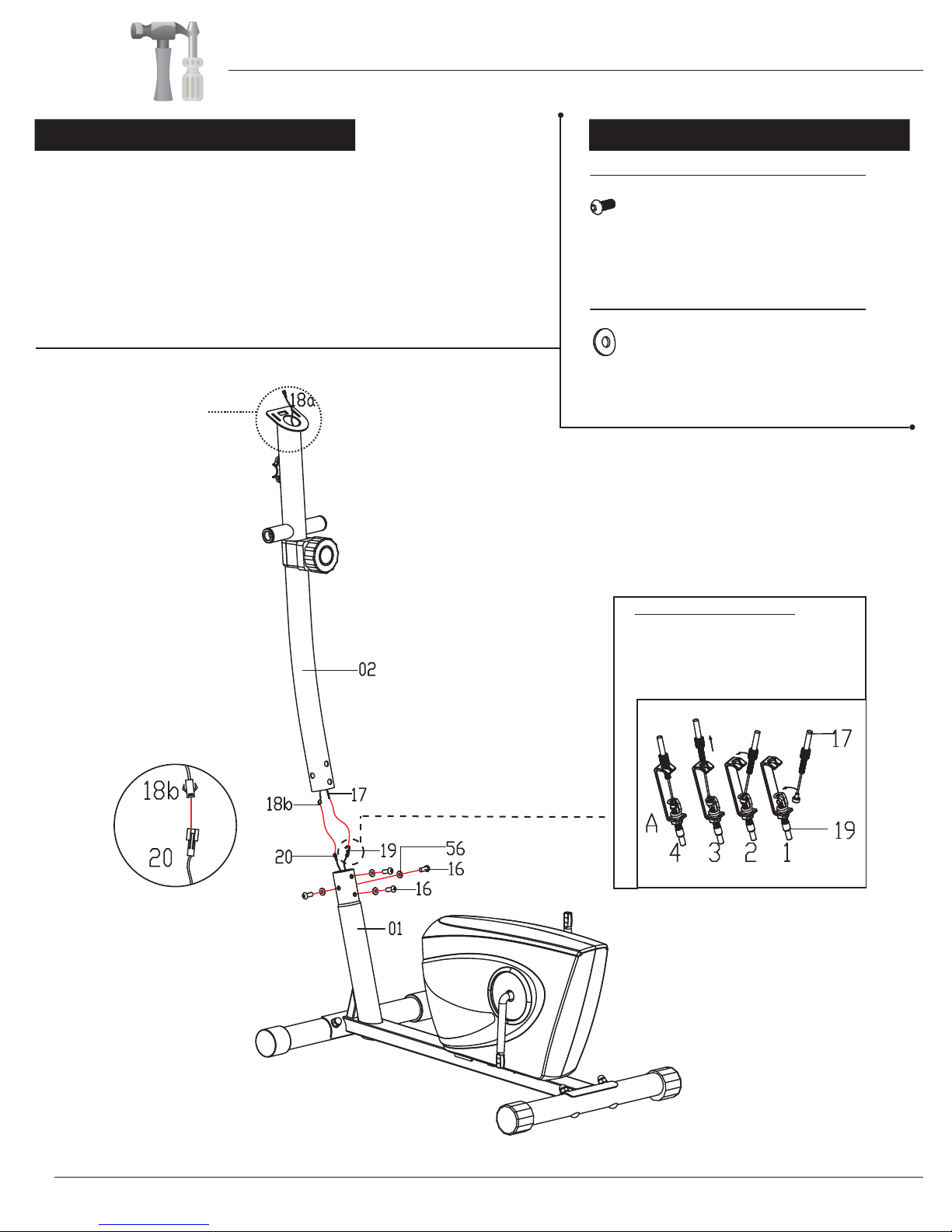
Hardware Required
Make sure this wire is
hanging out before
assembling the Front
Post (#02).
#16. Bolt
(M8×16 mm)
[4 Pieces]
#56. Arc Washer (M8,R25)
[4 Pieces]
Bolts
Washers
A s s e m b l y S t e p 2
Remove four Bolts (#16) and four Arc Washers (#56) that were
pre-assembled on the Main Frame (#01) and set them aside as they
will be used in a later process.
Connect the Main sensor Wire (Middle) (#18b) to the Main Sensor
Wire (Lower) (#20) and then follow the instructions in the diagram
below to connect the Tension Wire (#19). After connecting the Tension
Wire (#19) to the Tension Controller (#17) slide the Front Post (#02)
onto the Main Frame (#01) and secure it using four Bolts (#16) and four
Arc Washers (#56) that were previously removed.
TENSION WIRE ASSEMBLY
Insert the tip of the Tension
Controller (17) wire into the Tension
Wire (19) head at an angle. Tilt the
Tension controller (17) wire into the
crevice and then pull upward.
Assembly Instructions
0703RB
Page 7
BR 3070
Assembly Instructions
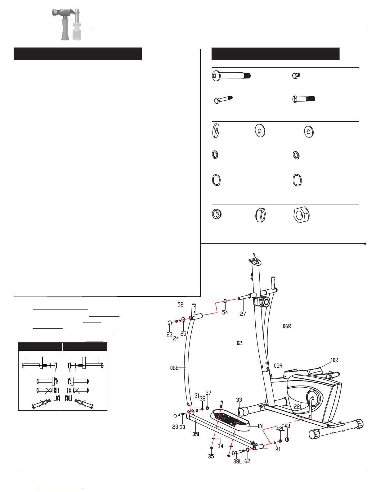
Hardware Required
Bolts
Washers
Nuts
[each 1 Piece]
Hardware Required
Please refer to the diagram below and pay special attention to corresponding
left & right side parts. Misplacing parts during assembly will lead to incorrect
assembly and may result in serious injury.
Pedal Hinge Bolt (#38L) and CLOCKWISE to tighten
Left Nylon Nut (#42L) with BLACK inner nylon ring.
A s s e m b l y S t e p 3A s s e m b l y S t e p 3
#38L/R. Left/Right Pedal Hinge Bolt
[each 1 Piece]
#30. Hex Bolt
(M8×55 mm)
[2 Pieces]
#33. Hex Bolt
(M10×45 mm)
[4 Pieces]
#24. Hex Bolt (M8×15 mm)
[2 Pieces]
#41. Spring Washer (Φ13×B2)
[2 Pieces]
#31. Washer
(M8,t1.5)
[2 Pieces]
#34. Washer (M10)
[4 Pieces]
#25. Washer
(M8, t2.0)
[2 Pieces]
#52. Spring Washer (M8)
[2 Pieces]
#62. Special Washer
(D17×0.3)
[2 Pieces]
#54. Special Washer
(Φ20)
[2 Pieces]
#32. Nylon Nut
(M8)
[2 Pieces]
#35. Nylon Nut
(M10)
[4 Pieces]
#42L. Left Nylon Nut
#42R. Right Nylon Nut
LEFT SIDE RIGHT SIDE
38L 38R
41 42L 42R41
40L
Note:
Keep the Left/Right Pedal Hinge Bolt
(#38L/38R) perfectly
straight as they go
through the Left/Right Pedal Connection
Joint (#40L/R)
and the Crank (#22L/R).
If the Left/Right Pedal Hinge Bolt (#38L/38R)
are connected to the
Crank (#22L/22R)
incorrectly,
damage to the
Left/Right Pedal Hinge Bolt
(#38L/38R) and Crank (#22L/22R)
will occur.
PLEASE NOTE:
b):Turn CLOCKWISE to tighten the Right Pedal Hinge
Bolt (#38R) and COUNTERCLOCKWISE to tighten
Right Nylon Nut (#42R) with WHITE inner nylon ring.
Remove two Hex Bolts (#24), two Spring Washers (#52), two
Washers (#25) and two Special Washers (#54) that are
pre-assembled on the Front Post Axle (#27) and set them aside
as they will be used in a later process.
Insert the Front Post Axle (#27) through the Front Post (#02).
Make sure the Front Post Axle (#27) is centered. If you encounter
too much friction, try using WD40 or Vaseline asa lubricant.
Slide one Special Washer (#54) onto the left side of the Front Post
Axle (#27) then followed by Left Coupler Bar (#06L). Secure them
together by hand tighten one Hex Bolt (#24), one Spring Washer
(#52) and one Washer (#25) that were previously removed.
Align and attach the left Pedal Connection Joint (#40L) on the
Left Pedal Arm (#05L) to the left Crank (#22L). Insert Left Pedal
Hinge Bolt (#38L) through a Special Washer (#62) followed by
left Pedal Connection Joint (#40L) and left Crank (#22L). Screw
the Left Pedal Hinge Bolt (#38L) tightly into the left Crank (#22L)
by turning COUNTERCLOCKWISE and then secure it by hand tighten
one
Spring
Washer
(#41) and one Left Nylon Nut (#42L) by turning it
CLOCKWISE.
Align and attach the Left Coupler Bar (#06L) to the Left Pedal
Arm (#05L). Hand Tighten them together using a Hex Bolt (#30),
a Washer (#31) and a Nylon Nut (#32).
At this point secure the Hex Bolts (#24), Hex Bolt (#30) and Left
Nylon Nut (#42L) that were hand tightened previously.
Attach Bolt Cap (#23) to the end of Hex Bolt (#24) and Hex Bolt
(#30). Attach Bolt Cap (#43) to the end of Left Nylon Nut (#42L).
Attach Bolt Cap (#57) to the end of Nylon Nut (#32).
Attach the Left Pedal (#10L) to the Left Pedal Arm (#05L) and
secure them together using two Hex Bolts (#33), two Washers
(#34) and two Nylon Nuts (#35).
Repeat this process on the other side.
a):Turn COUNTERCLOCKWISE to tighten the Left

Page 8
Assembly Instructions
Hardware Required
#45. Carriage Bolt
(M8×40 mm)
[4 Pieces]
#51. Bolt
(M8×30 mm)
[2 Pieces]
#52. Spring Washer
(M8)
[2 Pieces]
#44. Arc Washer.
(M8, R16)
[4 Pieces]
#58. Nut (M8)
[4 Pieces]
Bolts
Washers
Nuts
A s s e m b l y S t e p 4
Insert the Left/Right Handlebars (#07L/07R) onto
the open ends of the two Coupler Bars
(#06L/06R).
Secure the
Left/Right Handlebars (#07L/07R) using
two
Carriage Bolts (#45), two Arc Washers (#44) and
Nuts (#58).
Install the Pulse Handle Bar (#08) onto the front side
of the Front Post (#02) using two Bolts (#51) and two
Spring Washers (#52) that were previously removed.
Slide the Cover of Handlebar (#53) over the Pulse
Handlebar (#08).
Feed the Handle Pulse Wire (Lower) (#50) through
the neck of the Front Post (#02) until they are sticking
out of the opening. You’ll need to connect the Monitor
(#09) Later.
Remove
two
Bolts (#51) and two Spring Washers
(#52) that were pre-assembled on the Front Post
(#02) and set them aside as they will be used in a
later process.
two
Feed the Handle Pulse Wire
(Lower) (#50) through the
neck of the Front Post (#02)
until they are sticking out of
the opening.
0703RB
Page 9
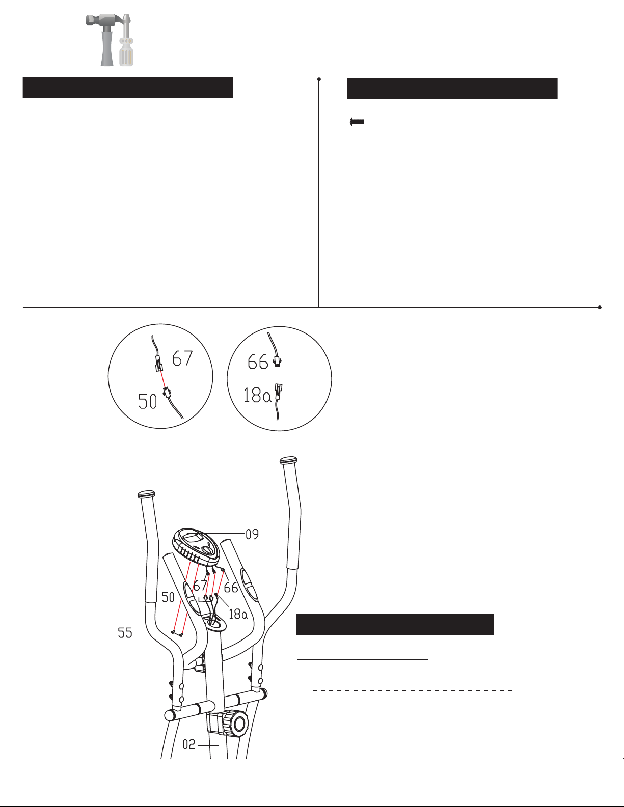
A s s e m b l y S t e p 5
Connect the Handle Pulse Wire (Lower) (#50) to the
Handle Pulse Wire (Upper) (#67) and connect the Main
Sensor Wire (Middle) (#18a) to the Main Sensor Wire
(Upper) (#66). Secure the Monitor (#09) to the bracket
on the Front Post (#02) with two Screws (#55) that were
Hardware Required
#55. Screw (M4X12 mm)
[2 Pieces]
The assembly process is complete; however, please
read all safety instructions in this manual as well as
any safety/warning labels on the unit before use.
Please ensure all nuts, bolts and knobs are securely
tightened before using the unit.
Removed two Screws (#55) that are pre-assembled on
the back of the Monitor (#09) and set them aside as they
will be use d in a later process.
previously removed.
After complete assembly: If the computer
is not picking up your hand pulse signal
(or you are getting inaccurate readings),
Please refer to our “Troubleshooting”
section on Page 12 for other troubleshoot
issues.
HAND PULSE SIGNAL
Troubleshooting
BR 3070
Assembly Instructions

Computer Operation
BR 3070 Page 10
FUNCTION MARK:
1. Lift off the battery cover and place two SIZE-AAA batteries into the
battery housing on back of monitor with the +/- sides installed correctly.
2. Please ensure batteries are correctly positioned and battery springs are in proper
contact with batteries.
3. Replace battery cover and ensure it is tightly closed.
4. Battery life is approx. 1 year under normal usage.
5. If the display is illegible or only partial segments appear, remove batteries and wait
15 seconds before reinstalling.
6. Removing the batteries will erase the computer memory.
*NOTE: Please refer to our “TROUBLESHOOTING” page in this manual if you have
any trouble with the LCD Computer Monitor or Pulse/Recovery Functions.
FUNCTIONS AND OPERATIONS:
Mode or function: Explanation:
Auto On/Off & Auto As long as the machine is in motion, the monitor will
Start/Stop remain on. If the machine is not in use and/or not in
motion for over 4 minutes, the monitor will turn off and
reset all function values to zero.
Auto Scan
monitor will rotate through all 5 functions: Speed, Distance,
Time, Odometer & Calories. Each function will display for 6
seconds.
Speed Press the button until the ARROW points to “S” to display
the current speed.
Trip Distance Press the button until the ARROW points to “D” to display
the trip distance you are traveling.
Elapsed Time Press the button until the ARROW points to “T” to display
the elapsed time.
Total Distance Press the button until the ARROW points to “O” to
(Odometer) display the total accumulated distance.
Press the button until the ARROW points to “A”, the
A: Auto Scan O: Odometer (Total Distance)
S: Current Speed C: Calories Burned
D: Distance Traveled : Pulse Rate
T: Elapsed Time
BATTERY INSTALLATION/REPLACEMENT:
0:00
TIME
ODOMETER
CALORIES
PULSE
DISTANCE
SPEED
SCAN

Computer Operation
BR 3070 Page 11
Current Speed The maximum signal that can be detected is 1200
RPH
Trip Distance 0.1-999.9 Miles
Elapsed Time 0:00-99:59( Minute : Second )
Odometer 0.1-999.9 Miles
Calorie 0.1-999.9 K.cal
Pulse Rate 40-240 beats per minute
Controller 4 bit single chip microprocessor
Sensor No-contact magnetic type
Battery type 2 PCS of SIZE-AAA
Operating temperature 0℃ - +40℃ ( 32℉ - 104℉ )
Storage temperature -10℃ - +60℃ ( 14℉ - 140℉ )
Calories Press the button until theARROW points to “C” to display
the calorie consumption/calories burned.
Pulse Rate Press the button until “” appears to show your heart rate
(Pulse) in beats per minute. Place the palms of your hands
and grip lightly on both the contact pads and the monitor will
display your heartbeat rate in beats per minute (BPM) on
the LCD display.
Reset Holding the button for 3 or more seconds will reset all
functional values to zero (except Odometer). The Odometer
will reset anytime the batteries are removed & replaced.
SPECIFICATIONS:
FUNCTION
Auto Scan Every 6 seconds

Troubleshooting
If the computer is not picking up your hand pulse signal (or you are getting
inaccurate readings), please adjust the following:
1. Slightly moisten/dampen the palms with water so the sensors can detect a
pulse signal.
2. Do not grip the sensors too tightly. Only moderate pressure need be applied.
Gripping the sensors too tightly restricts and seizes detection of your pulse.
3. Remove any rings or jewelry to prevent interference.
4. Check to ensure all pulse sensor wires are properly connected and are
not damaged.
You may need to refer to installation/assembly directions for the pulse sensor
wires in this manual.
If the computer is not displaying the CALORIES/DISTANCE/TIME/(ETC.) functions
(or you are getting inaccurate readings), please adjust the following:
1. Check to ensure all computer sensor wires are properly connected and are
not damaged.
You may need to refer to installation/assembly directions for the sensor wires
in this manual.
If the computer display is blank & not displaying any data (or does not appear to
power on), please adjust the following:
1. Check to ensure all sensor wires are all properly connected and are
not damaged.
2. Check to ensure the AC Adapter* or Batteries* are properly plugged in or
fully charged.
Troubleshoot Area
HAND PULSE SIGNAL
CALORIES/DISTANCE/
TIME/(ETC.)
COMPUTER Display
(AFTER COMPLETE ASSEMBLY)
Solution
*Please check your product manual to determine if your model uses either
1. an AC Adapter, or 2. Batteries to power your unit.
For your safety, please do not discard this Troubleshooting sheet or the Owner’s Manual,
and keep them in a place where you can easily access/refer to them at any time.
If you are still having any troubleshooting issues, please contact our Customer Support
for further assistance.
BR 3070 Page 12

Before use, you must read and understand all instructions & warning stated in this Owner's Manual as well as
posted on the equipment.
Warm-Up Instructions
Groin Stretch
1. Sit with your knees flexed
and soles of feet together.
2. Hold your ankles and bend
at your hips (keep your
back straight) as you press
your knees toward the
floor with your elbows.
Hamstring Stretch
1. Sit with your left leg extended and bend your right
leg at the knee as you place the sole of your right foot
against the inner thigh of your extended leg.
2. Flex the foot of your extended leg (toes pointed
toward ceiling) and gently bend forward from your
hips; keep your back straight.
3. Reach your hands on your extended leg as far as pos-
sible and then switch legs and repeat.
Trunk Twister
1. Sit with your leg extended and
bend your right knee as you cross
your right leg over your left leg.
Your right foot should be flat on the
floor alongside your left knee.
2. Place your left arm on the outside
of your right leg and pull against
that leg while twisting your trunk
as far as possible to the right. Place
your right hand on the floor behind
your buttocks. Reverse leg posi-
tions and repeat.
Hip Stretch
1. Lie on your back and raise your right leg as you clasp both hands
under the back of the knee. Keep your left leg straight.
2. Gently pull your right leg toward your trunk without raising your
upper body. Switch leg positions and repeat.
The following flexibility exercises are provided to you as a means to prevent injury while you are exercising. A
proper warm-up routine decreases the chance of injuring your muscles while you are exercising. Please take the
time to do these flexibility exercises before and after each time you exercise.
Quadriceps Stretch
1. Stand on your left leg and hold onto
a support with your left hand.
2. Flex your right leg behind you, grasp
your ankle or foot with your right
hand and pull your foot toward your
buttocks. Keep your back straight
and right knee pointed down. Repeat
on the other leg.
BR 3070 Page 17

Trunk Flexion, Prone
1. Assume the depicted position on your hands and knees. Stretch your hands out in front of you and then slowly start to pull
them back in toward your body as you tuck your chin and arch your back upward.
2. Return to the starting position slowly.
Shoulder Stretch
1. Bring your right hand over
your right shoulder to the
upper back and bring your
left hand under your left
shoulder to the upper back.
2. Try to reach your finger-
tips. If you are not able to
reach your fingertips, use
a towel as an extension of
your hands and gently pull
one hand toward the other.
Reverse arm positions and
repeat.
Calf Stretch
1. Place both hands against
a wall to aid your balance.
Press the ball of your left foot
against the wall and keep the
heel of the same foot rested
on the floor (make sure your
left knee is bent).
2. Slowly start to straighten your
left knee and you will feel
the muscles in your left calf
stretch. Switch leg positions
and repeat.
Warm-Up Instructions
BR 3070 Page 18

Proof of purchase
Model Number BR 3070
version:8-21-2011
BR 3070
Table of contents
Other Body Champ Elliptical Trainer manuals


