Body Champ BRW 7200 User manual

OWNER’S MANUAL
* This item is for consumer use only and it is not meant for commercial use.
BRW 7200/7900
ROWING MACHINE
BODY
ROWER
General Information
BRW7200/7900 BODY ROWER Page 1
Warranty
Hupa International Sports warrants your product
for a period of 1 year for the frame and 90 days
on all parts if the item is used for the intended
purpose, properly maintained and not used
commercially. Any alterations or incorrect
assembly of the product will void this warranty.
Proof of purchase must be presented for any
warranty validation (no exceptions). This
warranty applies to the original purchaser only
and is not transferable.
This warranty does not cover abuse or defects
caused during use, storage or assembly.
During the warranty period, Body Flex Sports
reserves the right to:
a). provide replacement parts to the
purchaser in an effort to repair the item.
b). repair the product returned to our
warehouse (at the purchaser’s cost).
c). replace the product if neither of the two
previously mentioned actions effect repair.
This warranty does not cover normal wear and
tear on upholstery.
Questions
If you have any questions concerning the
assembly of your item or if any parts are
missing, please DO NOT RETURN THE
ITEM TO THE STORE OR CONTACT THE
RETAILER. Our dedicated customer service
staff can help you with any questions you may
have regarding the assembly of this unit and
can also mail you replacement parts.
Customer Support
Customer Support is open 9:00 a.m. to 5:00
p.m. (Pacic Time) Monday through Friday.
Please contact us by any of the following
means.
Hupa International
21717 Ferrero Parkway, Walnut, CA 91789
Telephone: (888) 266 - 6789
Fax: (909) 598 - 6707
Email: info@Hupa.net
Safety
Before you undertake any exercise program,
please be sure to consult with your doctor.
Frequent strenuous exercise should be
approved by your doctor and proper use
of your product is essential. Please read
this manual carefully before commencing
the assembly of your product or starting to
exercise.
• Please keep all children away from this item
when in use. Do not allow children to climb or
play on them when they are not in use.
• Supervise teenagers while they use this unit.
• For your own safety, always ensure that there
is at least 3 feet of free space in all directions
around your product while you are exercising.
• Regularly check to see that all nuts, bolts and
ttings are securely tightened. Periodically
check all moving parts for obvious signs of
wear or damage.
• Clean only with a damp cloth, do not use
solvent cleaners. If you are in any doubt, do
not use your product; contact CUSTOMER
SUPPORT.
• Before use, always ensure that your product
is positioned on a solid, at surface. If
necessary, use a rubber mat underneath to
reduce the possibility of slipping.
• Always wear appropriate clothing and
footwear such as training shoes when
exercising. Do not wear loose clothing that
could become caught in moving parts during
exercise.
• Do not use this unit if it is not functioning
properly or if it is not fully assembled.
• Do not use this unit for commercial purposes.
Storage and Use
Your product is intended for use in clean
dry conditions. You should avoid storage in
excessively cold or damp places as this may
lead to corrosion and other related problems.
Weight Limit
The maximum weight capacity of this unit is
250 pounds.
Assembling Tools
• Ruler with both metric and English measurement
• 2 x Adjustable Wrench
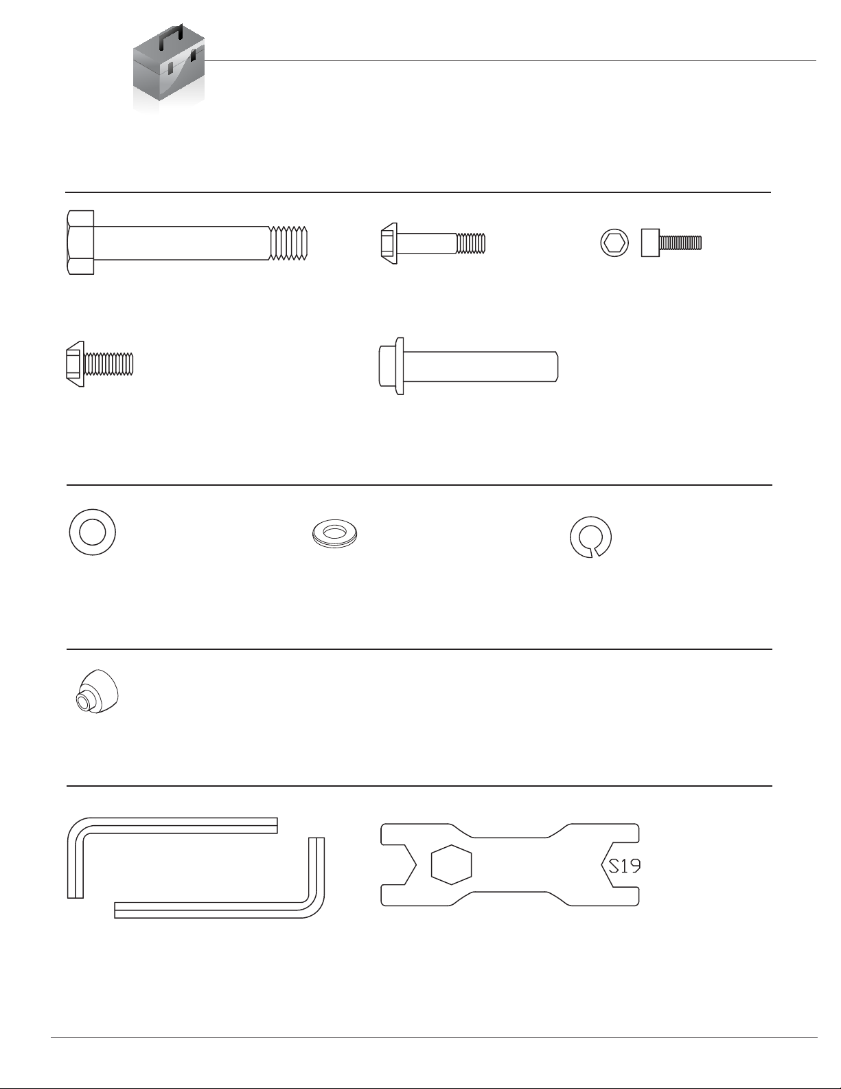
Hardware & Tool List
The following hardware is used to assemble your unit. Please take a moment to familiarize yourself with these items.
PLEASE NOTE: some of these parts may have already been pre-assembled on your unit.
BRW7200/7900 BODY ROWER Page 2
#2. Bolt (M12 ×160 mm)
[4 Pieces]
#7. Bolt (M8×50 mm)
[2 Pieces]
#19. Bolt (M6×15 mm)
[1 Piece]
#20. Bolt (M8×20 mm)
[2 Pieces]
#22. Axle (Φ10.9×80mm)
[1 Piece]
#8. Washer (M8)
[4 Pieces]
#24. Washer (M6)
[1 Piece]
#33 Spanner S6
#34 Spanner S5 #35 Wrench S17-S19
#36. Spring Washer (M8)
[2 Pieces]
Bolt
Washer
Tool
Block
#23. Block
[ PieceV]

Parts Listing
The following parts list describes all of the parts illustrated on the
exploded diagram on the following page. Please note, most of
these parts are already pre-assembled on your unit.
BRW7200/7900 BODY ROWER Page 3
# Description
1 Monitor
2 Bolt (M12 ×160 mm)
3L/R Pedal
4 Lock Bolt (M16×27 mm)
5 Wire
6L/R Oval End Cap
7 Bolt (M8×50 mm)
8 Washer (M8)
9 Front Stabilizer
10 Washer (M4.2)
11 Screw (ST4.2×16 mm)
12 Rubber End Cap (Ф38 mm)
13 Bolt (M12×139 mm)
14 Bushing (Φ50×Φ12×23 mm)
15 Aluminum Track Joint
16 Washer (M12)
17 Nylon Nut (M12)
18 Seat Cushion
19 Bolt (M6×15 mm)
20 Bolt (M8×20 mm)
21 Aluminum Track
22 Axle (Φ10.9×80mm)
23 Block
24 Washer (M6)
25 Sensor Cable
26 AC Adapter
27 Main Frame
28 Handlebar Foam
29 Round Inner Cap
30 Handlebar
31 Strap
32 protective Packing Material
33 Spanner (S6)
34 Spanner (S5)
35 Wrench (S17-S19)
36 Spring Washer (M8)
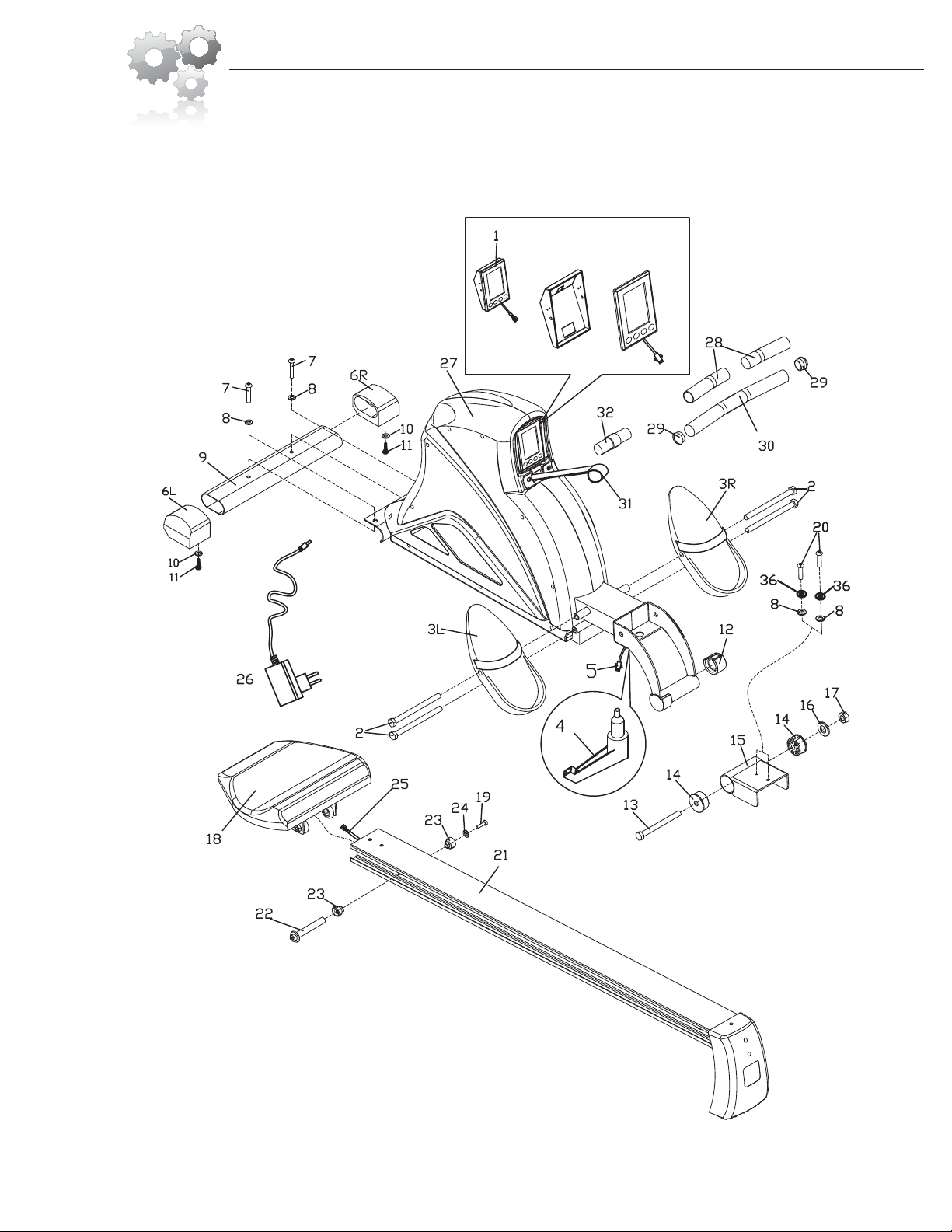
Exploded Diagram
BRW7200/7900 BODY ROWER
Page 4
The following diagram is provided to help you familiarize yourself with the parts and hardware
that will be used during the assembly process. Please note that not all of the parts and hardware
you see here will be used while you are assembling the machine because some of these items
are already pre-installed. Please continue to the next page to begin the assembly process and
use this page only as a reference guide for parts and hardware.

Assembly Instructions
Assembly Step 1
Attach the Front Stabilizer (#9) to the Main Frame (#27)
with the wheels of the Front Stabilizer (#9) facing the front
of the unit and align the holes on the Main Frame (#27) to
the Front Stabilizer (#9). Secure them together using two
Washers (#8) and two Bolts (#7)."
Hardware and Tool Required
#7. Bolt (M8×50 mm)
[2 Pieces]
#8. Washer (M8)
[2 Pieces]
#33 Spanner S6
Bolt
Washer
Tool
BRW7200/7900 BODY ROWER Page 5
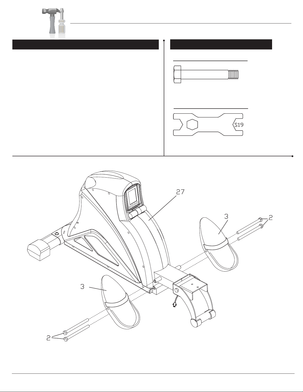
Assembly Instructions
Assembly Step 2 Hardware and Tool Required
Secure a Bolt (#2) to the lower hole on the left side
of the Main Frame (#27). Insert a Bolt (#2) through the
left Pedal (#3L) and secure it to the top hole on the left
side of the Main Frame (#27) as indicated in the
illustration below.
Repeat this process on the other side.
L
R
#2. Bolt (M12 ×160 mm)
[4 Pieces]
#35 Wrench S17-S19
Bolt
Tool
BRW7200/7900 BODY ROWER Page 6
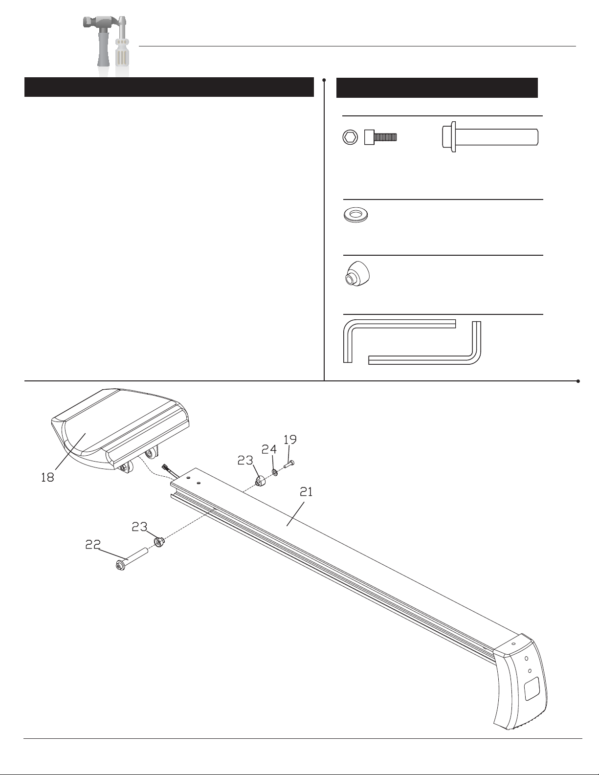
Assembly Instructions
Assembly Step 3
Slide the Seat Cushion (#18) in to the Aluminum Track
(#21) as illustrated in the diagram below. Once the Seat
Cushion (#18) is in the Aluminum Track (#21), slide the
Axle (#22) in to the Block (#23) and through the Aluminum
Track (#21). Secure it by inserting a Bolt (#19) through a
Washer (#24), followed by a Block (#23) and in to the Axle
(#22).
#19. Bolt (M6×15 mm)
[1 Piece]
#22. Axle (Φ10.9×80mm)
[1 Piece]
#24. Washer (M6)
[1 Piece]
#33 Spanner S6
#34 Spanner S5
Bolt
Washer
Tool
Block
#23. Block
[ Pieces]
Hardware and Tool Required
BRW7200/7900 BODY ROWER Page 7
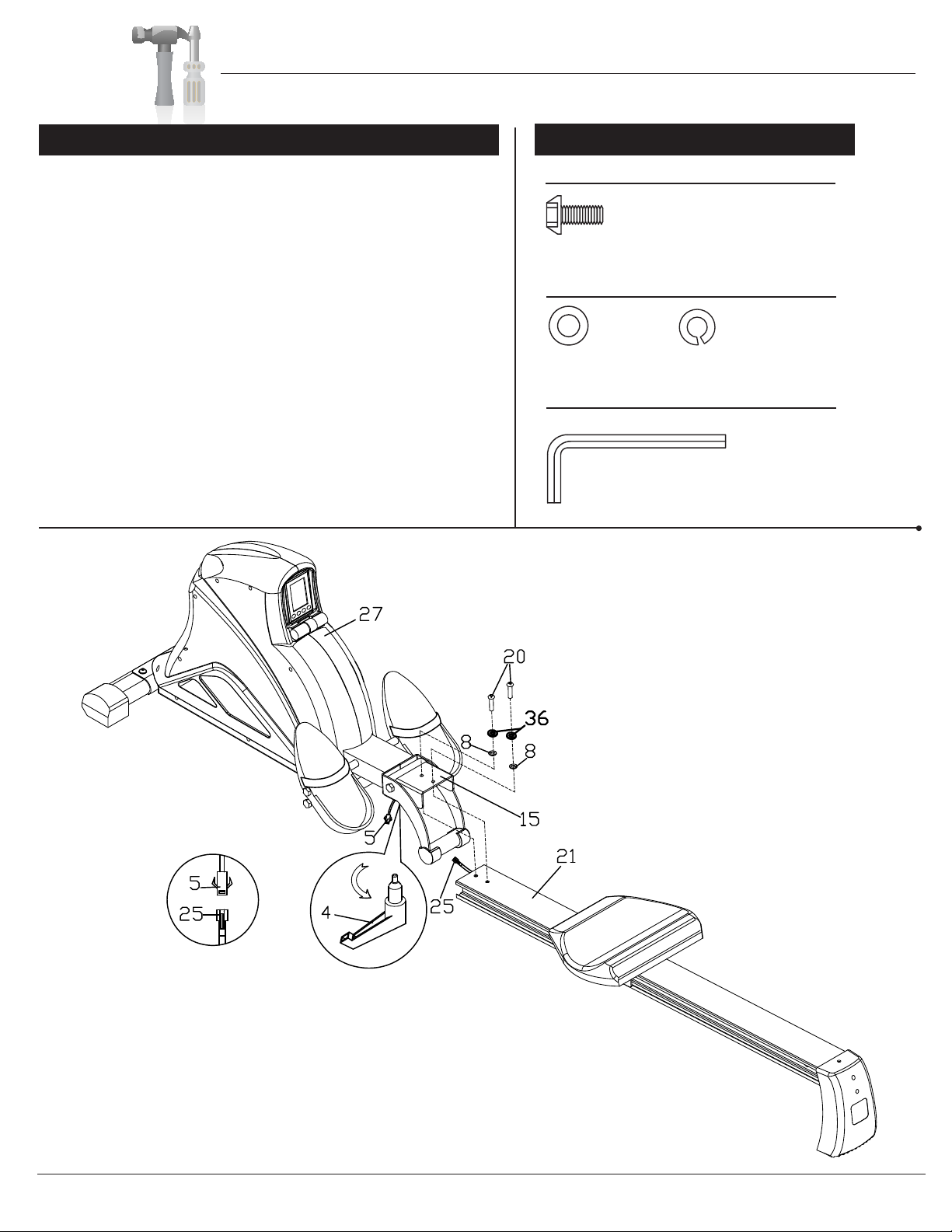
Assembly Instructions
Assembly Step 4
Remove the Lock Bolt (#4) which were pre-assembled on
the Main Frame (#27) and set them aside as they will be
used in a later process.
With the help of an assistant, attach the Aluminum Track
(#21) to the Aluminum Track Joint (#15) and secure them
together using two Washers (#8), two Spring Washers
(#36) and two Bolts (#20). Once the Aluminum Track (#21)
is secured to the Main Frame (#27), connect the Sensor
Cable (#25) from the Aluminum Track (#21) to the Wire
(#5) on the Main Frame (#27). Screw the Lock Bolt (#4) in
to the Main Frame (#27) and turn in the direction indicated
on the illustration to lock the Lock Bolt (#4) in to the Main
Frame (#27).
*NOTE: When securing the Lock Bolt (#4), slightly lift the
Aluminum Track (#21) while turning the Lock Bolt (#4)
Handle. This would allow the Lock Bolt (#4) to easily go
into place.
Hardware and Tool Required
BRW7200/7900 BODY ROWER Page 8
#20. Bolt (M8×20 mm)
[2 Pieces]
#8. Washer (M8)
[2 Pieces]
#33 Spanner S6
Bolt
Washer
Tool
#36. Spring Washer (M8)
[2 Pieces]
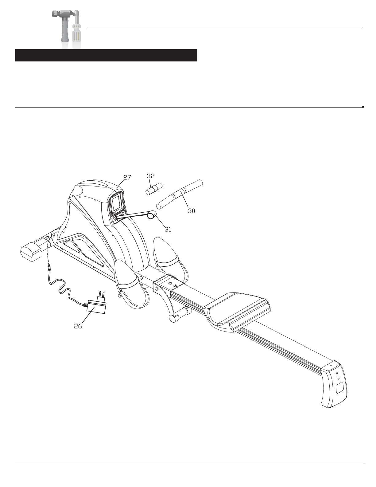
Assembly Instructions
Assembly Step 5
Carefully pull out the Strap (#31) and hold on the Strap (#31) while removing the Protective Packing Material
(#32) without letting go of the Strap (#31). Insert the Handlebar (#30) through the Strap (#31) and align the
Handlebar (#30) to the center of the strap.
Plug in the AC Adapter (#26) male plug into the female socket located at the rear end of the unit.
BRW7200/7900 BODY ROWER Page 9

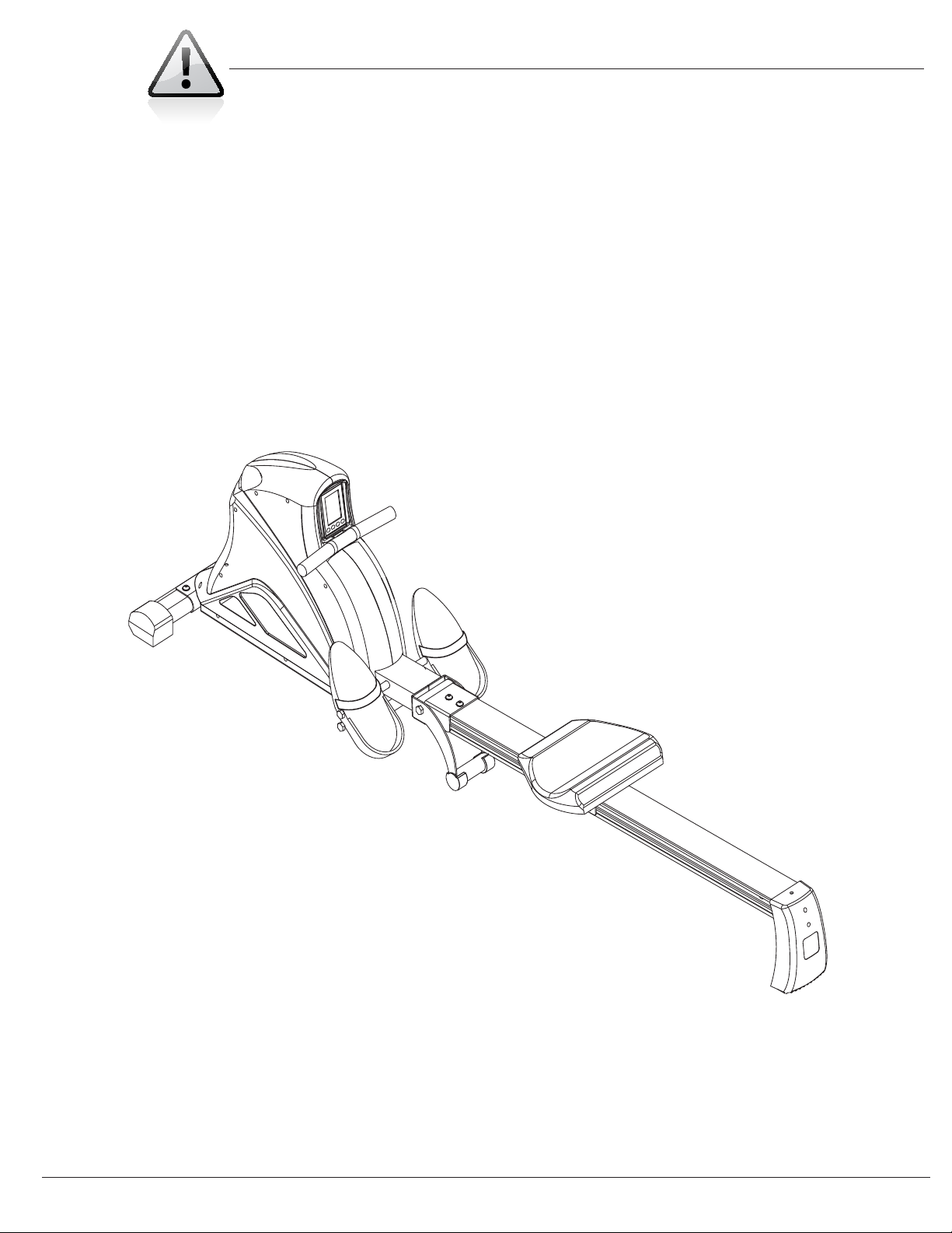
Assembly Instructions
Assembly Step 6
The Monitor (#1) can be tilted upwards slightly when you push the top of the Monitor (#1).
BRW7200/7900 BODY ROWER Page 10
Safety Instructions
• Make sure all bolts are tightened.
• Check for loose parts and components
• Check to see if there are any tears or bends in the welding or metal.
• Be sure that all adjustment locking devices and safety devices are
properly engaged prior to use!
BRW7200/7900 BODY ROWER Page 11
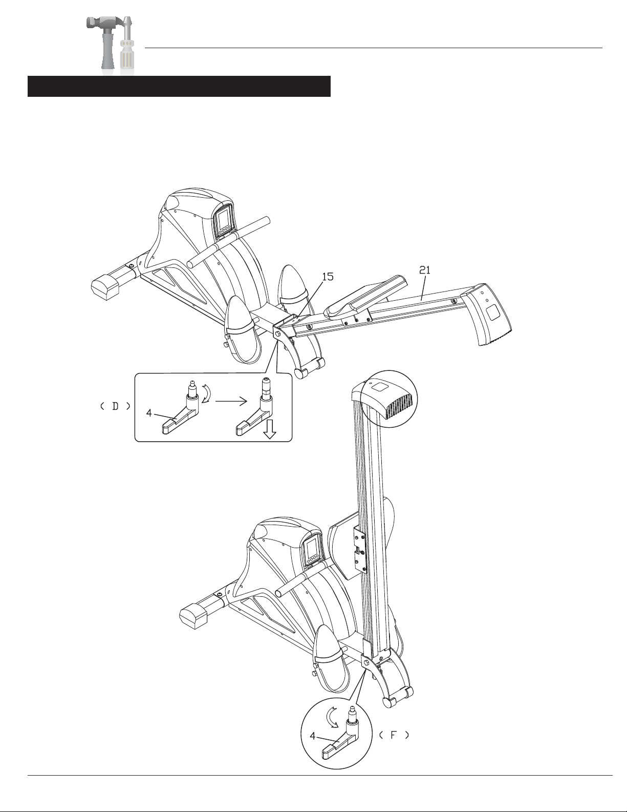
Usage Guidelines
The Aluminum Track (#21) can be folded upwards to save space. In order to free the Aluminum Track (#21)
turn the Lock Bolt (#4) in the direction indicated in illustration (D) and pull downwards to free the Lock Bolt (#4).
While pulling down on the Lock Bolt (#4), you can now carefully lift the Aluminum Track (#21) up until the
Lock Bolt (#4) goes into place. Once the Lock Bolt (#4) is in place turn it in the direction indicated in illustration
(F) to secure the Lock Bolt (#4) in place.
Foldable
BRW7200/7900 BODY ROWER Page 12
*NOTE: When securing the Lock Bolt (#4),
slightly lift the Aluminum Track (#21) while
turning the Lock Bolt (#4) Handle. This would
allow the Lock Bolt (#4) to easily go into place.
Computer Operation
BRW7200/7900 BODY ROWER Page 13
Function:
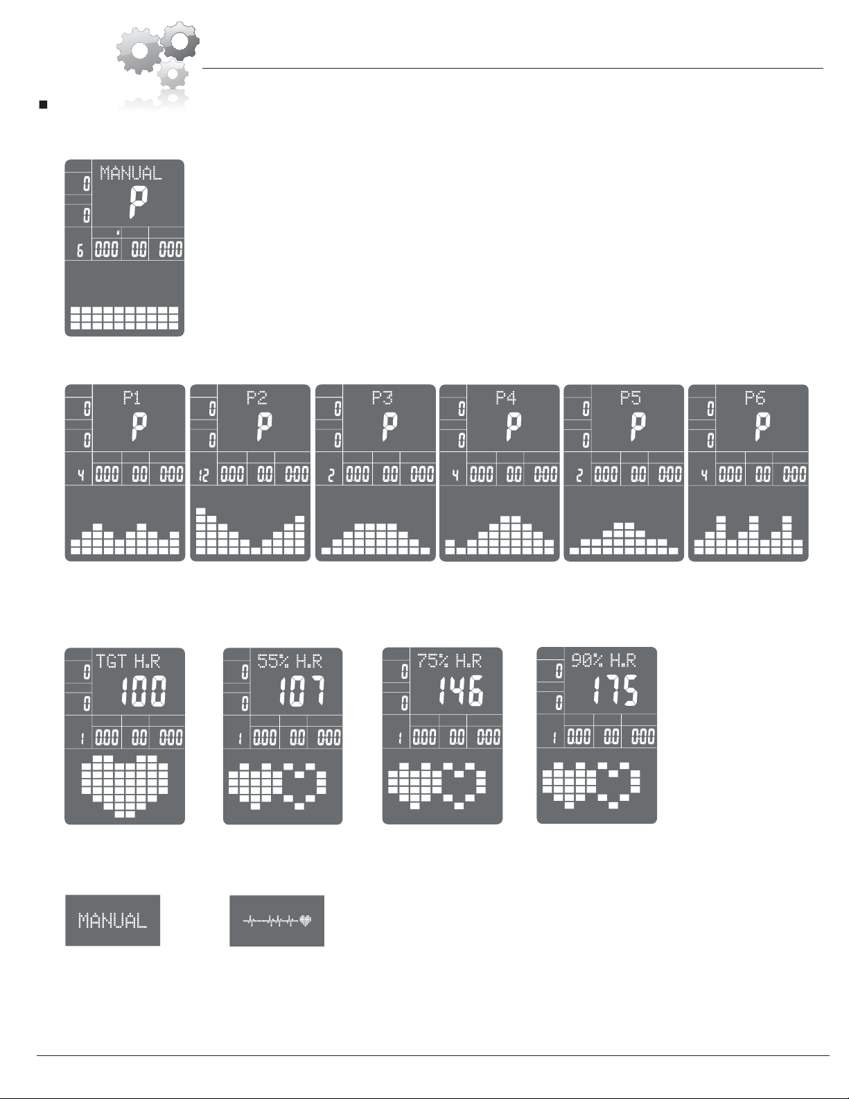
1.Program: 11 programs as following
A: 1 Manual Program (See fig 1)
B: 6 Preset Program Profile: (See fig 2~fig 7 )
fig 1
fig 2 fig 3 fig 4
STOP
LEVEL
TIME
CAL
SPM
STROKES
DISTANCE
STOP
LEVEL
TIME
SPM
STROKES
DISTANCE M
CAL
LEVEL
STOP
TIME
SPM
STROKES
DISTANCE M
CAL
TIME
SPM
STROKES
DISTANCE M
CAL
STOP
LEVEL
P1: ROLLING P2:VALLEY P3: FATBURN P4:RAMP P5:MOUNTAIN P6: INTERVAL
fig 5 fig 7
fig 6
STOP
LEVEL
TIME
CAL
SPM
STROKES
DISTANCE M
STOP
LEVEL
TIME
CAL
SPM
STROKES
DISTANCE M
STOP
LEVEL
TIME
CAL
SPM
STROKES
DISTANCE M
STOP
LEVEL
TIME
CAL
SPM
STROKES
DISTANCE M
STOP
LEVEL
TIME
CAL
SPM
STROKES
DISTANCE M
fig 8 fig 10
fig 9 fig 11
2. Dot matrix display showing your current status. (See fig 12)
3. Simulative ECG measuring the heart rate (See fig 13)
4. Display rowing speed(SPM), STROKES, TIME, DIST., CAL., PULSE, LEVEL at the same time.
5. If set TIME and DIST, the computer will calculate the average rowing speed and SPM will flash. If the current rowing speed is higher than average speed, "+"
will flash. If the current speed is the same to average, "0" will flash. If the current speed is lower than average, "-"will flash.
6. The computer will turn off automatically if there is no operation, rowing signal and pulse signal over 4 minutes. Meanwhile, it will store your current exercise
data and turn the loading resistance to the minimum. Once you press any button or in motion, the computer will turn on automatically.
fig 12
STOP
LEVEL
TIME
CAL
SPM
STROKES
DISTANCE M
C: 4 Heart Rate Control Program:(See fig 8 ~ fig 11)
TARGET H.R and 55%H.R, 75%H.R, 90%H.R
STOP
LEVEL
TIME
CAL
SPM
STROKES
DISTANCE M
fig 13

Computer Operation
BRW7200/7900 BODY ROWER
Page 14
Buttons:
1.MODE
In "stop" mode(display STOP), press MODE button to enter into program selection and setting value which flash in related window.
A: When you choose the program, press MODE to confirm the one you like.
B: When in setting, press MODE to confirm the value that you would like to preset.
During any mode, hold down this button for 2 seconds to totally reset the computer.
2.UP:
In stop mode and the dot matrix character flash, press this button to select the program up. If the related window value flash, press this button to increase the
value.
During the start mode(display START), press this button to increase the training resistance.
3.DOWN:
In stop mode and the dot matrix character flash, press this button to select the program down. If the related window value flash, press this button to decrease
the value.
During the start mode(display START), press this button to decrease the training resistance.
4.RECOVERY:
First test your current heart rate and show your heart rate value, press this button to enter into pulse recovery testing.
When you are in pulse recovery mode, press this button to exit.
Operation
1.Turn on the computer
Plug in one end of the adaptor to the AC electrical source and connect the other end to the computer.
The computer will beep and enter into initial mode.(See fig 14)
2.Program select and value setting(When display "STOP")
Manual Program and Preset Program P1~P6
A.Press UP, DOWN button to select the program that you like.(See fig 15)
B.Press MODE button to confirm the selected program and enter time setting window.
C.The time will flash, and then press UP, DOWN button to set up your desired time. Press MODE
to confirm the value. (See fig 16)
D.The distance will flash, and then press UP, DOWN to set up the desired distance value. Press MODE to confirm the value. (See fig 17) If already set the time,
"SPM" in left top LCD will flash and display the target average speed.
E.The calories will flash, and then press UP, DOWN to set up the desired calories to be consumed. Press MODE to confirm the value. (See fig 18)
F. When start rowing, the display "STOP" will switch to "START".(See fig. 19)
fig14
fig 16
fig 15
fig17
fig 19
fig 18
START STOP
LEVEL
TIME
CAL
SPM
STROKES
DISTANCE M
PULSE
YEAR
cm in
Kg lb
STOP
LEVEL
TIME
SPM
STROKES
DISTANCE M
CAL
STOP
LEVEL
TIME
SPM
STROKES
DISTANCE M
CAL
STOP
LEVEL
TIME
CAL
SPM
STROKES
DISTANCE M
STOP
LEVEL
TIME
CAL
SPM
STROKES
DISTANCE M
LEVEL
TIME
CAL
SPM
STROKES
DISTANCE M
START
HEART RATE CONTROL PROGRAM: TARGET HEART RATE
The user can set any target heart rate to do the exercise.
A.Press UP, DOWN to select TARGET HEART RATE program.
Computer Operation
BRW7200/7900 BODY ROWER Page 15
F.If the computer does not detect your current heart rate first, pressing RECOVERY will not enter into pulse recovery test. During the pulse recovery test,
press RECOVERY to exit the test and return to the stop status.
B.Press MODE to confirm your choice and enter time setting window.
C.The time display will flash, and then press UP, DOWN to set the desired time to do the exercise. Press MODE to confirm the value.
D.The distance will flash, and then press UP, DOWN to set up the desired distance value. Press MODE to confirm the value. If already set the time, "SPM" will
flash and display the target average rowing speed.
E.The calories will flash, and then press UP, DOWN to set up the desired calories to be consumed. Press MODE to confirm the value.
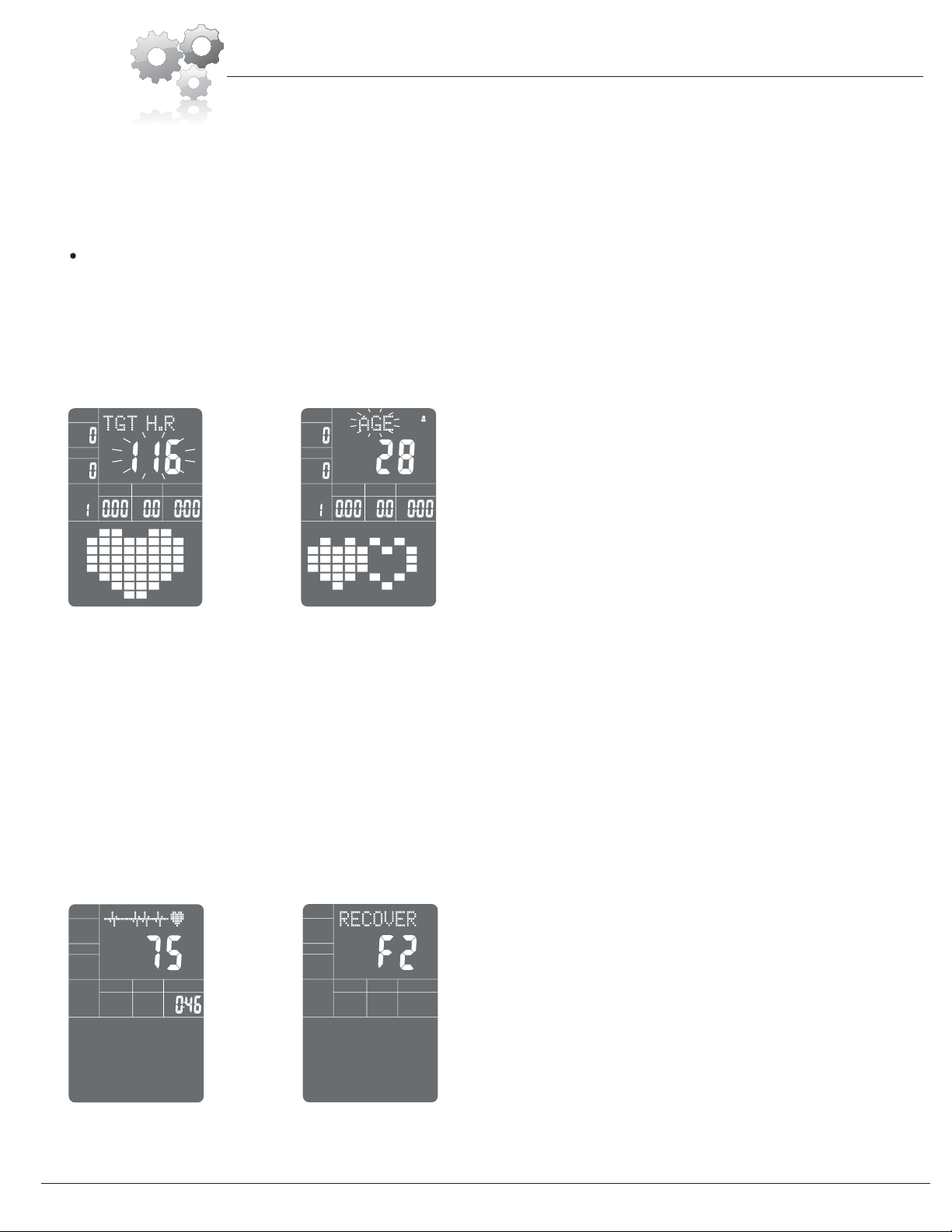
F.The target heart rate will flash, and then press UP, DOWN to set up your target heart rate. Press MODE to confirm the value.(See fig 20)
HEART RATE CONTROL PROGRAM: 55%H.R, 75% H.R and 90% H.R (When display "STOP")
The maximum heart rate depends on different age and this program will ensure you do the healthy exercise within maximum heart rate.
A.Press UP , DOWN to choose the heart rate control program
B.Press MODE to confirm the heart rate control program, and enter into time setting window.
C.The time will flash, and then press UP, DOWN button to set up the desired time. Press MODE to confirm the value.
D.The distance will flash, and then press UP, DOWN to set up the desired distance value. Press MODE to confirm the value. If already set the time, "SPM"
will flash and display the target average rowing speed.
E.The calories will flash, and then press UP, DOWN to set up the desired calories to be consumed. Press MODE to confirm the value.
F.The age will flash, and then press UP, DOWN to set the user's age. Press MODE to confirm the value. (See fig 21)
G.When the target heart rate control program flash, the computer will display the user's target heart rate according to user's age.
H.When start rowing, the display "STOP" will switch to "START".
3.Pulse Recovery Test
The pulse recovery test is to compare your heart rate before and after exercise. It is target to determine
your heart strength via the measuring. Please do the test as below:
A.Wear the chest strap measure heart rate, the computer will display your current pulse value.
B.Press RECOVERY to enter the pulse recovery test and the computer program will enter the stop
status.(See fig22)
C.Keep pulse detecting.
D.Time will count down from 60 seconds to 0 second.
E.When time reaches 0, the test result (F1-F6) appears on the display.
F1=Excellent F2=Good F3=Fair F4=below average F5= No Good F6= Poor(See fig 23)
TIME
fig 22 fig 23
NOTE: During exercise, the user's heart rate value depends on resistance level and speed. The heart rate control program is to ensure your heart rate within the
preset value. When the computer detect your current heart rate is higher than preset, it will decrease the resistance level automatically or you may slow down
exercise. If your current heart rate is lower than preset, it will increase resistance and you may speed up.
YEAR
STOP
LEVEL
TIME
CAL
SPM
STROKES
DISTANCE M
STOP
LEVEL
TIME
CAL
SPM
STROKES
DISTANCE M
fig 20 fig 21

Computer Operation
BRW7200/7900 BODY ROWER Page 16
4.Pulse Measurement
Wear the chest strap and measure your heart rate, the computer will show your current heart beat rate in beats per minute (BPM) on the LCD after 3~4 seconds.
During the measurement, heart icon will flash with simulative ECG showing.
Remark: During the process of pulse measurement, because of the contact jamming, the measurement value may not be stable when start, then it will return to
normal level. The measurement value cannot be regarded as the basis of medical treatment.
Specifications
SPM: Showing the current rowing frequency per minute. Range : 0~999.
STROKES: Showing the current rowing count . Range:0~999.
TIME: The accumulative exercise time, range : 0:00~99:59.
Preset time range is 5:00~99:00. The computer will start to count down from preset time to 0:00 with average time for each resistance level. When it reaches to
zero, the program will stop and computer alarm. If you do not preset the time, it will run with one minute decrement each resistance level.
DIST: The rowing accumulative distance. Range : 0.00~9.99~99.9 MILE
the preset distance range :0.50~9.50~99.5 When the distance reaches 0, the program will stop and the computer will alarm.
CALORIE: The exercise accumulative calories burnt. Range : 0.0~99.9~999
the preset calories range :10.0~90.0~990. When the calorie reaches 0, the program will stop and the computer will alarm.
PULSE: Showing the exercise heart rate value. Range: 60~220BPM(beat per minute)
RESISTANCE LEVEL: Showing resistance level. Range:1~16 with 8 segments display.
NOTE: 1. TIME and DIST can be set at the same time. But once set TIME and DIST, the user can not set CALORIE.
2. The user cannot set TIME and CALORIE, or DIST and CALORIE at the same time. That is to say, if set time, but not set distance, the proceed to set
calorie, the time will reset to zero. If set distance, but not set time, then proceed to set calorie, the distance will reset to zero.
3. If preset the TIME or DIST or CALORIE, the computer will display "STOP"and alarm when any of preset value reach zero. But keep rowing, the "STOP"
will switch to "START" and the window of zero will count up.
4. After preset TIME and DIST, the computer will calculate and display the target average speed automalically. Even the preset time or distance reach zero,
the computer will keep displaying target average speed and only when change the rowing program or reset, the target speed can be cleared.
BREAKDOWN DISPLAY
1.When the computer displays ERROR1, please check if the motor is good and if the motor wires
connect well.
ADAPTOR
INPUT: AC (The voltage depends on different country)
OUTPUT: 8VDC 500mA

Transmitter Belt Operation
BRW7200/7900 BODY ROWER Page 17
Introduction
Thetransmitterchestbeltwilldetectheartratesignalandwirelesslytransferthesignalstothereceiving
terminallikepulseawatch,exercisecomputer,etc,wherewilldisplaytheheartratereadout.This
measurementwillbeaccurate.Itapplieslowfrequencyfortransmissionandenvironmental‐conserved
materials.Thewater‐resistdesignwillprotectitfromsweatduringexercise.
Feature
1. Thetransmissionfrequencyis5.3KHZanditiscompatiblewithPOLAR.
2. Thetransmissiondistanceis85cm,maximum100cm.
3. Battery:1pcCR2032.Thebatterywilllastfor9monthifuse1hourperday.
Component
A. Sensor
B. ConnectionBelt
C. Transmitter
D. BatteryHousing
E. ElasticBelt
F. Breach
Howtowearthetransmitterbelt
WiththeF(Breach)downbelow,insertoneendofE(ElasticBelt)intotheholeofB(ConnectionBelt),then
turnaroundtheElasticBeltendtorightfittheholeandpresstheconnectionpart.Wearthetransmitter
beltwithC(Transmitter)closelytouchyourchest.TheninserttheotherendofE(ElasticBelt)intothe
otherholeofB(ConnectionBelt).AdjusttheElasticBelttotightlywearthebelt.PleasenotethattheA
position(Sensor)shouldcloselytouchtherightandleftventricleskin.
Remark:Youmaycheckasfollowingtoseeifyouwearthetransmitterbeltproperly:
1. ThebatteryhousingisoppositetoabovepositionG.
2. Thetransmitterrunsparalleltothefloor.
3. Bothsensorcloselytouchtheskinoftherightandleftventricle.
BatteryReplace
Ifthetransmissioncouldnotreach85cm,pleasereplacenewCR2032Battery.Usethescrewdrivertoloose
screwsandopenthebatterycover.TakeofftheoldbatteryandreplacewithnewCR2032.Pleasenotethat
the“+”sideisupturnedandinsertthebatteryasfollowingshownarrow.Afterfixthebatterywell,close
thebatterycoverandscrewdown.
Remark:
1. Thetransmitterthebeltmaynotaccuratelytestthepulseifthechestskinistoodry.Thenyoumay
moisturetheA(Sensor)andtestthepulseagain.
2. Thesensormaynotdetecttheheartratesignalifthechesthairistoodense.Pleasewearthechestbelt
awayfromdensehairifpossible.

Thanks for choosing
BRW 7200/7900
Store Location:
Version: 02-22-2011
Hupa International
hupa.net

Hupa international • 21717 Ferrero Parkway, Walnut, CA 91789 • Telephone: (888) 266 - 6789 • Email: info@hupa.net
This manual suits for next models
1
Table of contents
Other Body Champ Home Gym manuals


