Body Champ lb 2600 User manual


General Information
Assembling Tools
• Ruler with both metric and English measurement
• 2 x Adjustable Wrench
Warranty
Body Flex Sports warrants your product for
a period of 1 year for the frame and 90 days
on all parts if the item is used for the intended
purpose, properly maintained and not used
commercially. Any alterations or incorrect
assembly of the product will void this warranty.
Proof of purchase must be presented for any
warranty validation (no exceptions). This
warranty applies to the original purchaser only
and is not transferable.
This warranty does not cover abuse or defects
caused during use, storage or assembly.
During the warranty period, Body Flex Sports
reserves the right to:
a). provide replacement parts to the
purchaser in an effort to repair the item.
b). repair the product returned to our
warehouse (at the purchaser’s cost).
c). replace the product if neither of the two
previously mentioned actions effect repair.
This warranty does not cover normal wear and
tear on upholstery.
Questions
If you have any questions concerning the
assembly of your item or if any parts are
missing, please DO NOT RETURN THE
ITEM TO THE STORE OR CONTACT THE
RETAILER. Our dedicated customer service
staff can help you with any questions you may
have regarding the assembly of this unit and
can also mail you replacement parts.
Customer Support
Customer Support is open 9:00 a.m. to 5:00
p.m. (Pacic Time) Monday through Friday.
Please contact us by any of the following
means.
Body Flex Sports, Inc.
21717 Ferrero Parkway, Walnut, CA 91789
Telephone: (888) 266 - 6789
Fax: (909) 598 - 6707
Email: info@bodyexsports.com
Safety
Before you undertake any exercise program,
please be sure to consult with your doctor.
Frequent strenuous exercise should be
approved by your doctor and proper use
of your product is essential. Please read
this manual carefully before commencing
the assembly of your product or starting to
exercise.
• Please keep all children away from this item
when in use. Do not allow children to climb or
play on them when they are not in use.
• Supervise teenagers while they use this unit.
• For your own safety, always ensure that there
is at least 3 feet of free space in all directions
around your product while you are exercising.
• Regularly check to see that all nuts, bolts and
ttings are securely tightened. Periodically
check all moving parts for obvious signs of
wear or damage.
• Clean only with a damp cloth, do not use
solvent cleaners. If you are in any doubt, do
not use your product; contact CUSTOMER
SUPPORT.
• Before use, always ensure that your product
is positioned on a solid, at surface. If
necessary, use a rubber mat underneath to
reduce the possibility of slipping.
• Always wear appropriate clothing and
footwear such as training shoes when
exercising. Do not wear loose clothing that
could become caught in moving parts during
exercise.
• Do not use this unit if it is not functioning
properly or if it is not fully assembled.
• Do not use this unit for commercial purposes.
Storage and Use
Your product is intended for use in clean
dry conditions. You should avoid storage in
excessively cold or damp places as this may
lead to corrosion and other related problems.
Weight Limit
The maximum weight capacity for the Press Arms
is 120 lbs per each Press Arm (Total 240 lbs) and
60 lbs for the Leg Developer.
Page 2

Page
BEFORE ASSEMBLY
Nylon Lock Safety Nuts
A. It is only necessary to tighten the bolts and nuts to “finger tight” during the
assembly process. This will make it easier to complete certain steps by
allowing more tolerance for all the parts to fit properly.
B. Do not tighten all the nuts onto the bolts securely until after you have
completed assembly of your product.
C. Use wrenches, pliers, or ratchet and sockets to tighten the bolts and nuts.
D. The Nylon Nut should thread onto the Hex Bolt until the end of the Hex Bolt
has broken through the Nylon insert inside the Nut.
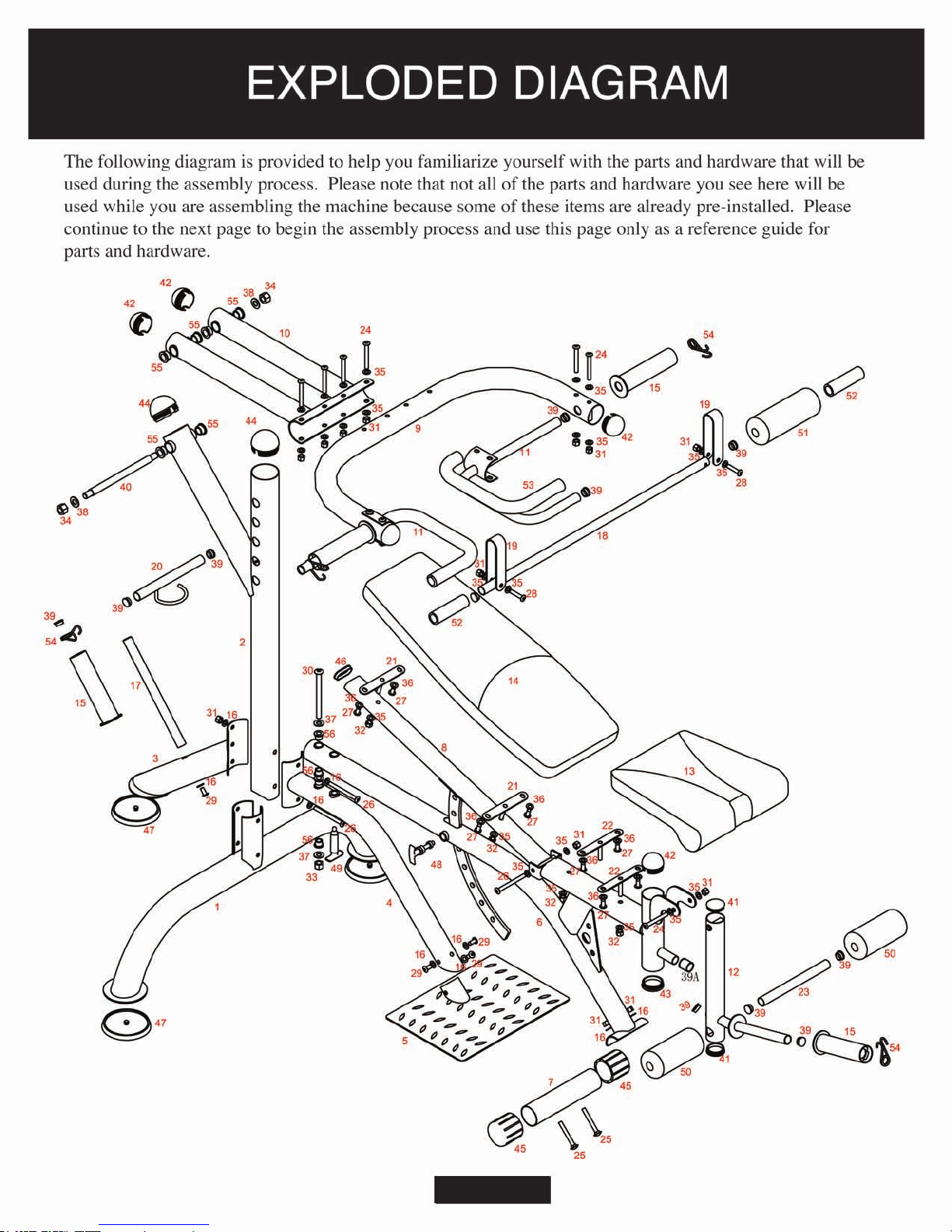
Take a few moments to familiarize yourself with the specific parts hardware
included with your product. Make sure all the parts and hardware are included in
the cartons and examine them for any damage that may have occurred in
transport. Some parts may be pre-assembled and pre-installed
Wiring and Loose Components
A. Check all wiring for rips and tears
B. Check the frame for any damage
C. Make sure all the hardware is included
Take a few minutes to familiarize yourself with the parts and hardware included with your product.
IMPORTANT PLEASE NOTE: MANY OF THE PARTS AND HARDWARE LISTED ON THE PARTS
LIST ARE ALREADY PRE-ASSEMBLED OR INSTALLED ON THE MACHINE.
Required Tools & Safety Procedures
A. You will need two adjustable
wrenches and allen wrenches.
B. We strongly recommend that you
assemble this machine with the help
of one or more people to ensure
your safety.

HARDWARE LIST
IMPORTANT PLEASE NOTE: The hardware listed below is a list of ALL the hardware
used on your weight bench. Some of this hardware is already pre installed on your
product. Do not be alarmed if you are missing any of these parts.
Spanner [2 pieces]........................
(#58) Wrench [1 piece]
(#57) Allen Key
[1 piece]
(#30) Button Bolt (1/2'' x 6'')
(#26) Button Bolt (3/8'' x 4-1/8'') [3 pieces]
(#25) Carriage Bolt (3/8'' x 3'') [2 pieces]
(#24) Button Bolt (3/8'' x 3-1/4'') [9 pieces]
(#28) Button Bolt (3/8'' x 1-7/8'') [2 pieces]
(#29) Button Bolt (3/8" x 3/4'') [4 pieces]
(#27) Button Bolt (5/16" x 5/8") [8 pieces]
[2 pieces]
(#34) Nylon Lock Nut (5/8" x 19t) [2 pieces]
(#33) Nylon Lock Nut (1/2" x 15t) [1 piece]
(#31) Nylon Lock Nut (3/8" x 11t) [15 pieces]
(#32) Nylon Lock Nut (3/8" x 8t) [4 pieces]
(#38) Washer (5/8") [2 pieces]
(#37) Washer (1/2") [2 pieces]
(#35) Washer (3/8") [28 pieces]
[8 pieces]
[9 pieces]
(#36) Washer (5/16")
(#16) Curved Washer (3/8")
Page 4

PARTS LIST
Part
#
Description
Qty.
Part
#
Description
Qty.
1BackBaseFrame
1
31
Nylon Lock Nut (3/8" x 11t)
15
2
Back Upright
1
32
Nylon Lock Nut (3/8" x 8t)
4
3
Stabilizer Tube
1
33
Nylon Lock Nut (1/2" x 15t)
1
4
Front Tube
1
34
Nylon Lock Nut (5/8" x 19t)
2
5
Foot Plate
1
35
Washer (3/8")
28
6MainFrame
1
36
Washer (5/16")
8
7
Base Tube
1
37
Washer (1/2")
2
8
Backrest Tube
1
38
Washer (5/8")
2
9
Press Arm
1
39
Round Inner Plug( Φ25)
13
10
Press Frame
1
39AEndCap(Φ25)
1
11
Handle Bar
2
40
Shaft
1
12
Leg Curl Tube
1
41
Round Inner Plug( Φ50)
2
13
Seat Cushion
1
42
Round Inner Plug( Φ60)
5
14BackrestCushion143RoundInnerPlug(Φ60)1
15OlympicAdapter444RoundInnerPlug(Φ70)2
16CurvedWasher945EndCap(Φ60)2
17StorageBar146InnerPlug(30x60x1.5mm)1
18SquatBar147EndCap3
19Bracket248LockPin1
20AdjustmentBar149KnobBolt1
21BackrestPlate250FoamRoller2
22SeatPlate251FoamRoller1
23RollerTube152HandleFoam2
24ButtonBolt(3/8"x3-1/4")953HandleFoam2
25CarriageBolt(3/8"x3")254QuickClip4
26ButtonBolt(3/8"x4-1/8")355Bushing6
27ButtonBolt(5/16"x5/8")856Bushing4
28ButtonBolt(3/8"x1-7/8")257AllenKey2
29ButtonBolt(3/8"x3/4")458Wrench1
30ButtonBolt(1/2"x6")159Owner'sManual1
The quantity may be different from the parts list because some parts are pre-assembled on the unit .
Page 5
Page 6

UPRIGHT ASSEMBLY STEP 1
OLYMPIC ADAPTER
If you intend to use Olympic plates,
slide the Olympic Adapter (#15)
over the standard plate post and
secure with one Spring Clip (#54)
A
D
C
E
B
A. Insert Back Upright (#2) into the upper bracket of the
Back Base Frame (#1) and align the two pairs of holes.
B. Connect the Front Tube (#4) and Stabilizer Tube (#3)
to the top bracket of the Back Base Frame (#1)
C. Tighten the nut and bolts firmly using an Allen Key (#57)
and a Wrench (#58).
D. Slide the Front Tube (#4) into the opening on the Foot
Plate (#5). Align the holes on the Foot Plate (#5) to the
holes on the Front Tube (#4). Secure and tighten the tube
with three Curved Washes (#16) and three Button Bolts
(#29) as illustrated below.
E. Attach the Storage Bar (#17) to the Stabilizer Tube (#3)
using a Button Bolt (#29) and a Curved Washer (#16).
Slide the Olympic Adapter (#15) onto the Storage Bar
(#17) and secure it with a Quick Clip (#54).
With the help of an assistant, secure the bottom hole of the
Back Base Frame (#1), Back Upright (#2), Stabilizer Tube
(#3), and Front Tube (#4) with a Curved Washer (#16) and
a Button Bolt (#26) directly into the Stabilizer Tube (#03).
Then secure the top hole with a Button Bolt (#26), two
Curved Washers (#16) and a Nylon Lock Nut (#31).
.
Page 7
(#26) Button Bolt (3/8'' x 4-1/8'') [2 pieces]
(#29) Button Bolt (3/8" x 3/4'') [4 pieces]
(#31) Nylon Lock Nut (3/8" x 11t) [1 pieces]
[7 pieces]
(#16) Curved Washer (3/8")
Hardware Required for Step 1
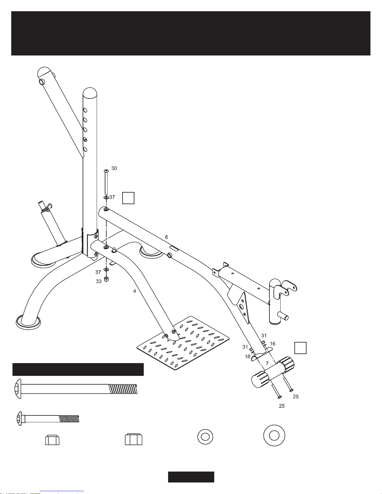
MAIN FRAME ASSEMBLY STEP 2
Page 8
A
B
A. Attach Base Tube (#7) onto the Main Frame (#6) and
secure the two parts with two Carriage Bolts (#25), two
Curved Washers (#16) and two Nylon Lock Nuts (#31).
Tighten the nuts and bolts using a Wrench (#58) and an
Allen Key (#57).
B. Place the Main Frame (#6) assembly onto the Front Tube
(#4) and align the holes. Secure the Front Tube (#4) and
Main Frame (#6) with one Button Bolt (#30) and two
Washers (#37) then tighten the Button Bolt (#30) with one
Nylon Lock Nut (#33).
NOTE: The Deluxe Leverage Bench System allows you to switch
from the bench position to the squat position during your exercise
routine (after the assembly process is complete). To switch to the
squat position, simply unscrew the Knob Bolt (#49) and swivel
the end of the Main Frame (#6) either to the left or right (until
it is out of way) to use the squat feature.
Hardware Required for Step 2
[1 piece]
(#30) Button Bolt (1/2'' x 6'')
(#25) Carriage Bolt (3/8'' x 3'') [2 pieces]
(#33) Nylon Lock Nut (1/2" x 15t)
[1 piece]
(#31) Nylon Lock Nut (3/8" x 11t)
[2 pieces]
(#37) Washer (1/2")
[2 pieces]
[2 pieces]
(#16) Curved Washer (3/8")

A1. Attach two Backrest Plates (#21) to the
Backrest Tube (#8) using two Washers (#35)
and two Nylon Lock Nuts (#32).
A2. Attach two Seat Plates (#22) onto the Main
Frame (#6) using two Washers (#35) and two
Nylon Lock Nuts (#32).
B. Slide the incline backrest adjustment (the long
curved piece with holes) into the opening on
the Main Frame (#6) and align the end of the
Backrest Tube (#8) with the open bracket
on the Main Frame (#6).
Secure the Backrest Tube (#8) to the Main
Frame (#6) by using one Button Bolt (#26),
two Washers (#35) and one Nylon Lock Nut
(#31). To adjust the incline of the backrest
simply hold the backrest with one hand and turn
the Lock Pin (#48) counter-clockwise three
times, then pull it outward. Move the seat to
desired position and turn the Lock Pin(#48)
clockwise as you push it in to lock it.
D. Insert the Adjustment Bar (#20) into any holes on Back Upright (#2). Secure both tubes on the Press
Frames (#10) to the Back Upright (#2) by sliding the Shaft (#40) through one end of the Press Frame
(#10) then through the Back Upright (#2) followed by the opposite end of the Press Frame (#10) and
secure both ends using two Washers (#38) and two Nylon Lock Nuts (#34). Adjust the Press Frame (#10)
to the desired position by switching the Adjustment Bar (#20) into the holes on Back Upright (#2) accordingly.
C. Connect the Press Arm (#9) to the Press
Frame (#10) using four Button Bolts (#24),
eight Washers (#35) and secure with four
Nylon Lock Nuts (#31)
B
A1
C
D
A2
BACKREST/PRESS ARM ASSEMBLY STEP 3
Page 9
Hardware Required for Step 3
(#26) Button Bolt (3/8'' x 4-1/8'') [1 pieces]
(#24) Button Bolt (3/8'' x 3-1/4'') [4 pieces]
(#34) Nylon Lock Nut (5/8" x 19t) [2 pieces]
(#31) Nylon Lock Nut (3/8" x 11t) [5 pieces]
(#32) Nylon Lock Nut (3/8" x 8t) [4 pieces]
(#38) Washer (5/8") [2 pieces]
(#35) Washer (3/8") [14 pieces]
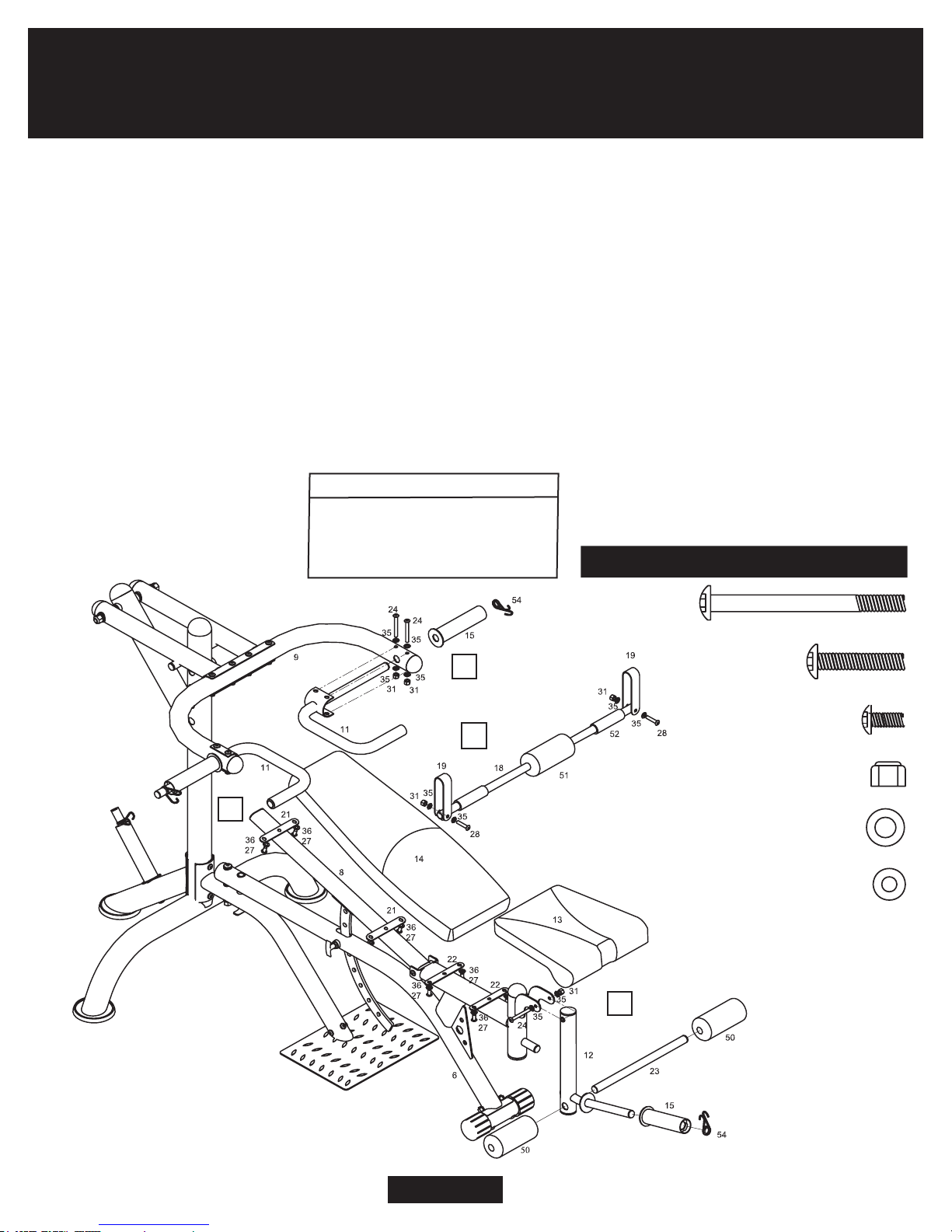
PAD AND BAR ASSEMBLY STEP 4
A
B
C
D
A. Secure the left and right Handle Bars (#11) to the Press Arms (#9) by using four Button Bolts (#24),
eight Washers (#35) and four Nylon Lock Nuts (#31). Slide on the left and right Olympic Adapters
(#15) and secure them with two Quick Clips (#54).
B. Attach the Leg Curl Tube (#12) to the bracket on the Main Fram (#6) using one Button Bolt
(#24), two Washers (#35) and secure with one Nylon Lock Nut (#31). Slide the Roller Tube (#23)
into the Leg Curl Tube (#12) and then slide on the two Foam Rollers (#50) on each end. Slide on
the Olympic Adapter (#15) and secure it with a Quick Clip (#54).
C. Attach Seat Cushion (#13) and Backrest Cushion (#14) with eight Button Bolts (#27) and
eight Washers (#36) from underneath.
D. Attach two Brackets (#19)
to the ends of the Squat Bar
(#18) using two Button Bolts
(#28), four
Washers (#35) and
secure using two Nylon Lock
Nuts (#31).
OLYMPIC ADAPTER
If you intend to use Olympic plates,
slide the Olympic Adapter (#15)
over the standard plate post and
secure with one Spring Clip (#54)
(#24) Button Bolt (3/8'' x 3-1/4'') [5 pieces]
(#28) Button Bolt (3/8'' x 1-7/8'') [2 pieces]
(#27) Button Bolt (5/16" x 5/8") [8 pieces]
(#31) Nylon Lock Nut (3/8" x 11t) [7 pieces]
(#35) Washer (3/8") [14 pieces]
[8 pieces]
(#36) Washer (5/16")
Hardware Required for Step 4
Page 10

FINAL CHECK
• Make sure all bolts are tightened.
• Check for loose parts and components
• Check to see if there are any tears or bends in the welding or metal.
• Be sure that all adjustment locking devices and safety devices are properly
located and fully engaged prior to use!
Page 11
Thanks for choosing
LB2600
Retailer:
Page 12 Version: 02-04-2010
Table of contents
Other Body Champ Home Gym manuals


