Bodyflow CX1 User manual
OPERATIONS MANUAL
Bodyflow®-CX1
00867 AU

Legal Notice
Distribution, reproduction and translation of the software and its documentation (or excerpts
thereof) are prohibited without the prior written consent of Bodyflow International PTY LTD.
Bodyflow International PTY LTD reserves the right to change the software and associated data as
well as the documentation without notice. All other rights reserved.
Bodyflow International PTY LTD
2 Islington Street
Collingwood 3066
Victoria Australia
1300 BODYFLOW
1300 26393569
www.bodyflowinternational.com
DISCLAIMER
The Bodyflow®stimulation unit ("the product") is manufactured in Germany by PHYSIOMED ELEK-
TROMEDIZIN AG and is distributed in Australia by its distributor, Bodyflow International PTY LTD.
Bodyflow International PTY LTD has endeavoured to ensure that the data analysis and assessment
of such data and other information as provided by the manufacturer is accurate.
Any projected information contained in the operating instructions is based on Bodyflow's or
PHYSIOMED ELEKTROMEDIZIN AG's analysis and subjective estimates and assumptions and may
be about circumstances, scenarios and events which may take place. As such, no representations
are made by Bodyflow International PTY LTD or PHYSIOMED ELEKTROMEDIZIN AG as to the accu-
racy of such information.
The product must be used strictly in accordance with the operating instructions. Neither Bodyflow
International PTY LTD or PHYSIOMED ELEKTROMEDIZIN AG will not be liable for any liability arising
from any loss, damage or injury caused through any use of the product outside the scope of the
operating instructions.
To the extent permitted by law, neither PHYSIOMED ELEKTROMEDIZIN AG or Bodyflow Interna-
tional PTY LTD assume any liability for any loss or damages incurred directly or indirectly from any
use of the Product or as a result of any person acting or refraining to act in reliance of any informa-
tion contained in any assessment or operating instructions relating to the Product or in respect of
any negligent act.
Where any Act implies any condition or warranty in respect to the use or supply of the Product,
Bodyflow International PTY LTD's liability will be limited to the re-supply of the relevant Product by
Bodyflow International PTY LTD.
Bodyflow® is made in Germany in compliance with the quality requirements of ISO 9001 and the
applicable safety standards and regulations of the Council Directive 93/42/EEC of 14 June 1993
concerning medical devices.
A conformity check acc. to Annex II, approved by the notified body 1275, was carried out.
Last updated April 9, 2009.

Instrument Overview

Display
Front Panel
3
7
11
10
9
6
5
4
8
2
Rear
Face
1
12
Legend
1 Mains Module 5 Pulse Indicator Circuit 1 9 Output Indicator
2 Display 6 Intensity Control Circuit 2 10 Vacuum Connectors
3 Data Selector 7 Pulse Indicator Circuit 2 11 Patient Lead Connector
4 Intensity Control Circuit 1 8 Patient Current Indicator 12 Water Separator
Symbols
CAUTION!
Please refer to the operating instructions and consider the physiological effects!
Type BF component, not connected to protective ground wire!

Contents
1Introduction ....................................................................................... 1
1.1 Instrument Description .............................................................................. 1
1.2 Application ................................................................................................. 1
1.3 Contraindications (When not to Use this Device) ....................................... 2
2Controls and Indicators...................................................................... 3
2.1 Function of Controls and Indicators ........................................................... 3
2.1.1 Mains Module <1>..................................................................................... 3
2.1.2 Display <2> ............................................................................................. 4
2.1.3 Data Selector <3> .................................................................................... 4
2.1.4 Intensity Control Circuit I <4> and Intensity Control Circuit II <6> .................. 4
2.1.5 Pulse Indicator Circuit I <5> and Pulse Indicator Circuit II <7> ....................... 5
2.1.6 Patient Current Indicator <8> ..................................................................... 5
2.1.7 Output Indicator <9> ................................................................................ 5
2.1.8 Vacuum Connectors <10> .......................................................................... 5
2.1.9 Patient Lead Connector <11> ..................................................................... 6
2.1.10 Water Separator <12>............................................................................... 7
2.2 Overview of Menus..................................................................................... 8
2.2.1 Menu Level 1 ............................................................................................ 8
2.2.2 Menu Level 2 ............................................................................................ 8
2.2.3 Menu Level 3 ............................................................................................ 9
2.2.4 Vacuum Settings ..................................................................................... 10
2.3 On all Menu Levels ................................................................................... 11
2.4 Hierarchy of Menu Levels ......................................................................... 11
3Notes on Operation .......................................................................... 12
3.1 Connection and Start-up .......................................................................... 12
3.1.1 Connecting the Instrument ....................................................................... 12
3.1.2 Instrument Start-up ................................................................................ 12
3.2 Self-Test Routine...................................................................................... 12
3.2.1 Instrument Function Check ....................................................................... 12
3.2.2 Function Check of the Vacuum Unit............................................................ 13
3.2.3 Checking Vacuum Hoses........................................................................... 14
3.3 Instrument Errors .................................................................................... 15
4Therapy ............................................................................................ 16
4.1 Preparations and Attaching the Electrodes .............................................. 16
4.1.1 Adhesive Electrodes................................................................................. 16
4.1.2 Vacuum Electrodes .................................................................................. 16
4.2 Selecting Therapy Parameters ................................................................. 17
4.2.1 Direct Access to Therapy .......................................................................... 17
4.2.2 Access via electrode placement ................................................................. 18
5Setup Menu ...................................................................................... 19
6General Notes .................................................................................. 20
7Service, Repairs, Maintenance.......................................................... 20
8Cleaning and Disinfection................................................................. 21
9Disposal ........................................................................................... 21

10 Technical Data.................................................................................. 22
10.1 Manufacturer......................................................................................... 22
11 Service Life ...................................................................................... 23
12 Electromagnetic Compatibility.......................................................... 23
13 Training............................................................................................ 23
14 Accessories ...................................................................................... 24
14.1 Standard Accessories ............................................................................ 24
14.2 Additional Accessories........................................................................... 25
15 Index ............................................................................................... 26

Introduction
1Introduction
With your Bodyflow®-CX1, you have acquired a high-quality and extremely versa-
tile unit for stimulation current therapy.
The instrument will only show its true potential, however, if you are well informed
about its functions. For this reason, carefully read the Operating Instructions and
make yourself familiar with the use of the instrument.
1.1 Instrument Description
Bodyflow®-CX1 is an electrical stimulator for therapy with low-frequency currents.
The stimulation current can either be applied via adhesive electrodes or by means
of vacuum electrodes. The instrument is equipped with a vacuum unit.
Bodyflow®-CX1 is controlled in its functions by a microprocessor. Important parts
are permanently monitored by the processor and faulty operation is prevented. Af-
ter switching on, all instrument functions are checked during an automatic self-test
routine. The instrument complies with all current safety standards.
The instrument complies with all requirements of the European regulation
93/42/EEC and is therefore CE labelled.
1.2 Application
Bodyflow®-CX1, the new generation of instruments to stimulate the lymphatic sys-
tem, was developed with the target of re-establishing the dynamic equilibrium of
all bodily liquids and thus the functional quality of the different types of tissue
treated. Thanks to its ganglionic pumping activity at the 4 electrodes and its dual
treatment options (light and standard), the instrument offers a wide variety of ap-
plications in the therapeutic and aesthetic field. Specific for the Bodyflow®-CX1 in-
strument is a current form reproducing the impulses of the nervous system to the
muscular texture, thus activating the natural peristaltism of the system as well as
re-educating the circulatory functions.
Bodyflow®-CX1 drains and removes surplus hydride mass, metabolic waste, exu-
date resulting from the micronization of triglycerides, and regulates circulatory
problems on a long-term basis.
It allows for a re-establishing of the qualities and functions of the various tissues
treated and is conducive to the drainage circuits - in arterial supply and in lym-
phatic and venous return. This activation of the drainage circuits reactivates all cel-
lular exchange processes the objective of all therapeutic and aesthetic treatments.
Warning
The instrument may only be operated by qualified personnel who
have undergone special training!
BodyflowTM-CX1 1

Introduction
1.3 Contraindications (When not to Use this Device)
Bodyflow®-CX1 therapy must not be used on patients who:
• have an internal cardiac device such as a permanent pacemaker or internal
defibrilator,
• are pregnant,
• are suspected of suffering from venous thrombosis or Deep Vein Thrombosis
(DVT),
• have been diagnosed with an active malignant disease process,
• have a highly inflammatory, fever-prone disorder.
Vacuum electrodes must not be used:
•in the vicinity of varicose veins
•in cases of venous inflammations and other vascular diseases.
2 BodyflowTM-CX1
Controls and Indicators
2Controls and Indicators
As its LCD is divided into different function fields, Bodyflow®-CX1 allows for
clear and easy operation.
The plastic housing and the front panel protect the electronic components and
simplify cleaning.
Safety-related components are continuously monitored by the microprocessor,
erroneously initiated operating steps are suppressed, a self-test routine is
performed after switching on and possible malfunctions are displayed. For
safety reasons, the stimulation current output is automatically cut off in the
event of a malfunction.
2.1 Function of Controls and Indicators
In the following section we will introduce the individual controls of Bodyflow®-
CX1. The numbers in angle brackets refer to the Instrument Overview at the
beginning of this manual.
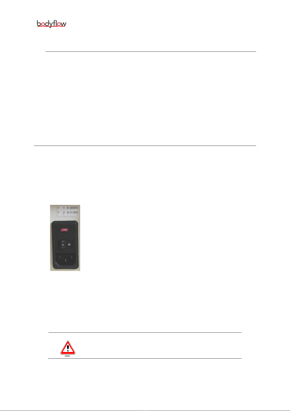
2.1.1 Mains Module <1>
The mains module <1> with mains supply, fuses and mains
switch is situated at the rear side of the instrument.
For the mains supply, please only use the mains cable pro-
vided by the manufacturer.
Bodyflow®-CX1 is switched on and off using the integrated
mains switch. After switching on, a self-test is automatically
carried out by the instrument (refer to Instrument Function
Check on page 12).
Setting the Line Voltage
After replacing the fuses, you can run the instrument with 115 V as well as
230 V simply by using the rotatable fuse carrier at the mains module <1>.
Replace 2 A fuses with 1 A fuses, turn the fuse carrier by 180° and insert it
again, so that the “red window” of the mains module <1> reads “230 V”,
after the cover has been closed again.
Warning
Set the line voltage at the mains module to match the in-
coming line voltage!
BodyflowTM-CX1 3

Controls and Indicators
2.1.2 Display <2>
Display <2>
On the display <2>, you can select all of the instrument’s menus and pa-
rameters on different levels. The selection is carried out with the data se-
lector <3>.
2.1.3 Data Selector <3>
Use the data selector <3> to select the therapy pa-
rameters and to operate the instrument by means of
the cursor.
You can move the cursor to the individual menu items
by turning the selector to the right or left. To select a
menu or a function, simply press the selector.
To select a parameter, move the cursor to the respective field by turning
the selector. After pressing the selector, the cursor will start flashing. You
will then be able to select the parameters by turning the selector. Confirm
the selected value by pressing the selector again (cursor stops flashing).
The modified values are displayed at the respective position of the display
<2>.
2.1.4 Intensity Control Circuit I <4> and Intensity Control Circuit
II <6>
The intensity control circuit I <4> and intensity
control circuit II <6> serve to set the current inten-
sity in both circuits in steps of 1 mA. With turning up
one control, the respective therapy timer in the dis-
play <2> is started.
Whenever you have to turn down intensity control circuit I <4> and in-
tensity control circuit II <6> to “0”, the following turn-down signal is
displayed on the display <2>:
Automatic Output Current Switch-off
Bodyflow®-CX1 has an Automatic Output Current Switch-off function,
responding when the current of the electrodes is interrupted (electrode falls
off, plug is disconnected from patient lead etc.). In the display <2>, you
are then prompted to CHECK ELECTRODES and the current is automatically
turned down to a low basic current. After eliminating the error, the current
will automatically be surged to the previously set value and the message
will disappear.
4 BodyflowTM-CX1

Controls and Indicators
2.1.5 Pulse Indicator Circuit I <5> and Pulse Indicator Circuit II
<7>
The pulse indicator circuit I <5> and the pulse in-
dicator circuit II <7> serve for visual control of the
current forms and pulses. They flash whenever a pulse
is generated by the processor, even in case of zero in-
tensity. It will stop flashing, however, when the inten-
sity is automatically reduced by the therapy timer. Af-
ter turning back the intensity to 0 with the intensity
control circuit I <4> or intensity control circuit II
<6>, the respective indicator will be illuminated again.
2.1.6 Patient Current Indicator <8>
The flashing of the indicator is dependent on the resis-
tance in the circuit. In most cases the diodes start flash-
ing exactly at the moment when the patient starts to
have a clear sensation of the current.
If the indicator does not flash during treatment, you must carry out a
self-test and observe whether or not the indicator flashes. If the indi-
cator still does not flash during treatment after the check, the accesso-
ries (e.g. electrodes) should be checked and replaced if necessary.
2.1.7 Output Indicator <9>
The indicator tells you to be cautious when handling the
electrodes:
Warning! Voltage is applied to the patient lead connec-
tor <11> or at the vacuum connectors <10>!
2.1.8 Vacuum Connectors <10>
The vacuum connectors
<10> serve to connect the
vacuum electrode cables, i.e.
the connecting parts to the vac-
uum electrodes.
The connectors 1+2 form circuit I (red) while the connectors 3+4
(black) form circuit II.
The colour marks of the vacuum electrode cables facilitate assignment
of the individual electrode cables or electrodes.
The vacuum electrodes are activated by means of the corresponding
icon in the menus of the therapy forms STANDARD and LIGHT. If the
vacuum electrodes are activated stimulation current is also transferred
via the adhesive electrodes that are connected to the patient lead
connector <11>. This enables a combined use of vacuum and adhe-
sive electrodes.
Warning The automatic output current switch-off is not active
BodyflowTM-CX1 5

Controls and Indicators
when working with a second pair of electrodes (vacuum
and adhesive electrodes) in one of the two channels!
Warning
Please ensure you do not touch the electrodes when the
current is turned up!
2.1.9 Patient Lead Connector <11>
The patient lead connector <11> serves to plug in the
patient lead. You can plug adhesive electrodes into the
patient lead.
Switching between vacuum electrodes and patient lead is
done via the respective icons in the menus of the therapy
forms STANDARD and LIGHT.
If the electrodes that are connected to the patient lead connector <11>
are activated, stimulation current is also transferred via the vacuum elec-
trodes (provided that the vacuum electrodes are attached).
Warning
The automatic output current switch-off is not active
when working with a second pair of electrodes (vacuum
and adhesive electrodes) in one of the two channels!
Patient Lead - Mode(s) of Attachment
The numbers of the connectors facilitate easy
and correct attachment of the electrodes to
the two circuits.
Connectors 1 +2: Circuit I
Connectors 3 +4: Circuit II
Type BF component, not connected to protective ground
wire.
6 BodyflowTM-CX1

Controls and Indicators
2.1.10 Water Separator <12>
The water separator <12> protects the function of the
pump by holding back the water coming from the moist
sponges.
The container should be emptied occasionally. To empty
the water separator, pull down the container.
Prior to removing the water separator, turn off the in-
strument and unplug the power cable!
After emptying, reinstall the water separator firmly , plug
in the power cable and switch on the instrument on the
mains module <1>.
The level measurement guarantees, by means of automatically switch-
ing off the instrument, that the water does not exceed a certain level and
no water gets into the instruments.
When the instrument is turned off, an audible signal is issued and the
H2Oindicator integrated in the top of the water separator is illuminated.
The indicator is turned off after the water separator is emptied.
BodyflowTM-CX1 7

Controls and Indicators
2.2 Overview of Menus
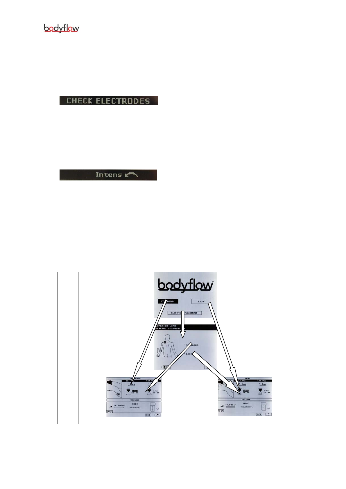
2.2.1 Menu Level 1
The following functions are available on level 1:
Direct access to level 3
(therapy program STANDARD)
Direct access to level 3
(therapy program LIGHT)
Access to level 2 (ELECTRODE PLACEMENT menu
displaying patterns for electrode placement)
2.2.2 Menu Level 2
The image shows where to attach the electrodes in various body re-
gions. The following functions are available on level 2:
Direct access to level 3
(therapy program STANDARD)
Direct access to level 3
(therapy program LIGHT)
Number of current therapy example
Scrolls to other examples of electrode placement
Return to level 1
8 BodyflowTM-CX1

Controls and Indicators
2.2.3 Menu Level 3
The actual treatment is performed on menu level 3. The following func-
tions are available:
The therapy timer can be set to values between 1 minute
and 59 minutes in steps of 1 minute.
During treatment, therapy time may be shortened at any
time, but it cannot be prolonged with intensity turned high
(intensity control <4> and intensity control II <6>).
The timer starts running when intensity is turned high. At
the end of therapy the timer issues an acoustic signal and
slowly reduces the intensity. Turning the intensity in a cir-
cuit back to 0 causes the timer to return to its previous set-
ting.
Makes pulse trains and their polarity visible
The value above the rectangle indicates the present inten-
sity in mA (intensity control I <4> or intensity control
II <6>) and the present polarity of the red connectors of
the patient lead (patient lead connector <11> or vac-
uum connectors <10>).
Settings for vacuum
Takes you to the setup menu (page 19)
Return to level 1
BodyflowTM-CX1 9
Controls and Indicators
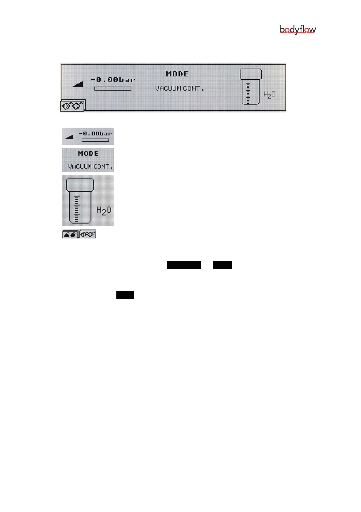
2.2.4 Vacuum Settings
On menu level 3 you can set the following vacuum parameters:
Pressure indicator (the minus sign means vacuum)
Mode (continuous, or pulsed with 8 min-1)
Water separator status
Symbol depicting vacuum electrodes or adhesive
electrodes
To switch the instrument to vacuum electrodes:
(1) Go to the therapy program STANDARD or LIGHT.
(2) Rotate the data selector <3> to move to the vacuum section.
(3) Set the vacuum strength with the data selector <3>.
(4) Click on the MODE icon and set the vacuum mode (either continu-
ous or pulsed).
As long as the vacuum electrodes are activated, a corresponding icon
is displayed in the menu.
10 BodyflowTM-CX1
Controls and Indicators
2.3 On all Menu Levels
The following messages can be displayed on all menu levels. They
have the following meaning:
When this message flashes, turn the
intensity to zero. In the event therapy
has been completed and this message
is flashing, the automatic switch-off
mechanism will be activated and the
intensity must then also be turned to
0. The automatic output current
switch-off has interrupted pulse out-
put.
When this message flashes, turn the
intensity to zero. This may be neces-
sary if the automatic switch-off is acti-
vated as soon as the therapy is fin-
ished.
2.4 Hierarchy of Menu Levels
The following diagram shows the hierarchy of the various menu levels
and their functions:
Menu
Level
1
Menu
Level
2
Menu
Level
3
BodyflowTM-CX1 11

Notes on Operation
3Notes on Operation
3.1 Connection and Start-up
3.1.1 Connecting the Instrument
(1) Ensure that the operating voltage of the instrument (see red win-
dow in the mains module <1>) matches the line voltage.
(2) Plug the supplied mains lead firmly into the rear face of the in-
strument (mains module <1>) and connect it to the socket. A
safe connection is established via a grounding socket outlet with
protective wire.
3.1.2 Instrument Start-up
(1) Make sure that the instrument is switched off.
(2) Turn the intensity control I <4> and intensity control II <6>
down to 0.
(3) Switch on the instrument with the mains switch (mains module
<1>).
The instrument will carry out an automatic self-test routine during
which all functions and output values are checked.
(4) Proceed as described in section Therapy on page 16.
3.2 Self-Test Routine
3.2.1 Instrument Function Check
(1) Turn the intensity control I <4> and intensity control II <6>
down to 0.
(2) Switch the instrument off and on with the mains switch (mains
module <1>).
The instrument will carry out an automatic self-test routine during
which all functions and output values are checked. An audible sig-
nal is issued.
The instrument is ready now. You are on menu level 1.
12 BodyflowTM-CX1
Notes on Operation
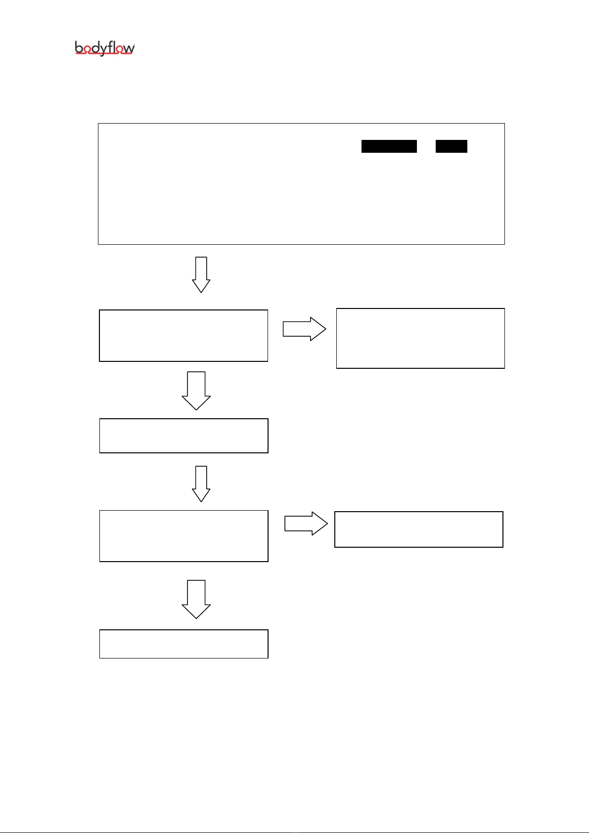
3.2.2 Function Check of the Vacuum Unit
(1) Switch on the instrument (mains module <1>).
(2) Select one of the treatment modes STANDARD or LIGHT
and ensure that the vacuum unit is not yet active (refer
to Vacuum Settings on page 10).
(3) Close the vacuum connectors <10> with the sup-
plied bypath hose.
(4) Activate the vacuum unit and set the vacuum in the
continuous mode to the maximum value.
Check the water separator
<12> for tight fixing and cracks.
Replace it, if necessary.
Does the display show a value of
–0.60 bar for the vacuum?
Is the pump audible?
No
Yes
Turn the vacuum to pulsation
mode.
Does the value indicated for the
vacuum waver
between -0.1 and –0.6 bar?
Contact your service partner!
No
Yes
The instrument is in order.
BodyflowTM-CX1 13
Notes on Operation
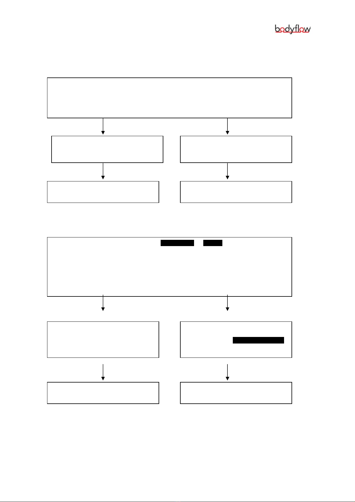
3.2.3 Checking Vacuum Hoses
3.2.3.1 Checking for Condition
(1) Close the circuit I with the supplied double bypath hose.
(2) Short-circuit the circuit II with the vacuum hose to be checked.
(i.e. plug one side into connector 3 and the other side into connector 4).
(3) Set the vacuum to –0,4 bar (refer to Vacuum Settings on page 15).
Does the display show a constant
vacuum intensity of –0,4 bar?
Does the indicated vacuum waver
(with the vacuum pump working con-
stantly)?
The vacuum electrode hose is OK. You must replace the vacuum elec-
trode hose.
3.2.3.2 Checking for Conductivity
(1) Select one of the treatment modes STANDARD or LIGHT.
(2) Activate the vacuum unit.
(3) Short-circuit the circuits I and II with the vacuum electrode hose to be checked
(i.e. plug one side into the connector 1 or 3 and the other side
into connector 2 or 4).
(4) Set the intensities of both circuits to the desired value.
The patient current indicator <8>
is constantly on.
The instrument is working properly.
The patient current indicator <8>
is flashing instead of being constantly
on. The message Check Electrodes
is shown on the display.
The vacuum electrode hose is OK. You must replace the vacuum elec-
trode hose.
14 BodyflowTM-CX1
Table of contents
Popular Fitness Equipment manuals by other brands

Current Solutions
Current Solutions InTENSity Twin Stim III user manual

Insportline
Insportline Holister user manual

BRONZE GYM
BRONZE GYM MV-015 user manual

Body Sculpture
Body Sculpture Core Trimmer Plus manual

Weider
Weider 130 Tc Bench Gebruiksaanwijzing

Keys Fitness
Keys Fitness Leg Attachment KF-LEGA owner's manual


