BOESCH BC Series User manual
OPERATION
AND
MAINTENANCE
MANUAL
BC SERIES
2" Full Passage
Submersible Sewage
Pump

3
Instruction Manual
2" Full Passage Submersible Sewage Pump
BC SERIES
INDEX
Introduction................................PAGE 3
Specifications….........................PAGE 3
Installation .................................PAGE 4
Electrical wiring..........................PAGE4
Operation…………………………PAGE5
Maintenance...........................PAGE 5
Construction ........................... PAGE 6
Disassembly and Assembly… PAGE 10
Nameplate format… ...............PAGE 10
Troubleshooting......................PAGE 11
Introduction
Check the following upon delivery:
1. Is the pump exactly what you ordered? Check nameplate. It is especially important that you
check whether the pump is to be used with 50 or 60 Hz.
2. Has any damage occurred during shipment? Are any bolts or nutsloose?
3. Have all necessary accessories been supplied?
(For a list of standard accessories see Construction section.)
We recommend that you keep a spare pump on hand in case of emergencies.
Keep this instruction manual in a safe place for future reference.
Specifications
Check the nameplate for your pump’s head (Hmax), discharge volume (Qmax), speed (R.P.M.),
motor voltage and current.
Other specifications are noted in the chart below.
Item
Specifications
Liquid handled
Type
Sewage, wastewater, miscellaneous drain water
Temperature
Non-Automation
0.5~2 HP
32~104˚F(0~40˚C)
Automation
0.5~2 HP
32~104˚F(0~40˚C)
Materials
Pump Casing
EN-GJL-200
Impeller
EN-GJL-200
Shaft
AISI 410 stainless steel
Motor type
Dry type submersible motor
Shaft seal lubrication oil
Turbine No.32 ISO VG-32
Maximum water depth
33 ft (10 m)

4
Installation
Check the following before beginning installation:
Insulation resistance measurement
Place the pump on a dry surface. For this test neither the motor nor the cable should be
immersed in water. Use a megger to measure the insulation resistance between ground and each
phase of the motor. Do the same with any two phases until all pairs are completed. The megger
should indicate an insulation resistance of no less than 20 mega ohms. While taking the
measurement, keep the power supply cable off the ground.
Installation
1. WARNING: Under no circumstances should cable be pulled while the pump is being moved
or installed.
Attach a chain or rope to the grip and install the pump.
2. This pump must not be installed on its side or dry operated.
Ensure that it is installed upright on a secure base.
3.
Install the pump in the tank where there is the least turbulence.
4.
Install piping so that air will not be entrapped. If piping must be installed in such a way that air
pockets are unavoidable, install an air release valve wherever such air pockets are most likelyto
develop.
5.
Do not permit end of discharge piping to be submerged,as backflow will result when the
pump is shut down.
6.
WARNING: Do not operate the pump for more than 2 minutes with the water level near the
lowest water level(H1) as shownon Fig.1.
7.
Use Fig. 2 for set up of floats to maintain safe operating water levels.
H1: Lowest water level (Motor flange)
H2: Operating water level
This must be above the top of the motor.
Fig. 1
Fig. 2
5
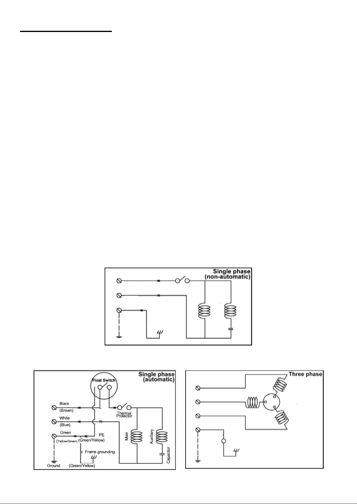
Electrical wiring
Wiring
A)
Wire as indicated for the appropriate start system as shown in Fig-3 & 4 for single phase
version and Fig-5 for three phases.
B)
Loose connections will stop the pump. Make sure all electrical connections are secure.
C)
For three phase motors - Operate the pump for a short time (1 or 2 seconds) to verify the
rotation of direction of the impeller, switch two of the three power cords to correct the rotation
if necessary.
D)
Make sure to check the pump’s direction of rotation with the pump exposed to the
atmosphere. Operating the pump with reversed rotation while in submerged conditions under
water will most likely damage the pump, which will lead to leakage and electrical shock.
Cable
WARNING: Never let the end of the cable contact water.
A)
Do not immerse any splicing in water.
B)
Do not pull power cable. Use the pump handle.
C)
Do not expose any cables to sunlight.
Grounding
Yellow/green cable should be connected to ground. Under no circumstances should the green
(yellow/green) wire be connected to the power supply.
WARNING: Use short circuit breakers to prevent danger of electrical shock.
WARNING: Never start the pump while it is suspended, as the pump may jerk and cause serious
accident involving injury.
Fig-3
Fig-5
Black
L
L
N
N
PE
(Brown)
(Brown) Thermal
Thermal
White p(Blue)
Green
(Yellow/Green)
Frame
(Green/Yellow)
(Green/Yellow)
Red
R
T
PE
White
Black
Green
(Yellow/Green)
Ground
U
V
W
Frame grounding
(Green/Yellow)
V2 U2
Overload protector
W2
Main
Auxiliary
Capacitor
Auxiliary
Capacitor
Main
Thermal
Thermal
Protector
Black
(Brown)
White
(Blue)
Green
(Yellow/Green)
Frame Grounding
(Green/Yellow)
PE
N
N
L
L
Ground
U2
Overload protector
W2
V2
U
V
Red
W
White
Black
R
T
PE Green
(Yellow/Green)
Frame grounding
(Green/Yellow)
Ground
S
Fig-4
6
Operation
1.
Before starting the pump
a)
After installation, measure the insulation resistance again.
b)
Check water level.
If the pump is operated continuously for an extended period of time in a dry condition or at the
lowest water level, the motor protector will be activated. Constant repetition of this action will
shorten pump service life.
2.
Test operation
Non-automatic pump (BC)
Automatic pump (BC-Automatic)
a)
Turn the operating switch on and off a couple of times to check for
normal pump start. Float switch must be raised for the pump to start.
b)
Next, check direction of rotation. If discharge volume is low, reverse two of thewires.
Maintenance
Check pressure, flow, voltage and current.
Refer to Troubleshooting section for recommendations.
1.
Daily inspections
Check current fluctuation daily. If current fluctuation is great, even though within the limits, foreign
matter may be clogging the pump. If the quantity of liquid discharged falls suddenly, foreign
matter may be blocking the suction inlet.
2.
Regular inspections
Monthly inspections
Measure insulation resistance as previously described.
Annual inspections
To prolong the service life of the mechanical seal, replace the oil in the mechanical seal chamber
once a year. Cloudy oil is an indication of a defective mechanical seal requiring replacement.
When replacing the oil, lay the pump on its side with filler plug on top. Fill suitable amount turbine
oil No.32 (ISO VG-32)
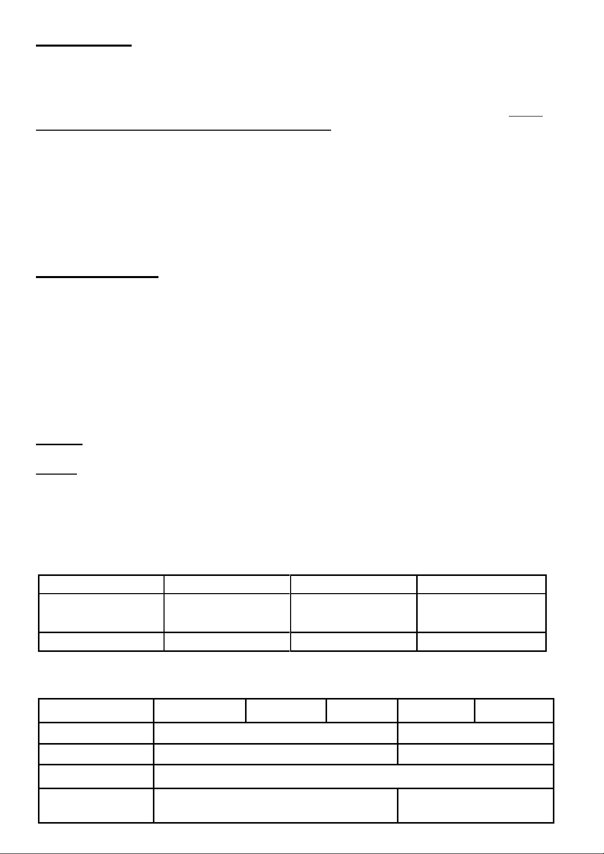
Replacement of Parts
Replace the appropriate part when the following conditions appear:
Replacement part
Mechanical seal
Oil filler plug O-ring
Lubricating oil
Condition
Oil in mechanical seal
chamber
Inspect or replace the oil
Oil is cloudy or
dirty
Frequency
Annual
6 months
6 months
Note: above replacement schedule is based on normal operating conditions.
Motor output
0.5HP
0.75HP
1HP
1.5HP
2HP
Mechanical seal
14Ø
15Ø
Lip seal
14Øx 24Øx 5 t
15Øx 24Øx 7 t
Oil filler plug O-ring
(Inner diameter) x (outer diameter) x (thickness) = 7.52Øx14.5Øx3.53 t
Lubricating oil
(turbine oil #32)
192 cc
280 cc
7
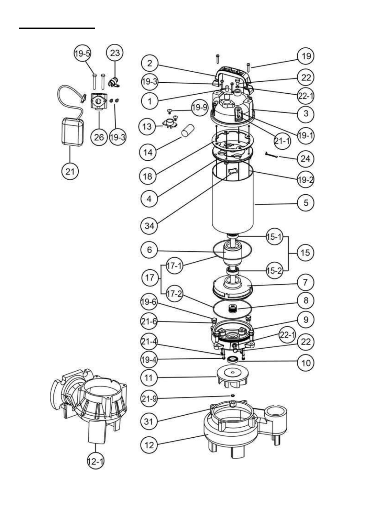
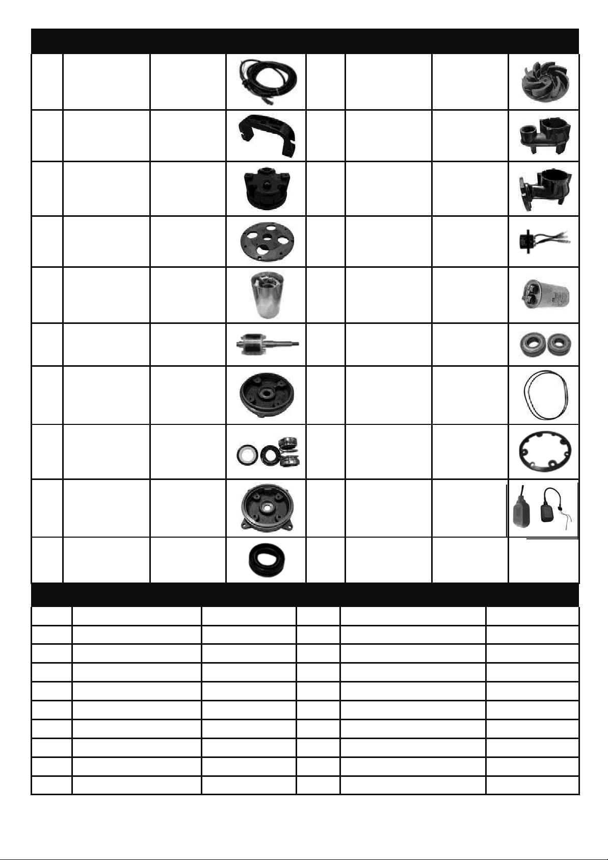
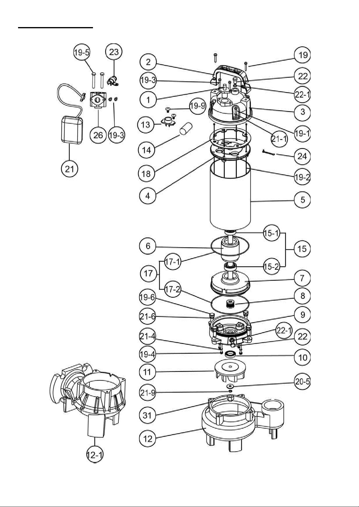
Construction
BC SERIES 0.5~1HP
8
NO
Part
Material
Photo
NO
Part
Material
Photo
1
Cable
H07RN-F/
SJTOW/
STOW
11
Impeller
EN-GJL-200
2
Handle
Nylon 6
12
Pump Casing
EN-GJL-200
3
Motor
Cover
PA66+
30GF
12-1
Pump Casing
(Horizontal)
EN-GJL-200
4
Bracket
EN-GJL-200
13
Protector
(3 Phase)
KLIXON
5
Motor Housing
+ Stator
AISI 304
14
Capacitor
(1 Phase)
-
6
Shaft
with Rotor
AISI 410
15-1
15-2
Upper Bearing
Lower Bearing
NTN/TPI
7
Oil Chamber
EN-GJL-200
17-1
17-2
O-ring
NBR
8
Mechanical
Seal
CA/CE
+
SIC/SIC
18
Gasket
NBR
9
Seal Housing
EN-GJL-200
21
Float Switch
(Optional)
-
10
Lip Seal
NBR
NO
Part
Material
NO
Part
Material
19
Screw
AISI 304
21-6
Spring Washer
AISI 304
19-1
Screw
AISI 304
21-9
Spring Washer
AISI 304
19-2
Long Screw of motor
Steel
22
Oil Filler Plug
AISI 304
19-3
Screw
AISI 304
22-1
O-ring of Oil Filler Plug
NBR
19-4
Screw
AISI 304
23
Cable Seat
-
19-5
Screw
AISI 304
24
Wire and Screw
Steel
19-6
Screw
AISI 304
26
T adapter (Optional)
-
19-9
Screw
Steel
31
Nut of impeller
AISI 304
21-1
Spring Washer
AISI 304
34
Corrugated Spring
Steel
21-4
O-ring
NBR
9
Construction
BC SERIES 1.5~2HP

10
NO
Part Material Photo
NO
Part
Material
Photo
1
Cable
H07RN-F/
SJTOW/
STOW
11
Impeller
EN-GJL-200
2
Handle
Nylon 6
12
Pump Casing
EN-GJL-200
3
Motor
Cover
EN-GJL-200
12-1
Pump Casing
(Horizontal)
EN-GJL-200
4
Bracket
EN-GJL-200
13
Protector
(3 Phase)
KLIXON
5
Motor Housing
+ Stator
AISI 304
14
Capacitor
(1 Phase)
-
6
Shaft
with Rotor
AISI 410
15-1
15-2
Upper Bearing
Lower Bearing
NTN/TPI
7
Oil Chamber
EN-GJL-200
17-1
17-2
O-ring
NBR
8
Mechanical
Seal
CA/CE
+
SIC/SIC
18
Gasket
NBR
9
Seal Housing
EN-GJL-200
21
Float Switch
(Optional)
-
10
Lip Seal
NBR
NO
Part Material
NO
Part
Material
19
Screw
AISI 304
21-4
Washer with O-ring
AISI 304+NBR
19-1
Screw
AISI 304
21-6
Spring Washer
AISI 304
19-2
Long Screw of motor
Steel
21-9
Spring Washer
AISI 304
19-3
Screw
AISI 304
22
Oil Filler Plug
AISI 304
19-4
Screw
AISI304
22-1
O-ring of Oil Filler Plug
NBR
19-5
Screw
AISI 304
23
Cable Seat
-
19-6
Screw
AISI 304
24
Wire and Screw
Steel
19-9
Screw
Steel
26
T adapter (Optional)
-
20-5
Washer
AISI 304
31
Nut of impeller
AISI 304
21-1
Spring Washer
AISI 304

11
Disassembly and Assembly
1.
Disassembly
When disassembling pump, have a piece of cardboard or wooden board ready to place the
different parts on as you work. Do not pile parts on top of each other. They should be laid out
neatly in rows. The “O” ring and gasket cannot be used again once they are removed.
Have replacement parts ready. Disassemble in the following order, referring to the sectional view.
Be sure to turn off power source before starting disassembly.
(a)
Remove pump casing bolts, raise the motor section, and remove pumpcasing.
(b)
Remove shaft head bolt and impeller.
(c)
Remove oil filler plug and drain lubricating oil.
(d)
Remove intermediate casing bolts and intermediate oil chamber.
(Remember that any lubricating oil remaining in the mechanical seal chamber will flow out.)
(e)
Carefully remove mechanical seal, taking care not to scratch sliding surface or motorshaft.
2.
Assembly
Re-assemble in reverse order of disassembly.
(a)
During re-assembly, rotate the impeller by hand and check for smooth rotation. If rotation is not
smooth, perform steps-(3) through -(5) again.
(b)
Upon completion rotate the impeller by hand from the suction inlet and check that it rotates
smoothly.
Please obtain “O” rings, shaft seals and other parts from your dealer. Refer to part lists
attached.
Nameplate format
MODEL:
MADE IN TAIWAN
P2: kW
HP
QMAX:
GPM
V HZ
PHASE
HMAX:
FT
FLA:
A
RPM:
RPM
WEIGHT:
LBS
S.NO:
12
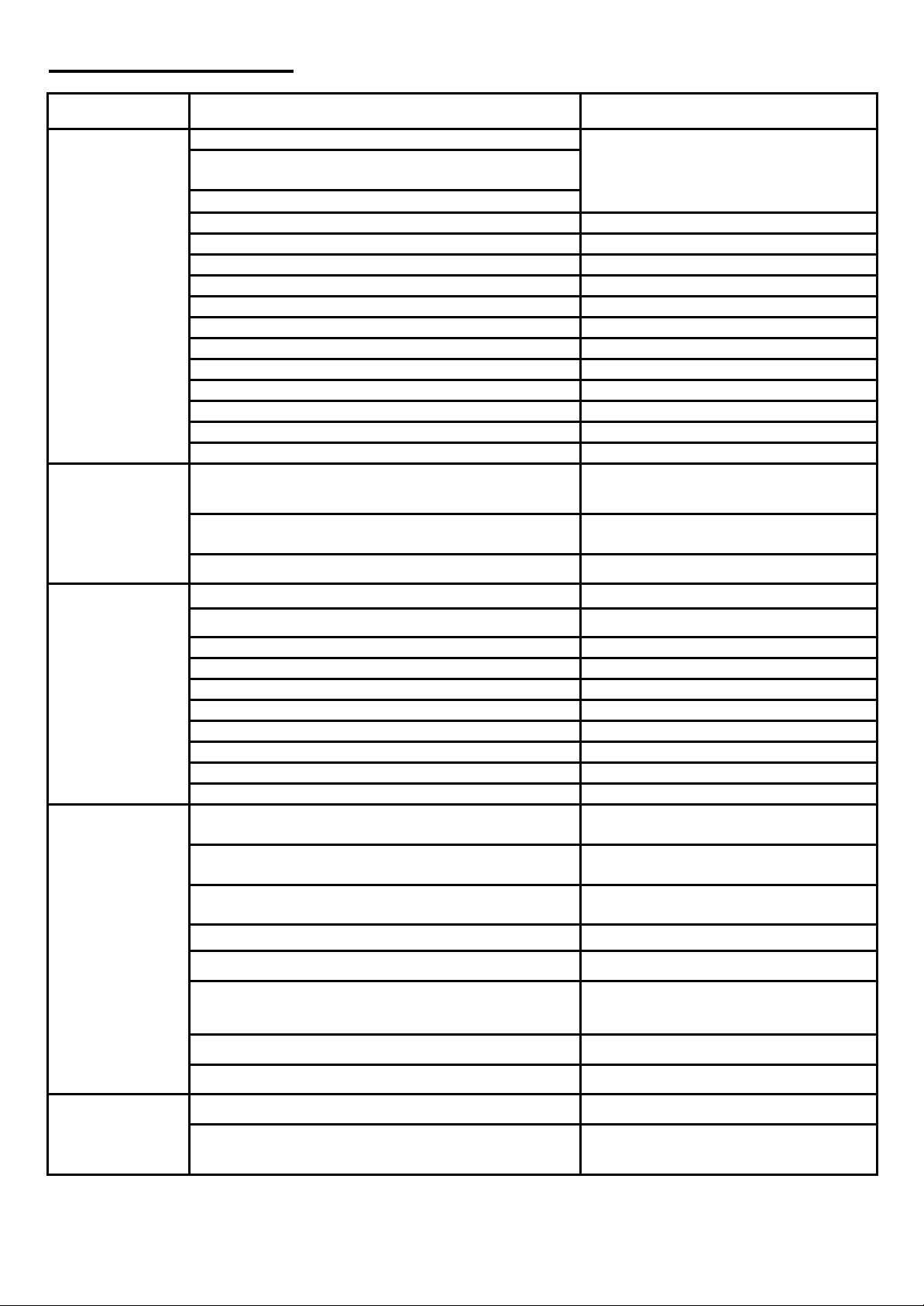
Troubleshooting
Trouble
Cause
Remedy
Does not start.
Starts, but im-
mediately stops.
(1) Power failure
(1)~(3) Check power supply.
(2) Voltage varies more than 10% of nominal value
(3) Significant drop in voltage
(4) Motor phase malfunction
(4) Inspect electrical circuit
(5) Electric circuit connection faulty
(5) Correct wiring
(6) Faulty connection of control circuit
(6) Inspect connections and magnetic coil
(7) Fuses are blown
(7) Check circuit then replace fuse
(8) Faulty magnetic switch
(8) Replace with correct switch
(9) Water is not at level indicated by Float
(9) Raise water level
(10) Float is not at appropriate level
(10) Adjust the position of float
(11) Float is not effective
(11) Repair or replace
(12) Short circuit breaker is activated
(12) Repair location of short circuit
(13) Foreign matter clogging pump
(13) Remove foreign matter
(14) Motor burned out
(14) Repair or replace
(15) Motor bearing broken
(15) Repair or replace
Operates, but
stops after a
while.
(1) Prolonged dry operation has activated motor protec-
tor and caused pump to stop
(1) Raise water level to C.W.L
(2) High liquid temperature has activated motor protec-
tor and caused pump to stop
(2) Lower liquid temperature
(3) Reverse rotation
(3) Correct rotation
Does not pump.
Inadequate vol-
ume.
(1) Reverse rotation
(1) Correct rotation (see Operation)
(2) Significant drop in voltage
(2) Check power supply
(3) Operating a 60Hz pump with 50Hz
(3) Check nameplate
(4) Discharge head is high
(4) Recalculate and adjust operating point
(5) Low operating water level causes air suction
(5) Raise water level or lower pump
(6) Leaking from discharge piping
(6) Inspect, repair
(7) Clogging of discharge piping
(7) Remove foreign matter
(8) Foreign matter in suction inlet
(8) Remove foreign matter
(9) Foreign matter clogging pump
(9) Remove foreign matter
(10) Worn impeller
(10) Replace impeller
Over load
(1) Unbalanced current and voltage
(1) Check power supply
(2) Significant voltage drop
(2) Check power supply
(3) Motor phase malfunction
(3) Inspect connections and magnetic
switch
(4) Operating 50Hz pump on 60Hz
(4) Check nameplate
(5) Reverse rotation
(5) Correct rotation (see Operation)
(6) Low head. Excessive volume of water
(6) Replace pump with high head pump
(7) Foreign matter clogging pump
(7) Remove foreign matter
(8) Motor bearing is worn out or damaged
(8) Replace bearing
Pump vibrates;
excessive oper-
ating noise.
(1) Reverse rotation
(1) Correct rotation
(2) Pump clogged with foreign matter
(2) Disassemble and remove foreign
matter

Table of contents
Popular Water Pump manuals by other brands

Super Ego
Super Ego Sego Drain 200 A instruction manual

AstroAI
AstroAI DM1 user manual

Ampco Pumps Company
Ampco Pumps Company ZP2 Series Installation and maintenance manual

Johnson Pump
Johnson Pump F7B-5001 instruction manual

DAYLIFF
DAYLIFF DHF Installation & operating manual

Wilden
Wilden Advanced P100 Series Engineering, operation & maintenance


