manuals.online logo
Brands
  1. Home
  2. •
  3. Brands
  4. •
  5. Sealey
  6. •
  7. Water Pump
  8. •
  9. Sealey TP96.V3 User manual

Sealey TP96.V3 User manual

This manual suits for next models

1

Other Sealey Water Pump manuals

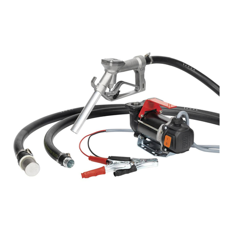
Sealey AK457D User manual

Sealey

Sealey AK457D User manual

Sealey WPS060.V2 User manual

Sealey

Sealey WPS060.V2 User manual

Sealey EWP050 User manual

Sealey

Sealey EWP050 User manual

Sealey ADBLUE TP9912 User manual

Sealey

Sealey ADBLUE TP9912 User manual

Sealey TP6801.V2 User manual

Sealey

Sealey TP6801.V2 User manual

Sealey WPC100A.V2 User manual

Sealey

Sealey WPC100A.V2 User manual

Sealey AK4555D.V2 User manual

Sealey

Sealey AK4555D.V2 User manual

Sealey TP9912 User manual

Sealey

Sealey TP9912 User manual

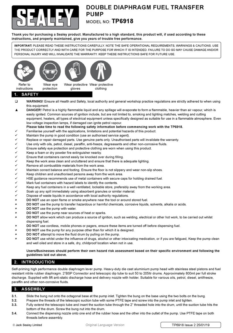
Sealey TP6918 User manual

Sealey

Sealey TP6918 User manual

Sealey TP6818.V2 User manual

Sealey

Sealey TP6818.V2 User manual

Sealey TP51.V2 User manual

Sealey

Sealey TP51.V2 User manual

Sealey TP6807 User manual

Sealey

Sealey TP6807 User manual

Sealey WPD235A.V2 User manual

Sealey

Sealey WPD235A.V2 User manual

Sealey WPCD215 User manual

Sealey

Sealey WPCD215 User manual

Sealey WPD415 User manual

Sealey

Sealey WPD415 User manual

Sealey TP9424.V2 User manual

Sealey

Sealey TP9424.V2 User manual

Sealey PW12CC User manual

Sealey

Sealey PW12CC User manual

Sealey AK456 User manual

Sealey

Sealey AK456 User manual

Sealey WPL117A User manual

Sealey

Sealey WPL117A User manual

Sealey WPD235A.V2 User manual

Sealey

Sealey WPD235A.V2 User manual

Sealey TP94 User manual

Sealey

Sealey TP94 User manual

Sealey wps250a User manual

Sealey

Sealey wps250a User manual

Sealey EWP40 User manual

Sealey

Sealey EWP40 User manual

Sealey WPS062S User manual

Sealey

Sealey WPS062S User manual

Popular Water Pump manuals by other brands

Watershed Innovations HYDRAPUMP SMART FLEX Instructional manual

Watershed Innovations

Watershed Innovations HYDRAPUMP SMART FLEX Instructional manual

Graco Modu-Flo AL-5M instructions

Graco

Graco Modu-Flo AL-5M instructions

Messner MultiSystem MPF 3000 operating instructions

Messner

Messner MultiSystem MPF 3000 operating instructions

Xylem Bell & Gossett WEHT0311M Installation, operation and maintenance instructions

Xylem

Xylem Bell & Gossett WEHT0311M Installation, operation and maintenance instructions

WilTec 50739 Operation manual

WilTec

WilTec 50739 Operation manual

Franklin Electric Little Giant 555702 HRK-360S instruction sheet

Franklin Electric

Franklin Electric Little Giant 555702 HRK-360S instruction sheet

Ingersoll-Rand PD02P Series Operator's manual

Ingersoll-Rand

Ingersoll-Rand PD02P Series Operator's manual

VS ZJ Series Operating	 instruction

VS

VS ZJ Series Operating instruction

Flotec FPZS50RP owner's manual

Flotec

Flotec FPZS50RP owner's manual

SKF Lincoln FlowMaster II User and maintenance instructions

SKF

SKF Lincoln FlowMaster II User and maintenance instructions

Xylem Lowara LSB Series Installation, operation and maintenance instructions

Xylem

Xylem Lowara LSB Series Installation, operation and maintenance instructions

Water Duro Pumps DCJ500 Operating & installation instructions

Water

Water Duro Pumps DCJ500 Operating & installation instructions

Action P490 Operating instructions & parts manual

Action

Action P490 Operating instructions & parts manual

Flo King Permacore Reusable Carbon Bag Disassembly. & Cleaning Instructions

Flo King

Flo King Permacore Reusable Carbon Bag Disassembly. & Cleaning Instructions

ARO ARO PD15P-X Operator's manual

ARO

ARO ARO PD15P-X Operator's manual

Pumptec 112V Series Operating instructions and parts manual

Pumptec

Pumptec 112V Series Operating instructions and parts manual

Virax 262070 user manual

Virax

Virax 262070 user manual

Neptun NPHW 5500 operating instructions

Neptun

Neptun NPHW 5500 operating instructions

manuals.online logo
manuals.online logoBrands
  • About & Mission
  • Contact us
  • Privacy Policy
  • Terms and Conditions

Copyright 2025 Manuals.Online. All Rights Reserved.

INSTRUCTIONS FOR:
DIESEL/FLUID TRANSFER PUMP 12V and 24V
MODEL NOs: TP96.V3, TP9624.V3
IMPORTANT: PLEASE READ THESE INSTRUCTIONS CAREFULLY. NOTE THE SAFE OPERATIONAL REQUIREMENTS, WARNINGS & CAUTIONS. USE THE PRODUCT
CORRECTLY AND WITH CARE FOR THE PURPOSE FOR WHICH IT IS INTENDED. FAILURE TO DO SO MAY CAUSE DAMAGE AND/OR PERSONAL INJURY AND WILL
INVALIDATE THE WARRANTY. KEEP THESE INSTRUCTIONS SAFE FOR FUTURE USE.
Thank you for purchasing a Sealey product. Manufactured to a high standard, this product will, if used according to these instructions
and maintained properly, give you years of trouble free performance.
Refer to Instruction
Manual
Wear Eye
Protection
Wear Protective
Gloves
1. SAFETY
 Maintain the pump in good condition (use an authorised service agent).
Replace or repair damaged parts. Use recommended parts only. Non authorised parts may be dangerous and will invalidate the warranty.
Keep the pump clean for best and safest performance.
 Ensure the power supply (vehicle battery) corresponds with the requirements of the pump. TP96.V3 12Volt, TP9624.V3 24Volt DC power
supply.
 Ensure that there is more liquid in the delivery tank than will be needed.
 Ensure that the capacity of the receiving tank is sufficient to hold the dispensed fuel.
 Wear safety goggles and gloves, and protective clothing when working around fuel. A full range of personal safety equipment is available from
your local Sealey dealer.
Keep area clean and tidy and free from unrelated materials, and ensure there is adequate lighting.
 Maintain correct balance and footing. Ensure the floor is not slippery and wear non slip shoes.
Keep children and unauthorised persons away from the working area.
 DO NOT run the pump dry. This will damage the pump’s internal components and will invalidate your warranty.
 DO NOT operate the pump continuously for more than 30 minutes. The duty cycle of the unit is 30 minutes, after which the motor must be left
to cool down for 30 minutes.
 DO NOT run the unit for more than 2-3 minutes with the delivery nozzle closed.
 DO NOT start or stop the pump by connecting or disconnecting the battery clamps.
 DO NOT operate the pump with wet hands.
 DO NOT use the pump where explosive or flammable vapours may be present.
 DO NOT tamper with the pump connections.
 WARNING! DO NOT use the unit to pump the following fluids: Petrol, flammable liquids with flash point <38°C, water, foodstuffs,
corrosive chemicals and solvents.
2. INTRODUCTION
Electric transfer pump kit with battery clips, available in 12 or 24V versions. Suitable for filling diesel vehicles in the field. Self-priming unit delivers
up to 46ltr per minute of fluid. Supplied with 4mtr of hose and Model No.TP108 Manual Delivery Nozzle. Includes on/off switch, carry handle,
mounting plate and suction hose filter
3. SPECIFICATION
Model No: . . . . . . . . . . . . . . . . . . . . . . . . . . . . TP96 ................................. TP9624
Voltage: ..............................12V ..................................... 24V
Speed: ...............................2600rpm ..............................2600rpm
Current: ..............................18A ......................................11A
Power: ...............................190W...................................220W
Duty Cycle: ...........................30min on/30min off ............. 30min on/30min off
Flow Rate: ............................46ltr/min...............................46ltr/min
4. ASSEMBLY
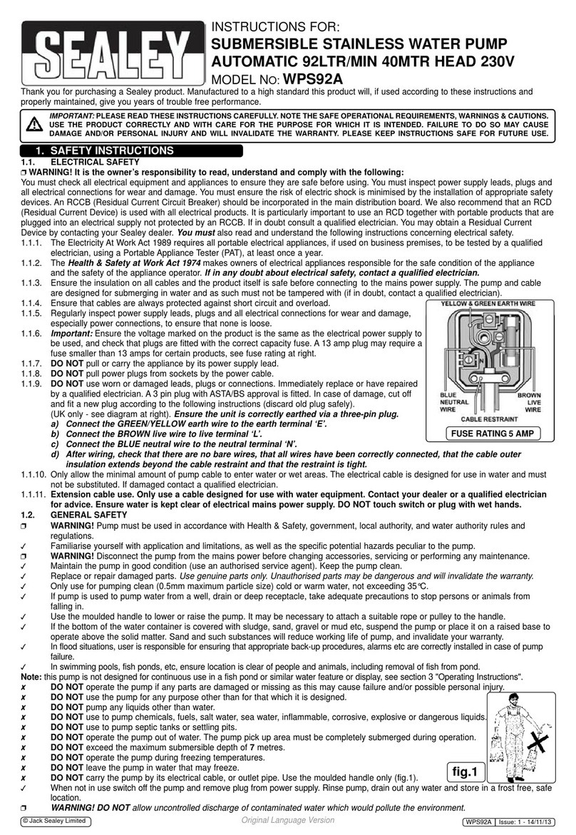
4.1. Mount the baseplate (fig1.1) in a convenient position using suitable fixings (not supplied).
4.2. Fasten the pump assembly to the baseplate using the two hex. bolts supplied (fig.1.2)
4.3. Cut the hose (fig1.3) to the required lengths for the suction and delivery functions.
4.4. Screw a tailpiece (fig.1.4) into the inlet port (marked ‘IN’), using PTFE tape around the thread, and secure the suction hose with a hose
clip (fig.1.5).
4.5. Secure the inlet strainer to the other end of the suction hose with a hose clip (fig.1.6).
4.6. Screw another tailpiece into the delivery port (marked ‘OUT’) again using PTFE tape on the thread, and secure the delivery hose with a
hose clip.
4.7. Secure the remaining tailpiece into the outer end of the delivery hose with a hose clip.
4.8. Attach the delivery nozzle (fig.1.7) to the tailpiece, using PTFE tape as before.
© Jack Sealey Limited Original Language Version TP96.V3, TP9624.V3 Issue: 1 - 20/06/16
g.1
5. OPERATION
NOTE: The suction head (the distance from the pump to lowest liquid level) should not exceed 1 metre, and the delivery tank should be
vented. Install the inlet hose so as the strainer is not less than 25mm from the bottom of the delivery tank.
5.1. Ensure that the switch (fig.1.8) is in the off ( ‘O’ ) position.
5.2. After checking that the battery is of the correct voltage, connect the red clip to the positive (+) battery terminal and the black clip to the
negative (-) terminal.
5.3. Start the pump by switching to the on (I) position. Place the delivery nozzle in the receiving tank and squeeze the trigger to start delivery.
5.4. Release the trigger to stop delivery. DO NOT run the pump for more than 2-3 minutes with the nozzle closed.
5.5. The motor is fitted with a thermal cut-out to prevent overheating. If the unit stops working after an intensive period of use, allow to cool
down thoroughly before re-starting.
6. MAINTENANCE
6.1. An in-line fuse is fitted in the positive cable (fig1.9). To change the fuse: open the fuse holder, remove the blade-type fuse and replace
with one of the same rating.
6.2. Check the tightness of all fittings regularly and tighten if necessary.
6.3. Keep the pump unit and hoses clean to highlight any leaks which may develop in service.
6.4. Remove and clean the inlet strainer regularly.
7. TROUBLESHOOTING
Problem
Possible Cause
Solution
The motor is not running.
Lack of electrical power. Check the electrical connections.
Blown fuse Replace fuse
Rotor jammed. Check for possible damage or obstruction of the
rotating components.
Motor problems. Contact your authorised Sealey dealer.
The motor turns slowly when starting. Power supply is of insufcient voltage. Charge the battery
Low or no ow rate.
Low level in source tank. Rell the tank.
Inlet stainer clogged. Clean strainer.
High inlet vacuum Check tank venting
Air entering the pump or suction tube. Check seals and connections.
Low rotation speed. Check the voltage at the pump.
The suction tubing is resting at the bottom of the
tank. Raise the tubing.
Increased pump noise.
Cavitation occurring. Reduce suction head.
Irregular functioning of the bypass. Dispense fuel until the air is purged from the bypass
system.
Air present in the diesel fuel. Check the suction connections.
Leakage from the body pump. Seal damaged. Contact your authorised Sealey dealer.
© Jack Sealey Limited Original Language Version TP96.V3, TP9624.V3 Issue: 1 - 20/06/16
01284 757500
01284 703534
sales@sealey.co.uk
Sole UK Distributor, Sealey Group,
Kempson Way, Suffolk Business Park,
Bury St. Edmunds, Suffolk,
IP32 7AR
www.sealey.co.uk
NOTE: It is our policy to improve products continually and as such we reserve the right to alter data, specifications and component parts without
prior notice.
IMPORTANT: No liability is accepted for incorrect use of this product.
WARRANTY: Guarantee is 12 months from purchase date, proof of which will be required for any claim.
Environmental Protection
Recycle unwanted materials instead of disposing of them as waste. All tools, accessories and packaging should be sorted, taken to
a recycling centre and disposed of in a manner which is compatible with the environment. When the product becomes completely
unserviceable and requires disposal, drain off any fluids (if applicable) into approved containers and dispose of the product and the
fluids according to local regulations.
Parts support is available for this product. To obtain a parts listing and/or diagram,
please log on to www.sealey.co.uk, email sales@sealey.co.uk or telephone 01284 757500.
© Jack Sealey Limited Original Language Version TP96.V3, TP9624.V3 Issue: 1 - 20/06/16