Boga AIRWIN UB-1 4/3.1 Series User manual

[MBA_UB-1...4_3.1_EN] Rev.: 02/2022 Translation of the original instructions valid from serial number: 4720
No liability accepted for translation or printing errors. Subject to changes in dimensions, weights and other technical data.
All rights reserved. Modifications, reprints and photomechanical reproduction, even in extract from, require the express permission of BOGA GmbH, Werkstraße 16, D-59494 Soest.
Installation and Operating Instructions
AIRWIN®
Ultrasonic Universal Humidifier
UB-1...4/3.1
Type
Item no.
Description
Max. output
UB-1/3.1
7900259
Universal humidifier with 1 active aerosol outlet
0.5 kg/h
UB-2/3.1
7900260
Universal humidifier with 2 active aerosol outlets
1.0 kg/h
UB-3/3.1
7900261
Universal humidifier with 3 active aerosol outlets
1.5 kg/h
UB-4/3.1
7900262
Universal humidifier with 4 active aerosol outlets
2.0 kg/h
Please read and keep these instructions!

2 [MBA_UB-1...4_3.1_EN] Rev.: 02/2022 Translation of the original instructions
No liability accepted for translation or printing errors. Subject to changes in dimensions, weights and other technical data.
All rights reserved. Modifications, reprints and photomechanical reproduction, even in extract from, require the express permission of BOGA GmbH, Werkstraße 16, D-59494 Soest.
Contens
1. General Informations and intended use ............................................................................................................ 4
2. Safety Instructions ............................................................................................................................................. 4
3. Scope of delivery ............................................................................................................................................... 5
4. Optional accessories ......................................................................................................................................... 6
5. General information ........................................................................................................................................... 8
5.1 Technical terms.................................................................................................................................. 8
5.2 Physical principles of piezo ceramics................................................................................................. 8
5.3 Functional description - ultrasonic air humidifier................................................................................ 9
6. Advantages of ultrasonic air humidification..................................................................................................... 10
7. Device overview............................................................................................................................................... 11
7.1 The UB-1…4/3.1-System................................................................................................................. 12
8. Installation conditions ...................................................................................................................................... 13
9. Aerosol distribution systems............................................................................................................................ 14
9.1 Aerosol Jet ....................................................................................................................................... 14
9.2 Aerosol pipes.................................................................................................................................... 15
9.3 Joined aerosol outlets ...................................................................................................................... 15
10. Hydraulic connection ....................................................................................................................................... 16
10.1 Hydraulic conditions......................................................................................................................... 16
10.1 Establishing and detaching the connections with connectors.......................................................... 17
11. Electric connection........................................................................................................................................... 18
11.1 Control connection ........................................................................................................................... 18
11.1.1 Safety chain ...................................................................................................................... 20
11.1.2 Status Message Operation - Error.................................................................................... 20
11.2 Device control................................................................................................................................... 21
11.2.1 Operation control on-off.................................................................................................... 21
11.2.2 Operation control continuous............................................................................................ 21
11.2.3 Control via Modbus RTU................................................................................................... 21
11.2.4 Control via remote control................................................................................................. 21
12. Structure and functions of the control board AIRWIN 3.1 ............................................................................... 22
12.1 Connections ..................................................................................................................................... 22
12.2 Functional description of the controller ............................................................................................ 24
12.3 Standard Settings............................................................................................................................. 25
12.4 Settings ............................................................................................................................................ 26
12.5 State diagram................................................................................................................................... 28
12.6 Status messages.............................................................................................................................. 29
12.7 LED-Indicator and decoding............................................................................................................. 29
12.8 Resetting the maintenance interval.................................................................................................. 30
12.9 Troubleshooting................................................................................................................................ 31
13. AquaDrain plus - hygiene management.......................................................................................................... 32
13.1 Description ....................................................................................................................................... 32

[MBA_UB-1...4_3.1_EN] Rev.: 02/2022 Translation of the original instructions 3
No liability accepted for translation or printing errors. Subject to changes in dimensions, weights and other technical data.
All rights reserved. Modifications, reprints and photomechanical reproduction, even in extract from, require the express permission of BOGA GmbH, Werkstraße 16, D-59494 Soest.
13.2 Features............................................................................................................................................33
13.2.1 Flushing of water supply line .............................................................................................33
13.2.2 Drainage of fluid tank.........................................................................................................35
13.3 AquaDrain plus diagrams..................................................................................................................36
14. Commissioning.................................................................................................................................................37
14.1 Manual functions...............................................................................................................................37
14.2 Automatic functions...........................................................................................................................38
14.3 Make applied settings .......................................................................................................................38
15. Operation..........................................................................................................................................................39
16. Technical data ..................................................................................................................................................40
17. Equipment dimensions / weights......................................................................................................................41
18. Circuit diagrams................................................................................................................................................42
19. Care..................................................................................................................................................................51
20. Standards .........................................................................................................................................................53
20.1 EC declaration of conformity according to Machinery directive 2006/42/EC, Annex II 1.A..............53
20.2 WEEE................................................................................................................................................53
20.3 Legal notice - Copyright....................................................................................................................53
21. List of figures....................................................................................................................................................54
22. List of tables .....................................................................................................................................................54

4 [MBA_UB-1...4_3.1_EN] Rev.: 02/2022 Translation of the original instructions
No liability accepted for translation or printing errors. Subject to changes in dimensions, weights and other technical data.
All rights reserved. Modifications, reprints and photomechanical reproduction, even in extract from, require the express permission of BOGA GmbH, Werkstraße 16, D-59494 Soest.
1. General Informations and intended use
The device is designed for the humidification of demineralised water according to the technical
specifications.
Nebulization of other liquids is not permitted.
These installation and operation instructions apply to all AIRWIN®ultrasonic universal humidifiers of UB-
1…4/3.1 series, hereafter referred to as humidifier. It contains important notes for professional installation,
start-up, trouble-free operation, proper maintenance and cleaning.
In addition to regular maintenance, proper installation and care of the humidifier help to preserve the value of
the humidifier and are conditions for warranty claims.
2. Safety Instructions
The humidifier described in these instructions was developed and manufactured in accordance with
international safety regulations. However, the device must be handled with care, in particular to ensure electric
safety.
In order to guarantee safe operation in all operating conditions, the following safety instructions must be
observed.
•The electrical system may only be set up by qualified electricians.
In this context, the regulations of DIN VDE series 0100 are fundamental.
•The regulations of the local power supplier concerning the electrical connection (e.g.
residual current circuit breaker, additional potential equalisation etc.) must be
complied with. If in doubt, ask your electrician.
•An intended choice of electrical cables and connectors must be used.
•Mains voltage and mains frequency of the voltage supply must correspond to the
parameters indicated on the identification plate of the device.
•Do not connect a damaged device (e.g. damaged during transport) to the mains.
•Contact your customer service, if you have any queries about the electrical
connection, the features or the security of the humidifier.
•Disconnect the device from mains, if it does not work perfectly or if damage
has occurred.
•Disconnect the device from mains, if the electrical supply line is damaged.
•Work on the device may only be carried out as described in these instructions.
•Never use high pressure cleaners to clean the device.
•Use grease and oil-free materials only.

[MBA_UB-1...4_3.1_EN] Rev.: 02/2022 Translation of the original instructions 5
No liability accepted for translation or printing errors. Subject to changes in dimensions, weights and other technical data.
All rights reserved. Modifications, reprints and photomechanical reproduction, even in extract from, require the express permission of BOGA GmbH, Werkstraße 16, D-59494 Soest.
3. Scope of delivery
Universal Humidifier UB-1...4/3.1
Fig. UB-4/3.1
Installation and Spare part list
operating instructions
Water filter for tube connection D/d = 6/4 mm
and Stop cock Ø 6 mm
Item No. 0009178
Discharge tube UB-1...4
(comprising:) tube Ø 12 mm, elbow connection,
T-connector, screw-on connector)
Item No. 0009085
Schuko power cable IEC 2m
Item No. 0001773
SUB-D Connector male, 15-pol, housing
Item No. 0002865

6 [MBA_UB-1...4_3.1_EN] Rev.: 02/2022 Translation of the original instructions
No liability accepted for translation or printing errors. Subject to changes in dimensions, weights and other technical data.
All rights reserved. Modifications, reprints and photomechanical reproduction, even in extract from, require the express permission of BOGA GmbH, Werkstraße 16, D-59494 Soest.
4. Optional accessories
Item no.
Type
Description
Illustration
0009180
Remote Control
Wired remote control, 4-channel,
with lead (2m)
0001144
Tube, PE
D/d=6/4 blue
Tube water supply D=6mm (blue)
0001197
Tube, PE D/d=12/9
black
Tube water drainage D=12mm (black)
6100096
BO-120/1
Room hygrostat for ON/OFF control of the
humidification system, 1-stage
6100097
BO-80
Duct hygrostat for ON/OFF control of the
humidification system
8005062
BO-RO-6/UV-EC
Reverse osmosis system 6 l/h with
permeate storage tank, UV treatment and
U-beam, powder-coated. Other models on
request.
2001130
Leakage tray for
UB-1..4
with flanged sockets, made of V2A stainless
steel with 3D surface (glossy)

[MBA_UB-1...4_3.1_EN] Rev.: 02/2022 Translation of the original instructions 7
No liability accepted for translation or printing errors. Subject to changes in dimensions, weights and other technical data.
All rights reserved. Modifications, reprints and photomechanical reproduction, even in extract from, require the express permission of BOGA GmbH, Werkstraße 16, D-59494 Soest.
Item no.
Type
Description
Illustration
0001327
Aerosol tube
IW = 40 mm, made of PU with plastic spiral,
microbe and hydrolysis resistant,
-30 °C to +90 °C, black
0003503
Hose bracket
for aerosol tube Ø 40 mm
2010005
Aerosol jet 63 NCH
Aerosol distribution pipe 524 mm long
with 12 drill holes
2010004
Aerosol jet 125 NCH
Aerosol distribution pipe 1149 mm long
with 24 drill holes
2001118
Hose adapter 75
screwed to the suction side, Douter = 76 mm,
made of V2A stainless steel, for hose or HT
pipe 75 mm
2001119
Hose adapter 80
screwed to the suction side, Dinner = 80 mm,
made of V2A stainless steel, suitable for
reduction DN 100/80
2001205
Reduction DN 100/80
DN 100/80, galvanised, with seal,
in connection with hose adapter 80
2001206
Aluminium flexpipe
DN 100, compressed approx. 42 cm,
expandable to 10 m
2001201
2001202
Filter box G4
Filter box M6
with connection Ø 100 mm,
filter class ISO coarse 50% (G4)
with connection Ø 100 mm,
filter class ISO ePM10 70% (M6)

8 [MBA_UB-1...4_3.1_EN] Rev.: 02/2022 Translation of the original instructions
No liability accepted for translation or printing errors. Subject to changes in dimensions, weights and other technical data.
All rights reserved. Modifications, reprints and photomechanical reproduction, even in extract from, require the express permission of BOGA GmbH, Werkstraße 16, D-59494 Soest.
5. General information
5.1 Technical terms
Transducer : Piezo ceramic transducer
Aerosols : Finely distributed material (solids or liquids) in air or other gases,
manifestations are e.g.: in smoke, dust, vapour and fog
Demineralised water : Pure water, permeate
Concentrate : Concentrated water, waste water of reverse osmosis system
5.2 Physical principles of piezo ceramics
If certain crystals are deformed by mechanical stress, electrical charges will build up proportionally
on their surface, producing electric field strength in the crystal.
Oscillation line - piezo ceramics
This effect was discovered by Pierre and Jacques Curie
in 1880. Even the reversal of this so-called piezoelectric
effect or piezo-effect is possible. The same materials
change their dimensions under the influence of an
electric field.
Ceramic piezoelectric materials are hard, chemically inactive and completely insensitive to humidity or
other atmospheric influences.
Fig. 1 - Schematic sketch of piezo-effect

[MBA_UB-1...4_3.1_EN] Rev.: 02/2022 Translation of the original instructions 9
No liability accepted for translation or printing errors. Subject to changes in dimensions, weights and other technical data.
All rights reserved. Modifications, reprints and photomechanical reproduction, even in extract from, require the express permission of BOGA GmbH, Werkstraße 16, D-59494 Soest.
Fluid tank
Capillary waves
Ultrasonic transducer
5.3 Functional description - ultrasonic air humidifier
All frequencies above 20,000 Hz are called ultrasonic.
According to their physical nature, acoustic waves consist of mechanical oscillations of compressible
media. These oscillations develop due to the deflection of the particles of a compressible material from
their equilibrium position. Acoustic waves are bound to a medium and thus do not occur in the vacuum.
Oscillations develop as a result of a change in pressure. Repeated pressure increase and pressure
reduction produce different acoustic waves.
In order to be able to use ultrasonic waves for air humidification, electrical energy must be converted
into mechanical energy. This takes place in the piezoelectric transducer.
A vibration unit consists of the resonance circuit where the high frequency of
~ 1.7 MHz is produced and the piezoelectric transducer to convert the electrical frequency into a
proportional mechanical oscillation. This frequency is not audible for human beings or animals.
The piezoceramic transducers are attached
to the bottom of the fluid tank. During
excitation of the transducer, the water leads
the ultrasonic vibrations to the boundary
layer between water and air. Constant
compression and decompression of the
water gauge over the transducer causes
cavitation in the immediate proximity of the
water surface. Thus, crossing capillary
waves are developed, the finest water
particles of which, the aerosols, are
produced in the wave crest.
The aerosols are delivered by the air flow in the humidifier and quickly mix with the ambient air. They
have a small diameter (0.001 - 0.005 mm) and thus form a freely floating mist. The droplet diameter
depends on the surface tension and the density of the medium, but also on the excitation frequency.
The higher the excitation frequency, the smaller is the diameter of the droplets.
Demineralised
water
Point of focusing
Air bubbles
Fig. 2 - Schematic sketch aerosol production

10 [MBA_UB-1...4_3.1_EN] Rev.: 02/2022 Translation of the original instructions
No liability accepted for translation or printing errors. Subject to changes in dimensions, weights and other technical data.
All rights reserved. Modifications, reprints and photomechanical reproduction, even in extract from, require the express permission of BOGA GmbH, Werkstraße 16, D-59494 Soest.
6. Advantages of ultrasonic air humidification
1. maximum energy saving Compared to steam and infrared humidifiers with the same
humidification output, ultrasonic air humidifiers need up to
93 % less electricity.
2. lowest connected load Compared to electrode steam humidifiers with the same
humidification output, only approx. 7 % of the power input
is required. Thus, lower third-party connection costs are
possible.
3. energy-saving cooling effect During humidification with the ultrasonic air humidifiers,
the room air is cooled at the same time due to the adiabatic
humidification principle. The result is a lower heat load
reducing the cooling output requirements.
4. lowest water consumption Nebulizer humidifiers lose up to 70 % of the water, steam
humidifiers up to 30 %. AIRWIN® Ultrasonic air humidifiers
do not have any water loss apart from the cyclical
emptying process of the fluid tank on AquaDrain plus.
5. immediate max. humidification Simultaneously with the request impulse, humidification
is carried out without any delay.
Exception: during automatic drainage and line flushing.
6. max. evaporation of the water Ultrasonic air humidifiers produce a very fine aerosol mist.
On average, the diameter of the aerosols is only 0.001 -
0.005 mm. Thus, the mist spreads quickly and is taken up
by the air after a very short time

[MBA_UB-1...4_3.1_EN] Rev.: 02/2022 Translation of the original instructions 11
No liability accepted for translation or printing errors. Subject to changes in dimensions, weights and other technical data.
All rights reserved. Modifications, reprints and photomechanical reproduction, even in extract from, require the express permission of BOGA GmbH, Werkstraße 16, D-59494 Soest.
Fig. 3 - UB-4/3.1 Overview
7. Device overview
Interface
control signals
15-poles
ON/OFF switch,
Fuse 2.5 A T
and device connection
Green indicator light:
Lights up when
the humidifier is
switched on
Demineralised water inlet
1 bar < pressure ≤ 4 bar
5 µS/cm < conductivity ≤ 20 µS/cm
Water drainage
Push-in connection Ø 12 mm
Water overflow
Push-in connection Ø 12 mm
Axial fan
120 m³/h
Aerosol outlet pipes
Ø 40 mm
Outlet to the on-site drainage
Push-in connection Ø 12 mm
Stop cock
for Ø 6 mm
Water filter
Screwed connection for Ø 6/4 mm
Interface
Remote control
(optional accessories)
12 [MBA_UB-1...4_3.1_EN] Rev.: 02/2022 Translation of the original instructions
No liability accepted for translation or printing errors. Subject to changes in dimensions, weights and other technical data.
All rights reserved. Modifications, reprints and photomechanical reproduction, even in extract from, require the express permission of BOGA GmbH, Werkstraße 16, D-59494 Soest.
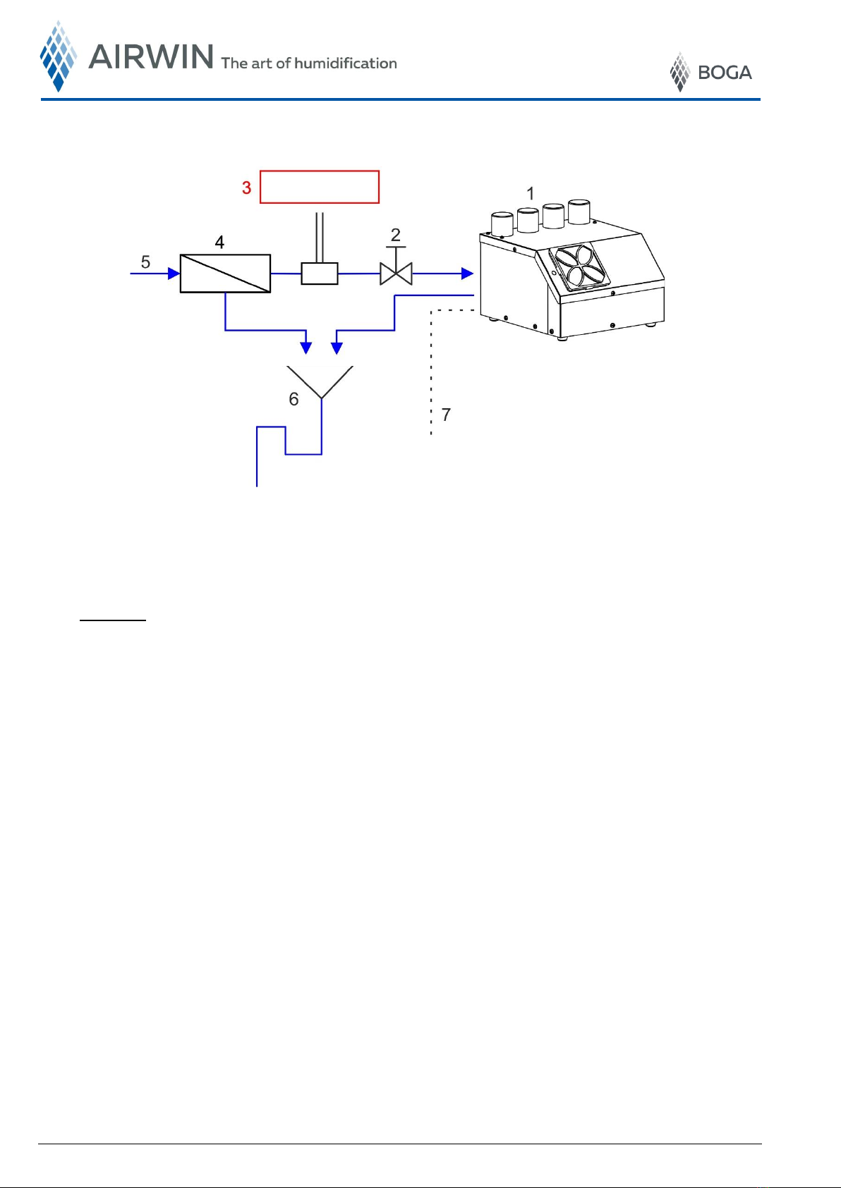
7.1 The UB-1…4/3.1-System
Definitions
1. UB-4/3.1
2. Stop cock (included in the scope of delivery)
3. Conductivity meter to check the quality of the demineralised water
4. Reverse osmosis system (see BOGA product range)
5. Drinking water supply (on site)
6. Free discharge according to DIN 1988-100 (on site)
7. External control (hygrostat or continuous control signal - see BOGA product range)
Fig. 4 - Schematic illustration of UB-4/3.1 humidification system

[MBA_UB-1...4_3.1_EN] Rev.: 02/2022 Translation of the original instructions 13
No liability accepted for translation or printing errors. Subject to changes in dimensions, weights and other technical data.
All rights reserved. Modifications, reprints and photomechanical reproduction, even in extract from, require the express permission of BOGA GmbH, Werkstraße 16, D-59494 Soest.
8. Installation conditions
Correct installation in accordance with the following instructions ensures trouble-free operation of the device.
The device must not be exposed to large temperature differences during installation,
otherwise there is a risk of condensation forming inside the device. This can lead to a failure
of the electronics.
•Visual checks of the device at the installation site should be possible.
•The installation site must allow for simple assembly and disassembly of the device for
maintenance and inspection purposes.
•The device must be installed exactly in the horizontal position to ensure that the water level is the
same above ALL ultrasonic transducers.
•Automatic drainage of the fluid tank and automatic flushing of the demineralised water pipeline
require that a free discharge exists in accordance with DIN 1988-100.
•The humidity sensor must be positioned in such a way that it is located in the area of the
humidifier, but that direct influence by the aerosol flow of air is excluded.
•The stainless steel outlet pipes for the aerosol mist have a diameter of 40 mm and are located so
far away from each other that it is possible to connect commercially HT pipes with integrated lip
seals. The extensive delivery range of HT pipes provides cost-favourable, fast and highly flexible
aerosol guidance; so it is also possible to combine aerosol outputs.
Do not use any greasy lubricants for the installation of the aerosol pipes and tubes, because
that would change the surface tension of the water and nebulisation would no longer be
possible!
The interior areas of the device should always be protected against pollution! (Air filter boxes
see optional accessories)

14 [MBA_UB-1...4_3.1_EN] Rev.: 02/2022 Translation of the original instructions
No liability accepted for translation or printing errors. Subject to changes in dimensions, weights and other technical data.
All rights reserved. Modifications, reprints and photomechanical reproduction, even in extract from, require the express permission of BOGA GmbH, Werkstraße 16, D-59494 Soest.
Fig. 6 - Cross-section of aerosol jet
9. Aerosol distribution systems
Basic conditions:
1. The humidifier must always be operated with an external aerosol distribution system (tube/pipe).
2. Aerosol distribution may not be done in such a way that the device sucks the aerosols in again through
the built-in axial fan and thus works in the aerosol short circuit. As a result, the device could be damaged.
3. For aerosol distribution, all pipes/tubes must be equally long.
9.1 Aerosol Jet
The flexible tubes may be connected to the aerosol jet as shown in Fig. 5 in accordance with variants
a) or b). The optimal solution would be a). In that case, aerosol density is the same along the length
of the aerosol jet whereas in b) the aerosol density decreases nearly linearly towards the end of the
aerosol jet.
Attention:
Aerosol jet holes
are burr-free!
from the
device
The angle between
the aerosol inlet and
outlet must always
be > 90°
Aerosol mist
The aerosol jet must
always be inclined
towards the conden-
sate drain
Condensate drain
to the drainage
Difference in height "h" as low
as possible. The lower "h", the
higher the humidity output at the
openings of the aerosol jet.
Variant a)
Variant b)
Ø 40 mm
> 0°
h
Fig. 5 - Aerosol Jet

[MBA_UB-1...4_3.1_EN] Rev.: 02/2022 Translation of the original instructions 15
No liability accepted for translation or printing errors. Subject to changes in dimensions, weights and other technical data.
All rights reserved. Modifications, reprints and photomechanical reproduction, even in extract from, require the express permission of BOGA GmbH, Werkstraße 16, D-59494 Soest.
9.2 Aerosol pipes
The aerosols may also be distributed without an aerosol jet. The transport of the aerosols is then done
only via pipes or tubes directly to the place of humidification. This place may be in a different room,
even in an aggressive environment.
The pipes or tubes must be placed in such a way that the return of the condensate
is always possible along the entire pipe / tube length. It must be ensured that the
flow resistances of the individual exhaust systems are all the same.
9.3 Joined aerosol outlets
Merging the aerosol outlets may result in a loss of power due to condensation.
Fig. 8 - UB-4/3.1 with joined aerosol outlets
Fig. 7 - UB-4/3.1 with pipes for aerosol transport
Place of humidification

16 [MBA_UB-1...4_3.1_EN] Rev.: 02/2022 Translation of the original instructions
No liability accepted for translation or printing errors. Subject to changes in dimensions, weights and other technical data.
All rights reserved. Modifications, reprints and photomechanical reproduction, even in extract from, require the express permission of BOGA GmbH, Werkstraße 16, D-59494 Soest.
Fig. 9 - Schematic diagram
of hydraulic conditions
10. Hydraulic connection
10.1 Hydraulic conditions
Definitions
1. UB-4/3.1
2. Stop cock (included in the scope of delivery)
3. Demineralised water:
1 bar < pressure ≤ 4 bar
5 µS/cm < conductivity ≤ 20 µS/cm
4. Water demineralisation system (reverse osmosis system)
5. Drinking water supply (on site)
6. Concentrate
7. Water supply for plastic tube Ø 6 mm
8. Water overflow for plastic tube Ø 12 mm
9. Water discharge for plastic tube Ø 12 mm
10. Water overflow hose
11. Free discharge according to DIN 1988-100 (on site)
Important notes:
•The humidifier may be operated with fully demineralised water only (produced for example by a
reverse osmosis system). The demineralised water must have a conductivity of min. 5 µS/cm
and max. 20 µS/cm.
•The contamination of drinking water may not exceed the max. values laid out in the drinking
water regulations.
•The demineralised water is corrosive, therefore use stainless steel or plastic only. Non-ferrous
metals (e.g. copper, brass) must not be used.
•Water pressure must be minimum 1 bar and maximum 4 bar.
•The drainage system on site must be set in accordance with DIN 1988-100.
•The water overflow- and discharge hose must be laid with a constant slope of min. 3% (3 cm on
1 m) to the free discharge.
•For easy revision, the stop cock included in the delivery must be installed in the demineralised
water supply line close to the device.
All materials coming into contact with the demineralised water must be resistant
to demineralised water (observe pressure and temperature resistance).
Demineralised water pipes must be flushed prior to starting the device.

[MBA_UB-1...4_3.1_EN] Rev.: 02/2022 Translation of the original instructions 17
No liability accepted for translation or printing errors. Subject to changes in dimensions, weights and other technical data.
All rights reserved. Modifications, reprints and photomechanical reproduction, even in extract from, require the express permission of BOGA GmbH, Werkstraße 16, D-59494 Soest.
Fig. 10 - Establishing the connection
Fig. 11 - Insert tube
10.1 Establishing and detaching the connections with connectors
The connectors provide durable, safe and watertight connections between tube and connecting
element. The tube is simply inserted by hand. The retaining element holds the tube safely without
pressing it or decreasing the flow.
Establishing the connection
Cut tube squarely and free of burrs.
Make sure that the tube has no sharp edges,
longitudinal grooves or other damage.
Connection is stable prior to sealing
Insert the tube up to the stop.
The supporting element holds the tube in the
connector. With the help of the o-ring,
a tight connection is established.
Check the connection by pulling towards the
opposite side
By pulling towards the opposite side check
whether the tube was safely inserted.
Then slide on the locking ring.
Detaching the connection
First remove the locking ring.
The tube can be detached by pushing back the
supporting element.
All pipes, tubes and connecting elements must be resistant to demineralised
water.
The surface hardness of pipes and tubes must not exceed 225 HV. Otherwise
the retaining teeth in the connector do not securely hold on it.
Soft tubes are also to be avoided.
support element
stainless steel teeth
Fig. 12 - Check connection
Fig. 13 - Detaching the connection
Slide on
locking clip
remove
tube
press back
support element
press back
support element
Remove
locking clip

18 [MBA_UB-1...4_3.1_EN] Rev.: 02/2022 Translation of the original instructions
No liability accepted for translation or printing errors. Subject to changes in dimensions, weights and other technical data.
All rights reserved. Modifications, reprints and photomechanical reproduction, even in extract from, require the express permission of BOGA GmbH, Werkstraße 16, D-59494 Soest.
Fig. 14 - Electric connection
Fig. 15 - 15-pole D-SUB connector
11. Electric connection
The electric connections of the humidifier are found on the side of the housing. Confusion is prevented by
form-coded plugs.
11.1 Control connection
The 15-pole D-SUB connector must be used for the control signals for operating the humidi-fier.
Control signals
see wiring diagram
Power supply
230 V / 50 Hz

[MBA_UB-1...4_3.1_EN] Rev.: 02/2022 Translation of the original instructions 19
No liability accepted for translation or printing errors. Subject to changes in dimensions, weights and other technical data.
All rights reserved. Modifications, reprints and photomechanical reproduction, even in extract from, require the express permission of BOGA GmbH, Werkstraße 16, D-59494 Soest.
Tab. 11-1 - Connection diagram plug D-SUB 15-pin
Clamp
Shortcut
Funktion
Technical description interface
1
SIC
Release
humidification operation
Input for normally control contact
safety chain
2
SIC
Release
humidification operation
Input for normally control contact
safety chain
3
Error
Collective error message
Output potential-free contact
Fault status
4
Error
Collective error message
Output potential-free contact
Fault status
5
Operate
Operational message
Output potential-free contact
Operation status
6
Operate
Operational message
Output potential-free contact
Operation status
7
Hyg 1 (-)
Humidification requirement
50% power
Input for normally control contact
Humidification
8
Hyg 2 (-)
Humidification requirement
100% power
Input for normally control contact
Humidification
9
Hyg (+)
Supply hyg
Common supply hyg
10
Reg-Com
Common
Common ground analog control
11
+Reg-1 mA
Analog input 4...20 mA
Control input 4-20 mA
12
+Reg-2 V
Analog input 0…10 V
Control input 0-10 V
13
RS-485 A
Interface RS-485
RS-485 Modbus A
14
RS-485 B
Interface RS-485
RS-485 Modbus B
15
RS-485 GND
Interface RS-485
RS-485 Modbus Com

20 [MBA_UB-1...4_3.1_EN] Rev.: 02/2022 Translation of the original instructions
No liability accepted for translation or printing errors. Subject to changes in dimensions, weights and other technical data.
All rights reserved. Modifications, reprints and photomechanical reproduction, even in extract from, require the express permission of BOGA GmbH, Werkstraße 16, D-59494 Soest.
Fig. 16 - Safety chain
11.1.1 Safety chain
Connect safety chain on the terminals marked 1 and 2 on the 15-pole plug.
Use potential-free contact.
The input of the safety chain must always be connected to safety devices
with an NC contact.
A cable bridge is always wired at the factory between connections 1-2 /
safety chain.
The humidifier does NOT work otherwise.
If several humidifiers are connected to the safety chain, this must be
isolated and connected to each humidifier with separate switching
contacts.
11.1.2 Status Message Operation - Error
There are two signal outputs via PhotoMOS relay.
Umax : 24 V-DC
Imax : 50 mA
Ron max : 25 Ω
Tab. 11-2 - Status messages operation / error
Status message
Message type
Connection terminal on 15-pole plug
1
Operational message
5 + 6
2
Collective Error message
3 + 4
Fig. 17 - PhotoMOS Relais
B1: limit hygrostat
B2: flow monitor
B3: fan locking
B4: conductivity measurement
B5: ON/OFF switch
This manual suits for next models
8
Table of contents
Other Boga Humidifier manuals


Popular Humidifier manuals by other brands


TaoTronics
TaoTronics TT-AH046 user guide

Trion
Trion HERRMIDIFIER HERRTRONIC MD Series Installation and operation manual

Gorenje
Gorenje ULTRA MYSTIC H50W instruction manual

Holmes
Holmes HCM1100 user manual

Healthy Climate
Healthy Climate HCSteam?16 installation instructions

ElectrIQ
ElectrIQ AC100R user manual