Boga NKBD-6 User manual

[MBA_NKBD_EN] Rev.: 10/2015 8
No liability accepted for translation or printing errors. Subject to changes in dimensions, weights and other technical data.
All rights reserved. Modifications, reprints and photomechanical reproduction, even in extract from, require the express permission of BOGA GmbH, Werkstraße 16, D-59494 Soest.
Installation- and Operation Instructions
NKBD-6, -12, -18, -24, -30, -36, -42
Type
Item No.
Description
Capacity
NKBD-6
7900106
Duct humidifier with 6 outlets
3.6 kg/h
NKBD-12
7900112
Duct humidifier with 12 outlets
7.2 kg/h
NKBD-18
7900118
Duct humidifier with 18 outlets
10.8 kg/h
NKBD-24
7900124
Duct humidifier with 24 outlets
14.4 kg/h
NKBD-30
7910130
Duct humidifier with 30 outlets
18.0 kg/h
NKBD-36
7910136
Duct humidifier with 36 outlets
21.6 kg/h
NKBD-42
7910142
Duct humidifier with 42 outlets
25.2 kg/h
Ultrasonic Duct Humidifier

2 [MBA_NKBD_EN] Rev.: 10/2015
No liability accepted for translation or printing errors. Subject to changes in dimensions, weights and other technical data.
All rights reserved. Modifications, reprints and photomechanical reproduction, even in extract from, require the express permission of BOGA GmbH, Werkstraße 16, D-59494 Soest.
BOGA GmbH • Werkstraße 16 •D-59494 Soest •Fon: +49 2921 96943-0 • Fax: +49 2921 96943-29 • info@airwin.net • www.airwin.net
Contents
1. References ........................................................................................................................................................................................3
2. Safety Instructions....................................................................................................................................................................................3
3. Scope of delivery......................................................................................................................................................................................4
4. Optional accessories................................................................................................................................................................................4
5. General information..................................................................................................................................................................................6
5.1 Technical terms ...........................................................................................................................................................................6
5.2 Physical principles of piezo ceramics...........................................................................................................................................6
5.3 Functional description - ultrasonic air humidifier...........................................................................................................................7
6. Advantages of ultrasonic air humidification...............................................................................................................................................8
7. Equipment overview.................................................................................................................................................................................9
8. The NKBD-System.................................................................................................................................................................................10
9. Installation ......................................................................................................................................................................................11
9.1 Installation conditions –General notes.......................................................................................................................................11
9.2 Installation conditions –special notes ........................................................................................................................................12
9.3 Suction operation.......................................................................................................................................................................14
9.4 Adjustment of the NKBD to the direction of airflow.....................................................................................................................15
10. Hydraulic connection..............................................................................................................................................................................16
10.1Hydraulic conditions...................................................................................................................................................................16
10.2 Establishing and detaching connections with connectors ...........................................................................................................17
11. Electrical Connection..............................................................................................................................................................................18
11.1 Transformer...............................................................................................................................................................................18
11.2 Humidifier ..................................................................................................................................................................................19
11.3 Control and regulation................................................................................................................................................................20
11.3.1 Hygrostat control...........................................................................................................................................................20
11.3.2 Continuous control.........................................................................................................................................................20
11.3.3 Control signal encoding.................................................................................................................................................20
12. AquaDrain - hygiene management.........................................................................................................................................................21
12.1 Description.................................................................................................................................................................................21
12.2 Features ....................................................................................................................................................................................22
12.2.1 Flushing of water supply line..........................................................................................................................................22
12.2.2 Drainage of fluid tank.....................................................................................................................................................24
12.3 AquaDrain diagrams..................................................................................................................................................................25
13. Dimensioning of cable cross section.......................................................................................................................................................26
14. Commissioning ......................................................................................................................................................................................29
15. Technical data ......................................................................................................................................................................................31
16. Device dimensions / weights ..................................................................................................................................................................32
17. Spare parts list ......................................................................................................................................................................................33
17.1 Assembly body duct support.....................................................................................................................................................33
17.2 Assembly fluid tank...................................................................................................................................................................34
17.3 Assembly Control housing.........................................................................................................................................................36
18. Circuit diagrams .....................................................................................................................................................................................38
19. Protection against overvoltage peaks.....................................................................................................................................................50
20. Care ......................................................................................................................................................................................50
20.1 Care plan...................................................................................................................................................................................51
21. Standards ......................................................................................................................................................................................55
21.1 CE Declaration of conformity......................................................................................................................................................55
21.2 RoHS / WEEE............................................................................................................................................................................55
21.3 Legal notice - Copyright.............................................................................................................................................................55
[MBA_NKBD_EN] Rev.: 10/2015 3
No liability accepted for translation or printing errors. Subject to changes in dimensions, weights and other technical data.
All rights reserved. Modifications, reprints and photomechanical reproduction, even in extract from, require the express permission of BOGA GmbH, Werkstraße 16, D-59494 Soest.
BOGA GmbH •Werkstraße 16 •D-59494 Soest •Fon: +49 2921 96943-0 •Fax: +49 2921 96943-29 •info@airwin.net • www.airwin.net
1. References
All AIRWIN®ultrasonic duct humidifiers of NKBD series are designed for installation in supply air ducts and
air conditioning units.
These installation and operation instructions contain important notes for professional installation, start-up,
trouble-free operation and proper maintenance and cleaning.
In addition to regular maintenance, proper installation and care of the NKBD help to preserve the value of the
device and are conditions for warranty claims.
2. Safety Instructions
The humidifier described in these instructions was designed and constructed in accordance with the interna-
tional safety regulations. Like any other electrical device is has to be handled with extreme care, to ensure
safe usage.
In order to guarantee safe operation in all operating conditions, the following safety instructions must be ob-
served.
The electrical system may only be set up by qualified electricians.
In this context, the regulations of DIN VDE series 0100 are fundamental.
The regulations of the local power supplier concerning the electrical connection
(e.g. residual current circuit breaker, additional potential equalisation etc.) must be
complied with. If in doubt, ask your electrician.
An intended choice of electrical cables and connectors must be used.
Mains voltage and mains frequency of the voltage supply must correspond to the
parameters indicated on the identification plate of the humidifier.
Do not connect a damaged humidifier (e.g. damaged during transport) to the
mains.
Contact your customer service if you have any queries about the electrical
connection, the features or the security of the humidifier.
Disconnect the humidifier from mains, if it does not work perfectly or if damage
has occurred.
Disconnect the humidifier from mains, if the electrical supply line is damaged.
Work on the humidifier may only be carried out as described in these instructions.
Never use high pressure cleaners to clean the humidifier.
Use grease and oil-free materials only.

4 [MBA_NKBD_EN] Rev.: 10/2015
No liability accepted for translation or printing errors. Subject to changes in dimensions, weights and other technical data.
All rights reserved. Modifications, reprints and photomechanical reproduction, even in extract from, require the express permission of BOGA GmbH, Werkstraße 16, D-59494 Soest.
BOGA GmbH • Werkstraße 16 •D-59494 Soest •Fon: +49 2921 96943-0 • Fax: +49 2921 96943-29 • info@airwin.net • www.airwin.net
3. Scope of delivery
Duct Humidifier NKBD
Fig.: NKBD-24
Installation and operating instructions
Stop cock Ø 10 mm
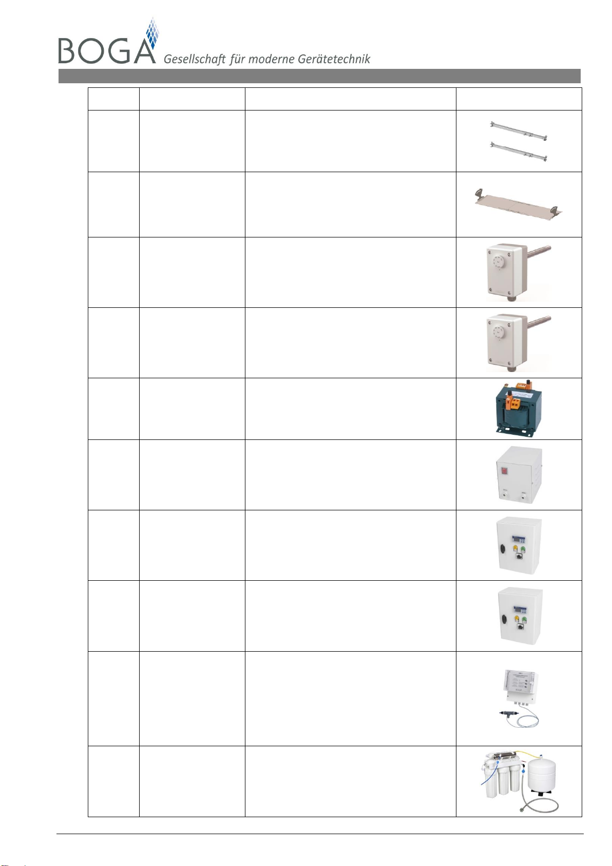
4. Optional accessories
Item no.
Type
Description
Illustration
0001196
Tube, PA
D/d=10/8 mm,
blue
Tube water supply D = 10 mm (blue)
0001847
Tube, PE
D/d=14/11 mm,
nature
Tube water drainage D = 14 mm (nature)
2000105
Mounting brackets
For easy installation of NKBD on a
mounting frame in the air duct, made of
V2A-stainless steel, incl. adjustable foot.
Needs: 2 pcs for NKBD-6 to NKBD-24
3 pcs for NKBD-30 to NKBD-42
200140..
Vertical frame
To build a mounting frame in the air duct,
made of V2A-stainless steel,
height adjustable from 500-700 mm or
700-1200 mm or 1200-2000 mm
PU = 1 set (2 pcs)
[MBA_NKBD_EN] Rev.: 10/2015 5
No liability accepted for translation or printing errors. Subject to changes in dimensions, weights and other technical data.
All rights reserved. Modifications, reprints and photomechanical reproduction, even in extract from, require the express permission of BOGA GmbH, Werkstraße 16, D-59494 Soest.
BOGA GmbH •Werkstraße 16 •D-59494 Soest •Fon: +49 2921 96943-0 •Fax: +49 2921 96943-29 •info@airwin.net • www.airwin.net
Item no.
Type
Description
Illustration
200141..
Telescopic strut
To build a mounting frame in the air duct,
made of V2A-stainless steel,
length adjustable from 500-800 mm or
800-1400 mm or 1400-2000 mm
PU = 1 set (2 pcs)
200130..
Air vortex sheet
To reduce the humidification distance,
made of V2A-stainless steel,
width adjustable from 500-750 mm or
750-1000 mm or 1000-1500 mm or 1500-
2000 mm
6100097
BO-80
Duct hygrostat for ON/OFF control of the
humidification system, 1-step
6100095
BO-80/2
Duct hygrostat for ON/OFF control of the
humidification system, 2-step
77001..
ST200 –ST1600
Transformer for control cabinet
installation, from 200 VA to 1600 VA,
with primary and secondary protection
77002..
STH200 –STH1600
Transformer in powdered steel housing,
with illuminated ON / OFF switch and ca-
ble glands from 200 VA to 1600 VA, with
primary and secondary protection
6002100
SUR/P-4b
Control cabinet with room humidity
sensor or duct humidity sensor for
continuous control
60121..
SUR/PT…
Control cabinet with room humidity
sensor or duct humidity sensor for
continuous control and 500, 1000 or 1600
VA Transformer
8003204
BO-CM-1
Conductivity meter with conductance sen-
sor, cable glands,
conductivity range display,
Conductivity preliminary warning,
conductivity - EMERGENCY/ STOP,
C green : <5 µS/cm
C yellow : 5 µS/cm < C < 20 µS/cm
C red : > 20 µS/cm
8005..
BO-RO-…
Reverse osmosis system 6 l/h and more,
with permeate storage tank,
other models on request
6 [MBA_NKBD_EN] Rev.: 10/2015
No liability accepted for translation or printing errors. Subject to changes in dimensions, weights and other technical data.
All rights reserved. Modifications, reprints and photomechanical reproduction, even in extract from, require the express permission of BOGA GmbH, Werkstraße 16, D-59494 Soest.
BOGA GmbH • Werkstraße 16 •D-59494 Soest •Fon: +49 2921 96943-0 • Fax: +49 2921 96943-29 • info@airwin.net • www.airwin.net
5. General information
5.1 Technical terms
Transducer : Piezo ceramic transducer
Aerosols : Finely distributed material (solids or liquids) in air or other gases,
manifestations are e.g. in smoke, dust, vapour and fog
Demineralised water : Pure water, permeate
Concentrate : Concentrated water, waste water of reverse osmosis system
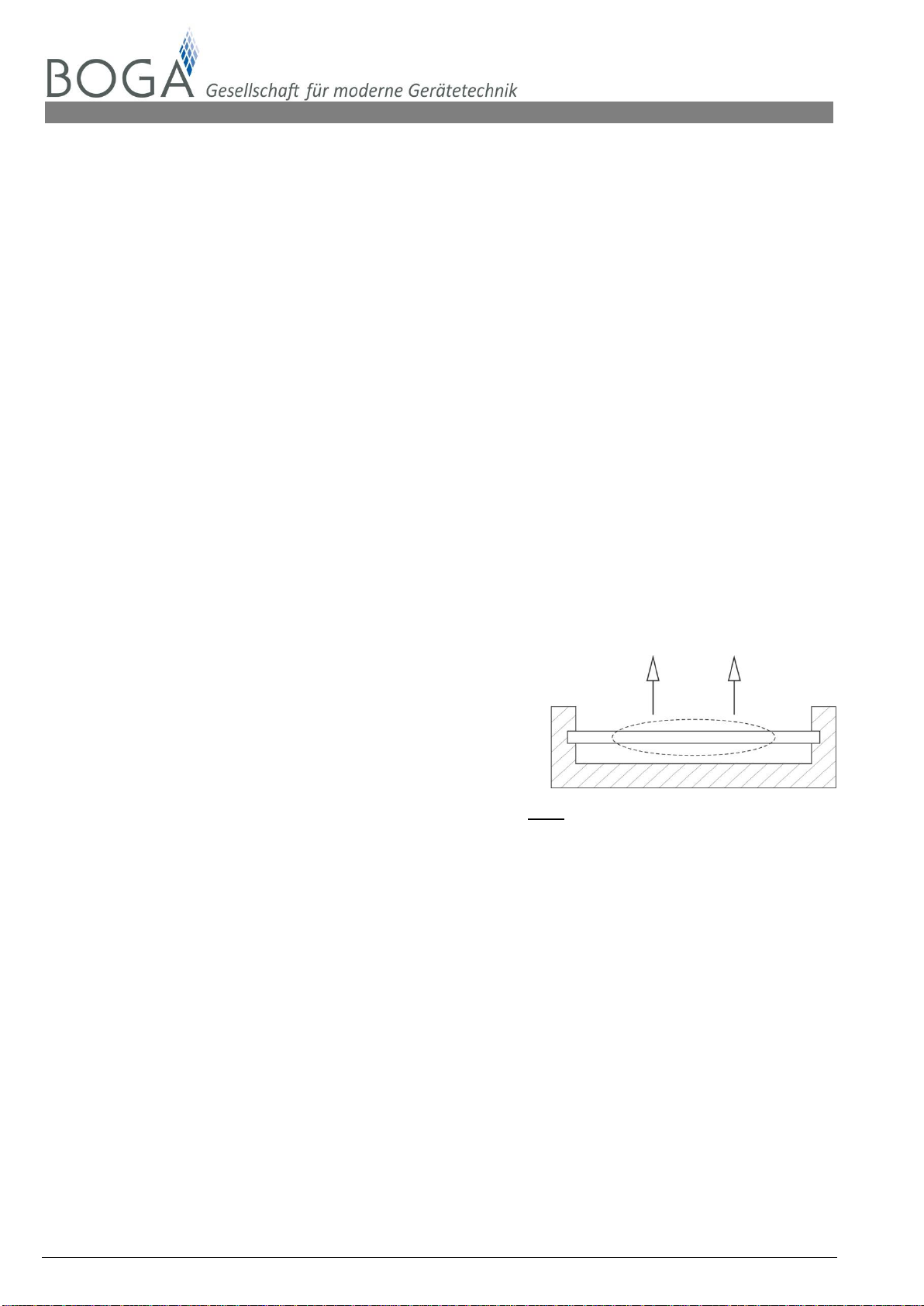
5.2 Physical principles of piezo ceramics
If certain crystals are deformed by mechanical stress, electrical charges will build up proportional-
ly on their surface, producing electric field strength in the crystal.
Oscillation line - piezo ceramics
This effect was discovered by Pierre and Jacques Curie
in 1880. Even the reversal of this so-called piezoelectric
effect or piezo-effect is possible. The same materials
change their dimensions under the influence of an
electric field.
fig. 1 - Schematic sketch of piezo-effect
Ceramic piezoelectric materials are hard, chemically inactive and completely insensitive to humidity
or other atmospheric influences.
[MBA_NKBD_EN] Rev.: 10/2015 7
No liability accepted for translation or printing errors. Subject to changes in dimensions, weights and other technical data.
All rights reserved. Modifications, reprints and photomechanical reproduction, even in extract from, require the express permission of BOGA GmbH, Werkstraße 16, D-59494 Soest.
BOGA GmbH •Werkstraße 16 •D-59494 Soest •Fon: +49 2921 96943-0 •Fax: +49 2921 96943-29 •info@airwin.net • www.airwin.net
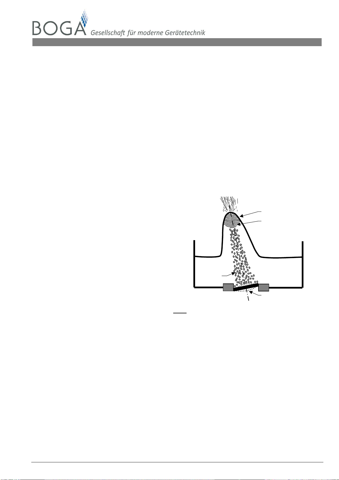
Fluid tank
Capillary waves
Ultrasonic transducer
5.3 Functional description - ultrasonic air humidifier
All frequencies above 20,000 Hz are called ultrasonic.
According to their physical nature, acoustic waves consist of mechanical oscillations of compressible
media. These oscillations develop due to the deflection of the particles of a compressible material from
their equilibrium position. Acoustic waves are bound to a medium and thus do not occur in the vacu-
um.
Oscillations develop as a result of a change in pressure. Repeated pressure increase and pressure
reduction produce different acoustic waves.
In order to be able to use ultrasonic waves for air humidification, electrical energy must be converted
into mechanical energy. This takes place in the piezoelectric transducer.
A vibration unit consists of the resonance circuit where the high frequency of
~ 1.7 MHz is produced and the piezoelectric transducer to convert the electrical frequency into a pro-
portional mechanical oscillation. This frequency is not audible for human beings or animals.
The piezoceramic transducers are attached
to the bottom of the fluid tank. During
excitation of the transducer, the water leads
the ultrasonic vibrations to the boundary
layer between water and air. Constant
compression and decompression of the
water gauge over the transducer causes
cavitation in the immediate proximity of the
water surface. Thus, crossing capillary
waves are developed, the finest water
particles of which, the aerosols, are
produced in the wave crest.
fig. 2 - Schematic sketch aerosol production
The aerosols are delivered by the air flow in the humidifier and quickly mix with the ambient air. They
have a small diameter (0.001 - 0.005 mm) and thus form a freely floating mist. The droplet diameter
depends on the surface tension and the density of the medium, but also on the excitation frequency.
The higher the excitation frequency, the smaller is the diameter of the droplets.
Demineralised
water
Point of focusing
Air bubbles

8 [MBA_NKBD_EN] Rev.: 10/2015
No liability accepted for translation or printing errors. Subject to changes in dimensions, weights and other technical data.
All rights reserved. Modifications, reprints and photomechanical reproduction, even in extract from, require the express permission of BOGA GmbH, Werkstraße 16, D-59494 Soest.
BOGA GmbH • Werkstraße 16 •D-59494 Soest •Fon: +49 2921 96943-0 • Fax: +49 2921 96943-29 • info@airwin.net • www.airwin.net
6. Advantages of ultrasonic air humidification
1. maximum energy saving Compared to steam and infrared humidifiers with the
same humidification output, ultrasonic air humidifiers
need up to 93 % less electricity.
2. lowest connected load Compared to electrode steam humidifiers with the same
humidification output, only approx. 7 % of the power input
is required. Thus, lower third-party connection costs are
possible.
3. energy-saving cooling effect During humidification with the ultrasonic air humidifiers,
the room air is cooled at the same time due to the adia-
batic humidification principle. The result is a lower heat
load reducing the cooling output requirements.
4. lowest water consumption Atomiser humidifiers lose up to 70 % of the water, steam
humidifiers up to 30 %. AIRWIN® ultrasonic air humidifiers
do not have any water loss apart from the cyclical empty-
ing process of the fluid tank on AquaDrain.
5. immediate max. humidification Simultaneously with the request impulse, humidification
is carried out without any delay.
Exception: during automatic drainage and line flushing.
6. max. evaporation of the water Ultrasonic air humidifiers produce a very fine aerosol
mist. On average, the diameter of the aerosols is only
0.001 - 0.005 mm. Thus, the mist spreads quickly and is
taken up by the air after a very short time

[MBA_NKBD_EN] Rev.: 10/2015 9
No liability accepted for translation or printing errors. Subject to changes in dimensions, weights and other technical data.
All rights reserved. Modifications, reprints and photomechanical reproduction, even in extract from, require the express permission of BOGA GmbH, Werkstraße 16, D-59494 Soest.
BOGA GmbH •Werkstraße 16 •D-59494 Soest •Fon: +49 2921 96943-0 •Fax: +49 2921 96943-29 •info@airwin.net • www.airwin.net
7. Equipment overview
fig. 3 - NKBD-24
Input for power supply
48 V / 50 Hz
Input and output for
control signals
Water overflow and drainage
Push-in-connection Ø 14 mm
Demineralised water inlet
Push-in-connection Ø 10 mm
Outlets
Air baffle,
height adjustable

10 [MBA_NKBD_EN] Rev.: 10/2015
No liability accepted for translation or printing errors. Subject to changes in dimensions, weights and other technical data.
All rights reserved. Modifications, reprints and photomechanical reproduction, even in extract from, require the express permission of BOGA GmbH, Werkstraße 16, D-59494 Soest.
BOGA GmbH • Werkstraße 16 •D-59494 Soest •Fon: +49 2921 96943-0 • Fax: +49 2921 96943-29 • info@airwin.net • www.airwin.net
8. The NKBD-System
fig. 4 - Schematic illustration of NKBD air humidification system
Definitions
1. NKBD
2. Stop cock (included in the scope of delivery)
3. External control (hygrostat or continuous control signal - see BOGA product range)
4. Drinking water supply (on site)
5. Free discharge according to DIN 1988 part 4, EN 1717 (on site)
6. Transformer (see BOGA product range)
7. Reverse osmosis system (see BOGA product range)
8. Conductivity meter (e.g. CM-1) to check the quality of the demineralised water
(see optional accessories, BOGA product range)
[MBA_NKBD_EN] Rev.: 10/2015 11
No liability accepted for translation or printing errors. Subject to changes in dimensions, weights and other technical data.
All rights reserved. Modifications, reprints and photomechanical reproduction, even in extract from, require the express permission of BOGA GmbH, Werkstraße 16, D-59494 Soest.
BOGA GmbH •Werkstraße 16 •D-59494 Soest •Fon: +49 2921 96943-0 •Fax: +49 2921 96943-29 •info@airwin.net • www.airwin.net
9. Installation
Proper installation in accordance with the following instructions will ensure trouble-free operation of the
NKBD.
The location of the NKBD installation is predetermined by the requirements of the ventilation system and
should be defined before installation work is commenced.
Protect humidifier interiors necessarily from pollution! The protective foil should only be
removed immediately prior to commissioning when the air ducts have been cleaned!
9.1 Installation conditions –General notes
Installing an insulated tubular lamp in the duct and a window will significantly facilitate visual func-
tion checks on the humidifier.
The place of installation must allow the humidifier to be easily removed and replaced.
The NKBD must be installed in absolutely horizontal position to ensure that ALL the ultrasonic
transducers are covered by the same level of water
The automatic drainage of the fluid tank and the automatic flushing of the pure water line require
a free discharge on site according to DIN 1988 part 4, EN 1717
In the immediate vicinity of the duct humidifier, the ventilation unit should be of waterproof design
(stainless steel or with corrosion-proof coating) and should be provided with a water discharge
outlet.
The air velocity in the free duct cross section (net area after installation of the humidifiers)
V = 1.0 - 4.0 m/s. In the case of higher air velocities, perforated metal plates should be installed in
the vicinity of the humidifiers.
The distance from the bottom edge of the NKBD to the ceiling of the air duct must be min. 390
mm (fig. 5 and 7).
The distance between the NKBD and the duct/trough base must be min. 100 mm (fig. 5 and 7).
The distance between the NKBD control housing and the duct side wall must be min. 70 mm
(fig. 6 und 8).
The distance between the NKBD and the duct side wall must be min. 200 mm (fig. 6 and 8).
The distance necessary from fixtures in direction of flow differs widely (aerosol disintegration dis-
tance). It is dependent on air velocity, air temperature, actual and set point humidity and must be
determined at the planning stage.
To achieve the nominal humidification, it is important that the air velocity is in the range
specified. Furthermore, it is very important that the humidifier is installed in an even
laminar air flow. Maybe a perforated plate or a flow straightener is necessary.

12 [MBA_NKBD_EN] Rev.: 10/2015
No liability accepted for translation or printing errors. Subject to changes in dimensions, weights and other technical data.
All rights reserved. Modifications, reprints and photomechanical reproduction, even in extract from, require the express permission of BOGA GmbH, Werkstraße 16, D-59494 Soest.
BOGA GmbH • Werkstraße 16 •D-59494 Soest •Fon: +49 2921 96943-0 • Fax: +49 2921 96943-29 • info@airwin.net • www.airwin.net
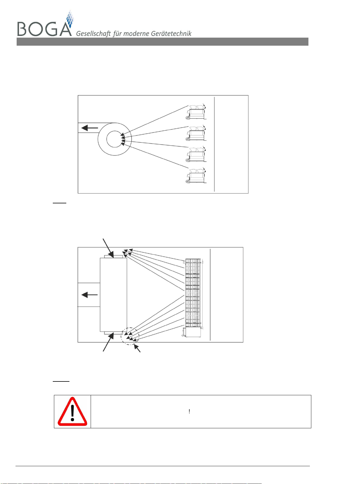
9.2 Installation conditions –special notes
9.2.1 Standard configuration
Mounting example on mounting frame (on site) with mounting bracket NKBD (Item no.
2000105).
fig. 5 - Side view into an air duct with one NKBD
The humidifiers can be arranged directly above one another. The vertical distance between
the humidifiers should be 140 mm.
fig. 6 - View into an air duct in direction of air flow, two NKBD mounted above each
other

[MBA_NKBD_EN] Rev.: 10/2015 13
No liability accepted for translation or printing errors. Subject to changes in dimensions, weights and other technical data.
All rights reserved. Modifications, reprints and photomechanical reproduction, even in extract from, require the express permission of BOGA GmbH, Werkstraße 16, D-59494 Soest.
BOGA GmbH •Werkstraße 16 •D-59494 Soest •Fon: +49 2921 96943-0 •Fax: +49 2921 96943-29 •info@airwin.net • www.airwin.net
9.2.2 Stepped configuration
Humidifiers are mounted above one another; offset horizontally (fig. 7 and 8).
Mounting example on tubular frame (on site) with NKBD mounting brackets (Item No.
2000105).
Stepped configuration is necessary
if the permissible air velocity would be exceeded on standard configuration or
if more humidification is necessary than would be possible with the standard con-
figuration. The minimum vertical distances are smaller than with the standard con-
figuration, which permits installation of more units and thus increased humidifica-
tion.
Requirements:
With stepped configuration, the vertical distance between several humidifiers must
be ≥ 70 mm
The minimum horizontal distance between several humidifiers must be ≥80 mm.
Several humidifiers should be evenly distributed over the entire duct width, observ-
ing the minimum distance of 200/100 mm from the duct walls.
fig. 7 - Side view into an air duct with three NKBD
fig. 8 - View into an air duct in direction of air flow, three NKBD mounted above each
other
14 [MBA_NKBD_EN] Rev.: 10/2015
No liability accepted for translation or printing errors. Subject to changes in dimensions, weights and other technical data.
All rights reserved. Modifications, reprints and photomechanical reproduction, even in extract from, require the express permission of BOGA GmbH, Werkstraße 16, D-59494 Soest.
BOGA GmbH • Werkstraße 16 •D-59494 Soest •Fon: +49 2921 96943-0 • Fax: +49 2921 96943-29 • info@airwin.net • www.airwin.net
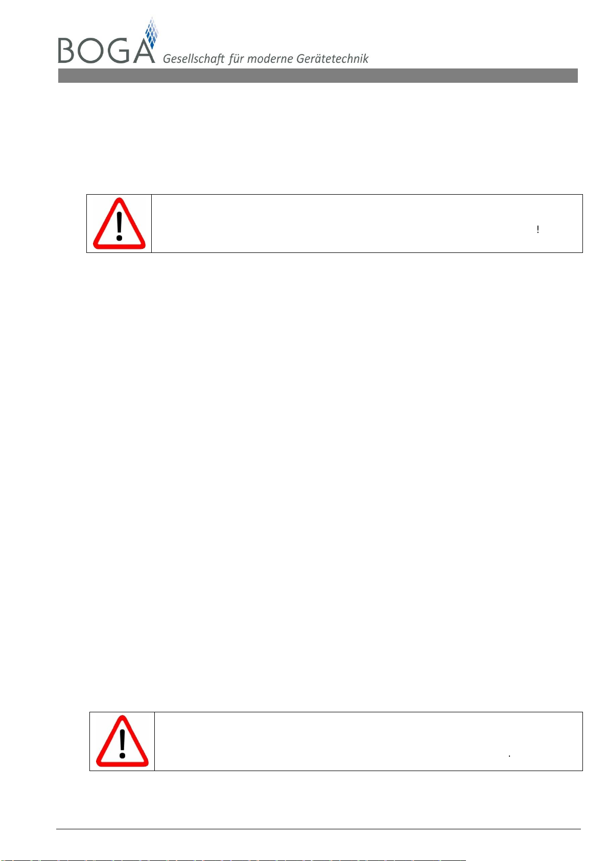
9.3 Suction operation
During suction operation is to ensure that the aerosol mist of the humidifiers is not constricted by the
suction of the fan! As may be the case fit a 50 % perforated plate - consider pressure loss.
Fan
fig. 9 - Side view NKBD in the air duct
Suction opening
Suction opening constriction
fig. 10 - Top view NKBD in the air duct
Avoid constriction of the aerosol mist!
[MBA_NKBD_EN] Rev.: 10/2015 15
No liability accepted for translation or printing errors. Subject to changes in dimensions, weights and other technical data.
All rights reserved. Modifications, reprints and photomechanical reproduction, even in extract from, require the express permission of BOGA GmbH, Werkstraße 16, D-59494 Soest.
BOGA GmbH •Werkstraße 16 •D-59494 Soest •Fon: +49 2921 96943-0 •Fax: +49 2921 96943-29 •info@airwin.net • www.airwin.net
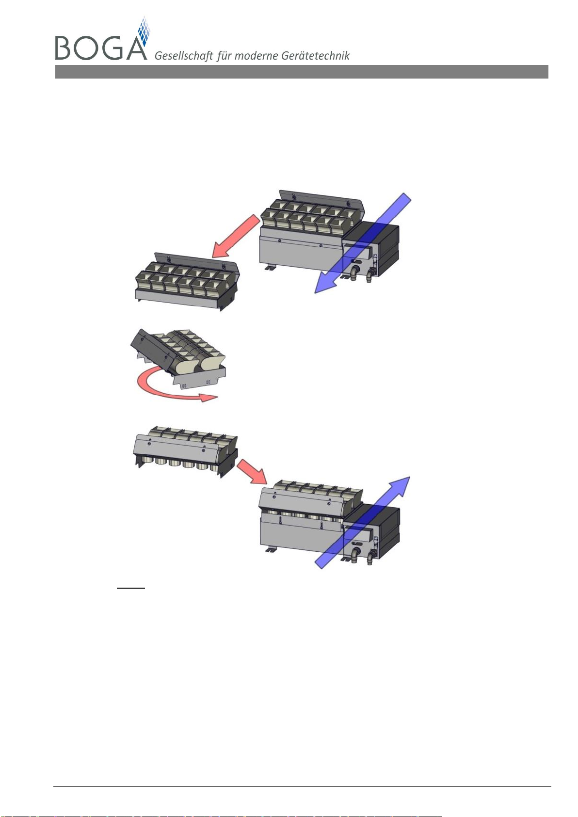
9.4 Adjustment of the NKBD to the direction of airflow
The NKBD can be adjusted to the flow direction of the duct air. Therefore the duct support must
be rotated by 180° if necessary. This allows the humidifier to be situated in a favourable position
for the water and electrical connection.
NKBD direction of the air stream
Body duct support
180°
direction of the air stream
fig. 11 - rotate body duct support
16 [MBA_NKBD_EN] Rev.: 10/2015
No liability accepted for translation or printing errors. Subject to changes in dimensions, weights and other technical data.
All rights reserved. Modifications, reprints and photomechanical reproduction, even in extract from, require the express permission of BOGA GmbH, Werkstraße 16, D-59494 Soest.
BOGA GmbH • Werkstraße 16 •D-59494 Soest •Fon: +49 2921 96943-0 • Fax: +49 2921 96943-29 • info@airwin.net • www.airwin.net
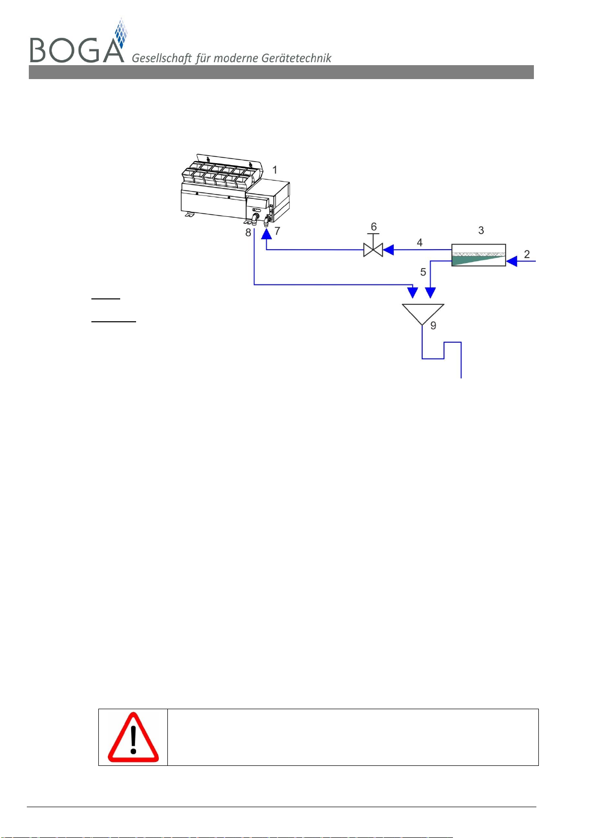
10. Hydraulic connection
10.1 Hydraulic conditions
fig. 12 - Schematic diagram of hydraulic conditions
definitions
1. NKBD
2. Drinking water supply (on site)
3. Water demineralisation system (reverse osmosis system)
4. Demineralised water:
1 bar < pressure ≤ 4 bar
5 µS/cm < conductivity ≤ 20 µS/cm
5. Concentrate
6. Stop cock (included in the scope of delivery)
7. Water supply for plastic tube Ø 10 mm
8. Water overflow and discharge, for plastic tube Ø 14 mm
9. Drainage (on site)
Connections 7-8 are marked with stickers.
Important notes:
The NKBD may be operated with fully demineralised water only (produced for example by a re-
verse osmosis system). The demineralised water must have a conductivity of min. 5 µS/cm and
max. 20 µS/cm.
The contamination of drinking water may not exceed the max. values laid out in the drinking wa-
ter regulations
The demineralised water is corrosive, therefore use stainless steel or plastic only. Non-ferrous
metals (e.g. copper, brass) must not be used.
Water pressure must be minimum 1 bar and maximum 4 bar.
The drainage system on site must be set in accordance with DIN 1988 part of 4, EN 1717.
For easy revision, the stop cock included in the scope of delivery must be installed in the
demineralised water supply line close to the device.
All materials coming into contact with the demineralised water must be resistant
to demineralised water. Observe pressure and temperature resistance.
Demineralised water pipes must be flushed prior to starting the humidifier.
[MBA_NKBD_EN] Rev.: 10/2015 17
No liability accepted for translation or printing errors. Subject to changes in dimensions, weights and other technical data.
All rights reserved. Modifications, reprints and photomechanical reproduction, even in extract from, require the express permission of BOGA GmbH, Werkstraße 16, D-59494 Soest.
BOGA GmbH •Werkstraße 16 •D-59494 Soest •Fon: +49 2921 96943-0 •Fax: +49 2921 96943-29 •info@airwin.net • www.airwin.net
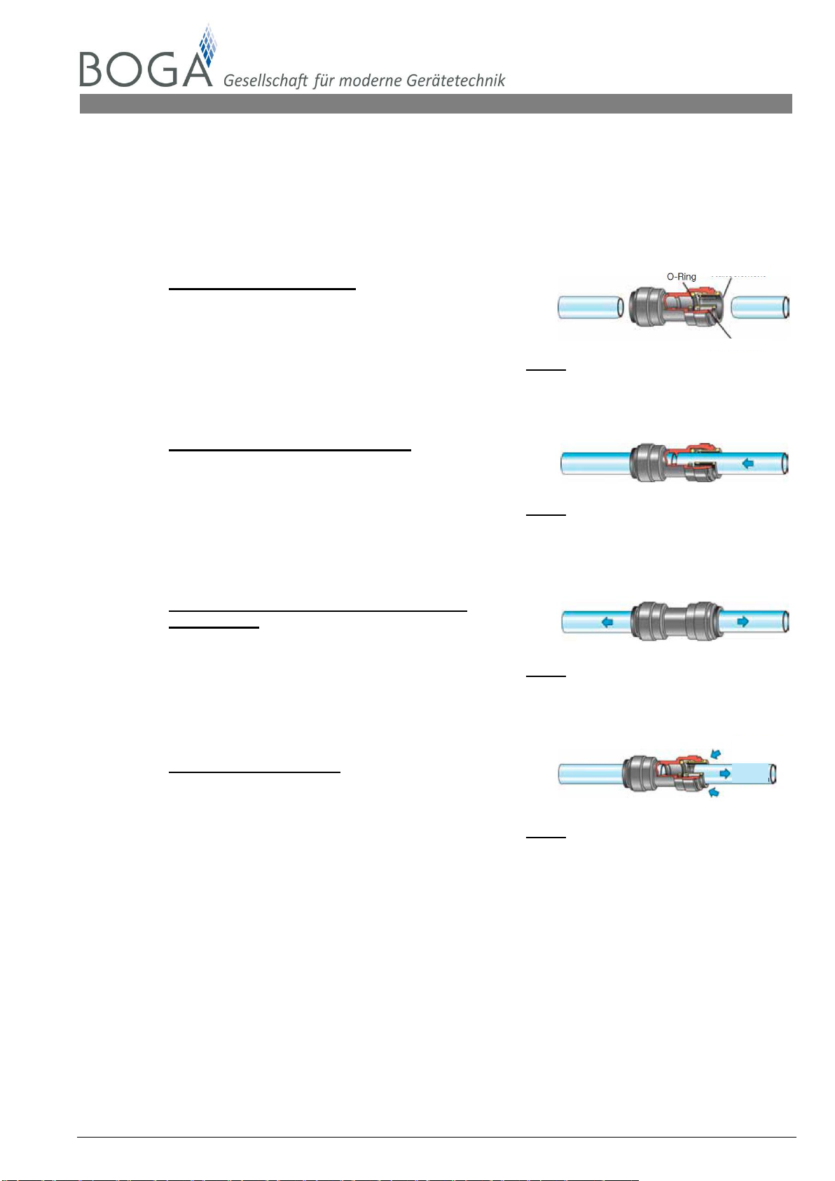
10.2 Establishing and detaching connections with connectors
The connectors provide durable, safe and watertight connections between tube and connecting ele-
ment. The tube is simply inserted by hand. The retaining element holds the tube safely without
pressing it or decreasing the flow.
Establishing the connection
Cut tube squarely and free of burrs.
Make sure that the tube has no sharp edges,
longitudinal grooves or other damage.
fig. 13 - Establishing the connection
Connection is stable prior to sealing
Insert the tube up to the stop.
The supporting element holds the tube in the
connector. With the help of the O-ring,
a tight connection is established. fig. 14 - Insert tube
Check the connection by pulling towards the
opposite side
By pulling towards the opposite side check
whether the tube was safely inserted.
fig. 15 - Check connection
Detaching the connection
The tube can be detached by pushing back the
supporting element.
fig. 16 - Detaching the connection
remove
tube
press back
support element
press back
support element
support element
stainless steel teeth
18 [MBA_NKBD_EN] Rev.: 10/2015
No liability accepted for translation or printing errors. Subject to changes in dimensions, weights and other technical data.
All rights reserved. Modifications, reprints and photomechanical reproduction, even in extract from, require the express permission of BOGA GmbH, Werkstraße 16, D-59494 Soest.
BOGA GmbH • Werkstraße 16 •D-59494 Soest •Fon: +49 2921 96943-0 • Fax: +49 2921 96943-29 • info@airwin.net • www.airwin.net
11. Electrical Connection
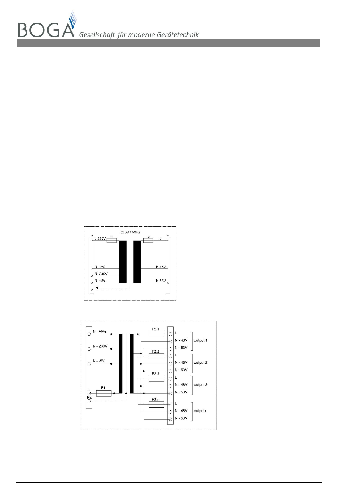
11.1 Transformer
11.1.1 The transformers are available either loose or installed in a sheet metal housing. When in-
stalling in the control cabinet, it is essential to make allowance for the heat dissipated from
the transformers. The control cabinet may have to be provided with forced-air cooling.
11.1.2 A single large transformer may be selected to serve several humidifiers. In such cases,
make sure that each outgoing secondary circuit is fuse-protected, either external in the
control cabinet or within the transformer ex- factory.
11.1.3 The transformer transforms the primary voltage of 230 V / 50 Hz to the secondary voltage
of 48 / 53 V.
11.1.4 The power connection cable leading to the transformer and from the transformer to the
humidifier must at least satisfy H05VV or H05RR specifications.
11.1.5 The transformers of BOGA are manufactured according to the following specifications:
Single-phase control-power transformer in accordance with VDE 0550 Parts 1+3 and VDE
0113, IP00, Protection Class 1, Insulation Class T40E, separate windings, screw-
connection in accordance with VBG4, 50/60 Hz.
fig. 17 - Transformer with a secondary output
fig. 18 - Transformer with multiple secondary outputs
[MBA_NKBD_EN] Rev.: 10/2015 19
No liability accepted for translation or printing errors. Subject to changes in dimensions, weights and other technical data.
All rights reserved. Modifications, reprints and photomechanical reproduction, even in extract from, require the express permission of BOGA GmbH, Werkstraße 16, D-59494 Soest.
BOGA GmbH •Werkstraße 16 •D-59494 Soest •Fon: +49 2921 96943-0 •Fax: +49 2921 96943-29 •info@airwin.net • www.airwin.net
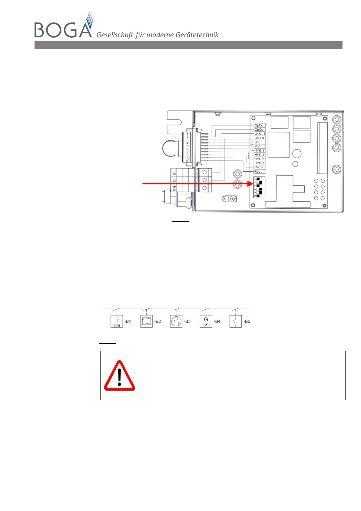
11.2 Humidifier
The humidifier is connected at the 48 V (L, N, PE) bushing terminals for electrical power and at the
10-pole connector (located in the centre section of the control housing) for control/safety
chain/function control. The connections will be exposed by releasing the toggle fasteners on the con-
trol housing cover and removing the cover.
1-2 Function control
3-4 Safety chain
5-6 Hygrostat 50 % *
7-8 Hygrostat 100 % *
9-10 Control signal
DIP-Switch
*of nominal humidifying capacity fig. 19 - Electrical power connection
11.2.1 Humidifier power connection
Connect power (L 48 V - N ) to the appropriately marked bushing terminals
Connect protective earth conductor to the green/yellow bushing terminal
11.2.2 Safety chain
Connect safety chain to the screw-type connectors marked 3and 4.
Observe the 48 VAC power supply.
B1: limit hygrostat
B2: flow monitor
B3: fan locking
B4: conductivity measurement
B5: ON/OFF switch
fig. 20 - Safety chain
The input of the safety chain must always be supplied with a voltage of
48 V. Cable bridges are always mounted ex-factory between connections
1-2 safety chain and 9-10 48 V.
The humidifier does NOT work otherwise.
When connecting several humidifiers, the safety chain must be connected
in parallel to each humidifier.
CAUTION: the 48 V supply must only be taken once.
11.2.3 Operation Control
As soon as the humidifier starts humidifying a relay will close on the control circuit board of
the NKBD. This information may be used for further processing (e.g. building services
management system). Connection at 1 and 2 on the screw-type connector
Load rating of potential-free output: 120 VAC 6 A
48 VAC 6 A
28 VDC 6 A
20 [MBA_NKBD_EN] Rev.: 10/2015
No liability accepted for translation or printing errors. Subject to changes in dimensions, weights and other technical data.
All rights reserved. Modifications, reprints and photomechanical reproduction, even in extract from, require the express permission of BOGA GmbH, Werkstraße 16, D-59494 Soest.
BOGA GmbH • Werkstraße 16 •D-59494 Soest •Fon: +49 2921 96943-0 • Fax: +49 2921 96943-29 • info@airwin.net • www.airwin.net
11.3 Control and regulation
If a hygrostat and continuous controller are connected at the same time, the hu-
midifier always runs first the larger request.
11.3.1 Hygrostat control
HYG 1: 50 % of nominal humidifying capacity - connection 3 and 4
HYG 2: 100 % of nominal humidifying capacity - connection 5 and 6
When connecting several NKBD humidifiers to one hygrostat, they must
be connected in parallel; see circuit diagram (see chapter 18).
11.3.2 Continuous control
The NKBD is capable of processing 10 different external controlled variables (Tab. 11.1).
Coding is shown on the circuit diagrams, including load.
The control cable must be connected at 9(+) and 10(-) paying attention to correct phase
sequence (+/-). From the factory, the control variable 0-10 VDC is always coded.
The connection of the continuous control is shown in the circuit diagrams in Chapter 18.
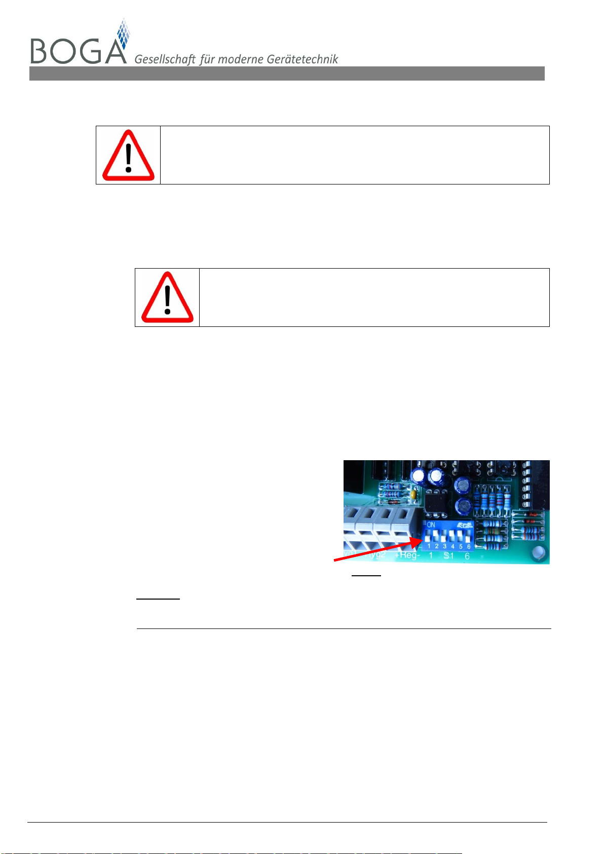
11.3.3 Control signal encoding
The encoding of the input variables below
usually carried out by the 6-pin DIP-switch
S1 on the control board.
DIP-
switch
fig. 21 - control board
Tab. 11.1 Coding table for DIP-switch
Control
1
2
3
4
5
6
Load
input resistance
0 - 20 mA
on
on
-
on
-
-
110.0 mW
275 Ω
4 - 20 mA
on
-
on
on
-
-
110.0 mW
275 Ω
0 - 5 VDC
-
on
-
on
-
-
7.3 mW
3425 Ω
1 - 5 VDC
-
-
on
on
-
-
8.0 mW
3125 Ω
0 - 10 VDC
-
on
-
on
on
-
30.0 mW
3333 Ω
2 - 10 VDC
-
-
-
-
on
-
30.0 mW
3333 Ω
0 - 16 VDC
-
on
-
-
-
on
77.0 mW
3325 Ω
3 - 16 VDC
-
-
on
on
-
on
77.0 mW
3325 Ω
0 - 20 VDC
-
on
-
-
on
on
140.0 mW
2857 Ω
4 - 20 VDC
-
-
on
on
on
on
130.0 mW
3077 Ω
Hyg 1/2
-
-
-
-
-
-
This manual suits for next models
6
Table of contents
Other Boga Humidifier manuals


