Healthy Climate HCSteam?16 User manual

05/12 506746−01
*2P0512* *P506746-01*
Page 1
THIS MANUAL MUST BE LEFT WITH THE
HOMEOWNER FOR FUTURE REFERENCE
Shipping and Packing List
Items shipped
Model HCSteam−16(Cat. No. Y3478) Duct steam injec-
tion, 16 gallons per day (5.5 Lbs per hour) 110−120 VAC.
Model HCSteam−35(Cat. No. Y3479) Duct steam
injection, 35 gallons per day (12 Lbs per hour) 220−240
VAC.
Humidifier installation parts10 ft. steam hose, steam
hose adapter, steam nozzle, water fill hose, condensate
hose, mounting template, installation instructions, product
warranty, steam hose clamps (2), condensate hose clamp.
Air proving switch kit (Cat. no. Y3786)includes 6’ tubing,
switch installation sheet, two ductwork pressure tube taps,
mounting screws and anchors.
Other required items
1/2" water line
25 Amp dedicated electrical circuit
1−1/4" extension tube (can be plumbed into a open drain or
water drain receiver or a condensate pump that can hold 1
gallon of 140º F water then plumbed into a 3/4" drain line)
Before beginning installation
Check for shipping damage to cartons. Mark the shipping
waybill accordingly.
Open cartons and check equipment for shipping damage
or missing components; if found, immediately report any
discrepancies to the last carrier.
INSTALLATION
INSTRUCTIONS
HCSteam−16/−35 Residential
Healthy Climate®Steam
Humidifier
INDOOR AIR QUALITY
506746−01
05/12
Supersedes 01/12
Table of Contents
Shipping and Packing List 1. . . . . . . . . . . . . . . . . . . . . .
Clearances, Unit Dimensions, and
Component/Feature Specifications 2. . . . . . . . . . . . .
General 2. . . . . . . . . . . . . . . . . . . . . . . . . . . . . . . . . . . . . .
Basic humidifier operation 3. . . . . . . . . . . . . . . . . . . . . .
Installation 4. . . . . . . . . . . . . . . . . . . . . . . . . . . . . . . . . . . .
Plumbing 6. . . . . . . . . . . . . . . . . . . . . . . . . . . . . . . . . . . . .
Steam Distribution 8. . . . . . . . . . . . . . . . . . . . . . . . . . . . .
Wiring 10. . . . . . . . . . . . . . . . . . . . . . . . . . . . . . . . . . . . . . .
Start up / Start up checklist 16. . . . . . . . . . . . . . . . . . . . .
Controller 16. . . . . . . . . . . . . . . . . . . . . . . . . . . . . . . . . . . .
Starting the humidifier 16. . . . . . . . . . . . . . . . . . . . . . . . . .
Starting with a new cylinder 16. . . . . . . . . . . . . . . . . . . . .
Operating the humidifier 17. . . . . . . . . . . . . . . . . . . . . . . .
Displaying humidifier information 17. . . . . . . . . . . . . . . .
Changing the maximum production percentage 17. . . .
Activating manual drain 17. . . . . . . . . . . . . . . . . . . . . . . .
Resetting the hour counter 17. . . . . . . . . . . . . . . . . . . . . .
Alarms 19. . . . . . . . . . . . . . . . . . . . . . . . . . . . . . . . . . . . . . .
Troubleshooting 20. . . . . . . . . . . . . . . . . . . . . . . . . . . . . . .
Maintenance 21. . . . . . . . . . . . . . . . . . . . . . . . . . . . . . . . . .
Periodic checks 21. . . . . . . . . . . . . . . . . . . . . . . . . . . . . . .
Cylinder maintenance 21. . . . . . . . . . . . . . . . . . . . . . . . . .
Replacement parts 23. . . . . . . . . . . . . . . . . . . . . . . . . . . .
Technical specifications 23. . . . . . . . . . . . . . . . . . . . . . . .
NOTICE
The humidifier must be installed in accordance with
all local and national standards.
Installation, adjustments, alterations, service and
maintenance must be performed by a qualified ser-
vice technician.
WARNING
Before installing or handling the humidifier, please
carefully read and follow the instructions and safety
standards described in this manual and on the la-
bels attached to the HCSteam−16/−35 Residential
Steam Humidifier.

Page 2
506746−01 05/12
Table 1. Clearances, Unit Dimensions, and Component/Feature Specifications
in. (mm) Lbs. (kg)
A13−1/2 (343) 16 (8)
B8−1/8 (206) 22 (10)
C23−3/4 (603) 26 (12)
in. (mm)
A6 (150)
B6 (150)
C6 (150)
D6 (150)
E24 (600)
Fmax. 0.2º
angle
Clearances Unit Dimensions
AB
C
A
B
C
D
E
F
Component/Feature Nominal Specifications/Range Tolerance
Steam capacity (HCSteam−35) 12 lb/h (5.4 kg/h) −15% +10%
Steam capacity (HCSteam−16) 5−1/2 lb/h (2.5 kg/h) −15% +10%
Water supply pressure limits 15 psi to 116 psi (0.1 to 0.8 MPa) −− −−
Water supply temperature limits 34°F to 104°F (1°C to 40°C) −− −−
Water supply flow minimum 0.12 gpm (0.45 L/min) −− −−
Power supply (HCSteam−35) 220−240 VAC −15% +10%
Power supply (HCSteam−16) 110−120 VAC −15% +10%
Total Drain Water Flow 7 gpm (26.2 L/min) −10% +10%
Ambient temperature operating 34°F to 104°F (1°C to 40°C) −− −−
Ambient humidity operating 10 to 60% rH −− −−
Ambient temperature storage 14°F to 158°F (−10°C to 70°C) −− −−
Ambient humidity storage 5 to 95% rH −− −−
General
The HCSteam−16/−35 humidifier produces non−pressur-
ized steam which is then used to humidify the air.
The quality of the water used affects the operation of this
unit, so the humidifier may be supplied with untreated wa-
ter, as long as it is drinkable and not softened or demineral-
ized. The water converted into steam is automatically re-
placed through an electric fill valve. Periodically, based on
the water quality, the unit will also drain some water to di-
lute the build−up of minerals in the steam generator.
This humidifier has been designed to directly humidify
ducts using a distribution system. The installation, use and
maintenance operations must be carried out according to
the instructions contained in this manual and on the labels
applied internally and externally.
Disconnect the humidifier from the main power supply be-
fore accessing any internal parts.
The conditions of the environment and the power supply
voltage must comply with the specified values listed on the
data label in the humidifier.
All other uses and modifications made to the humidifier
that are not authorized by Lennox are considered unautho-
rized, and Lennox assumes no liability for the conse-
quences of any such unauthorized use.
Please note that the humidifier contains powered electrical
devices and hot surfaces.
NOTICE
The humidifier requires water to operate.
Do NOT mount it above materials or machinery that
could be damaged if a leak occurs. Lennox assumes
no responsibility for consequential or inconse-
quential damage as a result of any leaks.
If unit must be located where any leaking water
could cause damage, an auxiliary drain pan is rec-
ommended.
Disposal of humidifier parts
The humidifier is made up of metallic and plastic parts. All
parts must be disposed of according to the local standards
on waste disposal.

Page 3 HCSTEAM−16/−35 SERIES
Basic Humidifier Operation
STEAM
CYLINDER
FILL CUP
USER INTERFACE / DISPLAY
ON / OFF & SET BUTTONS
DRAIN PUMP
FILL VALVE
DRAIN TANK
TEMPERING VALVE
STEAM HOSE ADAPTER
WATER
INLET AND
FILTER
Figure 1. Basic humidifier components
CAUTION
SCALDING HAZARD!
The humidifier has heated parts (1005C/ 2125F).
The HCSteam−16/−35 is an electrode humidifier. It produces
steam for humidification by passing electric current through
metal electrodes (7, figure 2) immersed in water inside a
plastic steam cylinder (5). There are no heating elements.
Steam output is directly proportional to the conductivity of the
water, and the amount of electrode immersed in the water.
On a call for humidity, the HCSteam−16/−35 humidifier con-
troller opens the water fill valve (1) and allows water to en-
ter the cylinder. A flow restrictor (4) prevents the unit from
filling too quickly or with too much pressure. The water
flows up the fill tube (2) and into the fill cup (3).Water then
flows over the dam in the fill cup (3), creating a 1" air gap
that prevents contaminated water backflow into feed lines.
Water then flows through the fill tube (6) and into the bot-
tom of the steam cylinder (5). Any backflow or overflow of
water travels through the overflow hose (13) to the drain.
HL
DT
13
OVERFLOW
HOSE
2
FILL TUBE
6
FILL TUBE
3
FILL CUP
4
FLOW
RESTRICTOR
1
FILL VALVE
11
DRAIN
PUMP
10
TEMPERING
VALVE
CYLINDER
FULL PROBE
9
STEAM
OUTLET
8
ELECTRODE
7
STEAM
CYLINDER
5
STRAINER
12
Figure 2. Basic humidifier operation
As the water fills the cylinder, it will reach the electrodes (7)
and current will begin to flow. As the water continues to fill
the cylinder, the current will increase, and this is monitored
by an amperage transformer connected to one of the pow-
er wires and located on the electronic controller. When the

Page 4
506746−01 05/12
desired current is reached, the fill valve (1) will close and
the water will then begin to warm and produce steam. If the
water reaches the cylinder full probe (9) or if current rises
too much, the drain pump (11) will be activated to drain
away some water and reduce the current flow to accept-
able levels. Note that, any time the drain pump is activated,
the tempering valve (10) will be opened for tempering the
hot drained water down to 140º F (60ºC) in accordance to
local and national standards.
Periodically, based on the incoming water conductivity, the
unit will run drain pump (11) and drain some water to re-
duce the mineral concentration. A strainer (12) in the cylin-
der helps to prevent mineral debris from jamming the drain
pump (11).
In case the HCSteam−16/−35 humidifier remains powered
but idle, i.e. without producing steam, for more than 48
hours (2 days), the cylinder will be emptied to not have
stagnant water inside.
If there is no water in the cylinder, there will be no current
flow and no steam production. The electrodes do not burn
out, but they will eventually become completely coated
with mineral and the cylinder will then need to be replaced.
Cleaning cylinders may cause electrode damage, there-
fore voiding its warranty. See maintenance section on
Page 21.
Installation
Installing the nozzle
The HCSteam−16/−35 humidifier’s nozzle must be installed
onto the ductwork near the humidifier. Refer to the Steam
Distribution section (Page 8) for information on how to
properly locate the nozzle, for dimensions for the hole
mounting pattern, and for connections to the humidifier
and to the condensate drain. (Also see figure 6 for a typical
installation diagram.)
Drill a 2−1/4" (57 mm) hole in the ductwork at the selected
location for inserting the nozzle into the duct work. Position
the nozzle in the hole. Mark and drill 1/16" mounting holes
and use self−tapping sheet metal screws to attach the
nozzle to the duct.
Removing the humidifier front cover
The front cover is secured by four screws located at the
four corners of the unit. Using a Phillips head screwdriver,
loosen the four cover screws and then pull the front cover
away from the back part of the unit (see figure 3).
Installing the humidifier
CAUTION
Do not install the humidifier in an location that is
within the reach of children.
If unit must be located where any leaking water
could cause damage, an auxiliary drain pan is rec-
ommended.
Do not install humidifier in a location where freezing
temperatures may occur. Water supply and drain
lines may freeze causing water damage.
Positioning the humidifier
The HCSteam−16/−35 humidifier has been designed for
on−wall installation. The simplest and most efficient instal-
lation would have the humidifier installed just below the
duct where the steam nozzle is to be installed. This mini-
mizes steam hose length and the amount of condensate.
Certain clearances must be maintained around the
unit for safety and maintenance (see table 1 on
Page 2)..
If present, remove packing as shown in figure 4.
REMOVE PROTECTIVE
FILM FROM COVER
Figure 3. Removing the front cover
REMOVE PACK-
ING BEFORE
INSTALLING
LATCH THE CYLINDER
CLAMP
REMOVE PACKING
BEFORE INSTALLING
REMOVE
RESTRAINT
BEFORE
INSTALLING
REMOVE PRO-
TECTIVE FILM
FROM DISPLAY
Figure 4. Removing Packing

Page 5 HCSTEAM−16/−35 SERIES
Installing humidifier on a wall
Fastening to the wallDrill mounting holes in the wall using the installation template; then secure the humidifier firmly to
the wall using the supplied screws and anchors (see figure 5).
2−3/8"
(60)
2−3/4
(70)
5
(128)
5
(128)
10−1/8
(257)
2−1/2
(65)
Dimensions in inches (mm)
1−7/8
(48)
2−3/4
(70)
2−1/8
(54)
3/8
(9)
17−5/8
(448)
3−7/8
(98)
1−1/2
(38)
2−3/8
(60)
2−3/8
(60)
23−5/8
(600)
3−5/8
(92)
5/8 (16)
3−1/4
(82)
1−3/8
(35)
2 dia. (51) 7/8 dia. (23)
1−5/8
(40)
7/8
(24)
3−1/8
(78)
1−1/2
(37)
2−1/8
(53)
2
(51)
2−1/2
(62)
1−3/8
(36)
3−7/8
(98)
4
(102)
1−1/8 dia. (30)
1−5/8 dia. (40)
MOUNTING
HOLES
STEAM
CONDENSATE
DRAIN
ELECTRICAL
ELECTRICAL
FILL
FILL
DRAIN
STEAM
CONDENSATE
C L
C L
13−7/16
(341)
8 (204)
Figure 5. Installation dimensions and details

Page 6
506746−01 05/12
Installing the air proving switch (included)
IMPORTANT − Failure to install the air proving switch
will void the humidifier warranty!
The air proving switch (Cat. no. Y3786; provided with hu-
midifier) is a differential pressure switch that is required to
make sure that the blower is running prior to steam produc-
tion. Six feet of 3/16" tubing is provided along with two
pressure taps (mounting screws are not included) to con-
nect both pressure taps to the switch, however, install the
switch first, and then install one pressure tap in only the
supply duct (positive pressure application, step 2. below).
See figure 6.
1. Install switch and pressure tap
Select a mounting location near the supply duct which
will not be subject to vibration or where the switch
could be damaged. Mount the air proving switch in any
vertical plane except with the tubing connections di-
rected upward.
Connect the normally open terminals on the air proving
switch to the low voltage terminal strip in the humidifi-
er. See wiring diagrams in figures 13 through 17.
2. Positive pressure applicationUse the positive
pressure application when large amounts of air flow or
high static is present at the pressure tap in the supply
duct.
Install the duct air sampling tap to the supply duct work
as close to the switch as possible on the positive side
of the blower (see figure 6).
From the 6’ tubing provided, cut just enough 3/16" tub-
ing to reach from the pressure tap to the P1 switch
port. (P2 remains open).
NOTE − Check for closure of the blower switch using
the lowest blower speed setting. If the switch fails to
close the open set of contacts, you must use the differ-
ential application.
3. Differential pressure applicationUse the differen-
tial pressure application when small amounts of air
flow or low static is present across the pressure tap.
Install the 2nd pressure tap in the return duct work (see
figure 6).
Use the remaining 3/16" tubing to connect P2 switch
port to the negative pressure tap. Check for closure of
the switch when blower is turned on.
Plumbing
Water characteristic requirements
The humidifier must be supplied with water with the
following characteristics:
SPressure between 20 psi and 110 psi (0.137 MPa and
0.758 MPa; [1.4 and 7.6 bar])
STemperature between 33º F and 104º F (1ºC and
40ºC)
SFlow−rate minimum of 0.21 gpm (0.45 L/m)
SHardness no greater than 400 ppm3of CaCO (40º fH)
SConductivity from 125 to 1250 μS/cm
SAbsence of organic compounds
SThe characteristics of the water supply must fall within
the following limits:
MPa = Megapascals
fH = French degrees of hardness
μS/cm = microsiemens per centimeter
Unacceptable water types:
SSoftened Wateras this will lead to foam, electrode
corrosion and greatly shortened cylinder life.
SWater containing disinfectants or corrosion inhibiters,
as these are potential irritants.
SIndustrial water, boiler water or water from cooling cir-
cuits.
SAny potentially chemically or bacteriologically
contaminated water.
SHeated water.
Testing Water
A conductivity
meter is
recommended for
testing the water: Cat # Y3480 (AP−2 AquaPro Water
Quality Tester). Specifications:
EC Range: 0−9999 μS.
Temperature Range: 0−80 °C; 32−176 °F.
Resolution: 1 μS; Temp. resolution is 0.1°C/F.
Accuracy: +/− 2%
Calibration: Digital calibration by push button.
Housing: Water−resistant.
Power source: 1 x 3V button cell (included) (model
CR2032).
Dimensions: 15 x 2.8 x 1.3 cm (5.9 x 1.1 x .5 inches) .
Weight: 42.5 g (1.5 oz.).
Water supply connection
The recommended connection between the fill valve and
the water supply line is by way of the provided fill hose (5’
[1.5 m] hose with one straight 3/4" fitting and one 90 de-
gree 3/4" fitting). The provided hose absorbs water "ham-
mering" in order to avoid fill valve damage.
The water line may be routed through the back or through
the bottom of the unit. The fitting then threads onto the
valve assembly inlet located on the bottom of the humidifi-
er (see figure 6) using a 3/4" female garden hose connec-
tion. Note that there is a strainer built into the fill valve fitting
underneath the unit, which will require periodic cleaning,
so be sure to allow clearance for access.

Page 7 HCSTEAM−16/−35 SERIES
SUPPLY
RETURN
STEAM
NOZZLE
STEAM HOSE
STEAM CONDEN-
SATE RETURN LINE
MIN 5º
slope
DRAIN LINE
DETAIL A
DRAIN
LINE
DETAIL A
DRAIN
LINE
WATER FILL HOSE
SHUTOFF VALVE AND
FILTER (Recommended)
SUPPLY
WATER
EXTENSION
TUBE
SHUTOFF VALVE AND
FILTER (Recommended)
OPEN
DRAIN
DRAIN
LINE
Water inlet with filtering
screen (3/4" hose con-
nection)
1−1/4"
Water
drain
STEAM
HOSE
ADAPTER
FILL CUP
FILL
HOSE
OPEN
DRAIN
TO SUPPLY
AIR TAP
TO RETURN
AIR TAP
(if used)
AIR PROVING SWITCH
INSTALL TRAP IN
CONDENSATE LINE
PER FIGURE 9.
SUPPLY
AIR TAP
RETURN
AIR TAP
Figure 6. Typical Installation

Page 8
506746−01 05/12
Water drain
WARNING
The drain pipe must be free without back pressure.
We recommend an external anti−flooding device
(not supplied) to protect from faults of external
hydraulic circuits.
The HCSteam−16/−35 humidifier also requires a connec-
tion to a drain. The drain line may be routed out the back or
bottom of the unit using the included angle fitting. The drain
line can be 1−1/4" PVC, CPVC or polypropylene tubing
(drain line must be able to withstand 140°F water). The
drain line is not glued or otherwise attached to the humidifi-
er so it must be supported by itself. The humidifier includes
a drain tempering valve that runs whenever the drain pump
runs and flushes cool water into the drain line to insure the
drain water temperature never exceeds 140°F (60°C).
The drain water characteristics are:
SDrain Rate 7.1 gal/min. (26.8 lit/min.)
SConnection 1−1/4" (32mm)
STemperature 140°F (60°C)
Drain connections
When using a rear outlet drain passing through drywall, we
suggest using a 1−1/4" extension tube. When using a bot-
tom outlet drain, attach the included 90°fitting to the drain
outlet. The drain outlet may be rotated. Then connect a
1−1/4" trap adaptor to connect to drain pipe.
Steam Distribution
CAUTION
Do not touch steam hose when humidifier is operat-
ing!
The steam hose is a heated part. Allow to cool before
servicing.
Duct steam injection
The maximum allowed duct static pressure is 2" w.c.
The HCSteam−16/−35 humidifier include a plastic injection
nozzle (figure 7).
CONDENSATE
CONNECTION
2−1/2"
(63m)
2−1/2"
(63m)
STEAM
INLET
O.D. − 2.2" (56mm);
drill 2−1/4" (57mm)
hole in duct
Figure 7. Plastic injection nozzle
A typical installation is shown in figure 6.
NOTICE
Nozzle location is very important to the proper ab-
sorption of the steam in the air stream. Select a loca-
tion observing the following:
Snozzle must be installed in supply duct,
Snozzle location must be easily accessible,
Snozzle location must allow at least 3’ (1m) of
straight metal duct without elbows or obstruc-
tions,
Sduct must be un−insulated interior, and if in un-
conditioned spaces, insulated exterior,
Sclearances shown in figure 8 must be maintained.
Installing return condensate hose
The return condensate hose from the nozzle must be
trapped. Coil the hose into a vertical loop and secure it be-
low the nozzle. This trap prevents steam from being re-
leased into the cabinet. The hose end may be run through
the knockout at the top of the humidifier and be inserted
into the hole located on top of the fill cup. See figures 6 and
9.
height
min. 8"
1/3 height
centered
min. 8"
Figure 8. Plastic nozzle installations
Installing steam hoses
NOTICE
Ninety percent (90%) of all operation problems are
created by improper steam piping from the humidifi-
er unit to the duct steam nozzle.
Make the connection between the humidifier steam hose
adapter and nozzle using only the provided hose (unsuit-
able hoses may weaken and crack causing steam leaks).

Page 9 HCSTEAM−16/−35 SERIES
SAvoid the formation of pockets or traps where conden-
sate may form.
SAvoid choking the hose due to tight bends or twisting.
SFasten the end of the hose to the steam hose adapter
on the humidifier and the steam nozzle using metal
hose clamps, so that these do not detach due to the
high temperature.
NOTES −
Slope piping up in direction of steam flow at 20º or greater (2−1/2" per foot [63 mm per 305 mm])
Slope piping down in direction of steam flow at 5º or greater (3/4" per foot [19 mm per 305 mm])
Max. length of rubber steam hose is 10’ (3 m)
TYPICAL INSTALLATION
WHEN UNIT IS ABOVE
THE STEAM NOZZLE
5 ft (1.5 M) MAX. 5 ft (1.5 M) MAX.
IF NO SLOPE
3" (.9M) MAX.
>20º >5º
10 ft (3M) MAX.
5ft (1.5 M) MAX.
>20º >5º
GENTLE
BEND
OBSTRUCTION
SUPPORTED STEAM HOSE
AND/OR COPPER PIPE
DRAINS
P−trap
NOTE − Height of traps must be greater than the
duct static pressure
DRAINS
>20º
>20º
Figure 9. Installing steam hoses
NOTE − Maximum length of rubber steam hose is 10 ft. (3 m). Insulated copper tubing may be up to 20 ft. (6 m) in length. In all
cases, minimize sharp bends and elbows. Use 2 − 45elbows instead of 90 elbows. Hose inner diameter = 7/8" (22 mm);
Hose outer diameter = 1−1/4" (30 mm).
NO DISTRIBUTION
PIPE DRAIN
UN-
DRAINED
ELBOW
NO
SLOPE
UN-
DRAINED
ELBOW
SAG
NO TRAP
NO SLOPE
KINKED
Figure 10. Unacceptable examples of installing steam hoses
Page 10
506746−01 05/12
Wiring
Power wiring
All wiring must be in accordance with local, state and national electric codes.
Model
Power supply
(single phase)
Steam Output
lbs/hr (kg/h) kW Amps
External Power
Wire Gauge
External Fuse (A)
or Breaker
HCSteam−16 110−120 VAC 50/60Hz 5.5 (2.5) 1.80 16.40 AWG10 25
HCSteam−35 220−240 VAC 50/60Hz 12 (5.4) 3.89 16.95 AWG10 25
WARNING
ELECTRIC SHOCK HAZARD!
The humidifier uses electrical power.
Always disconnect the main power before opening
or servicing the humidifier!
NOTE − To avoid unwanted interference, the power cables
should be kept separate from any control wiring.
NOTE − Tolerance allowed on main voltage =−15% to
+10%.
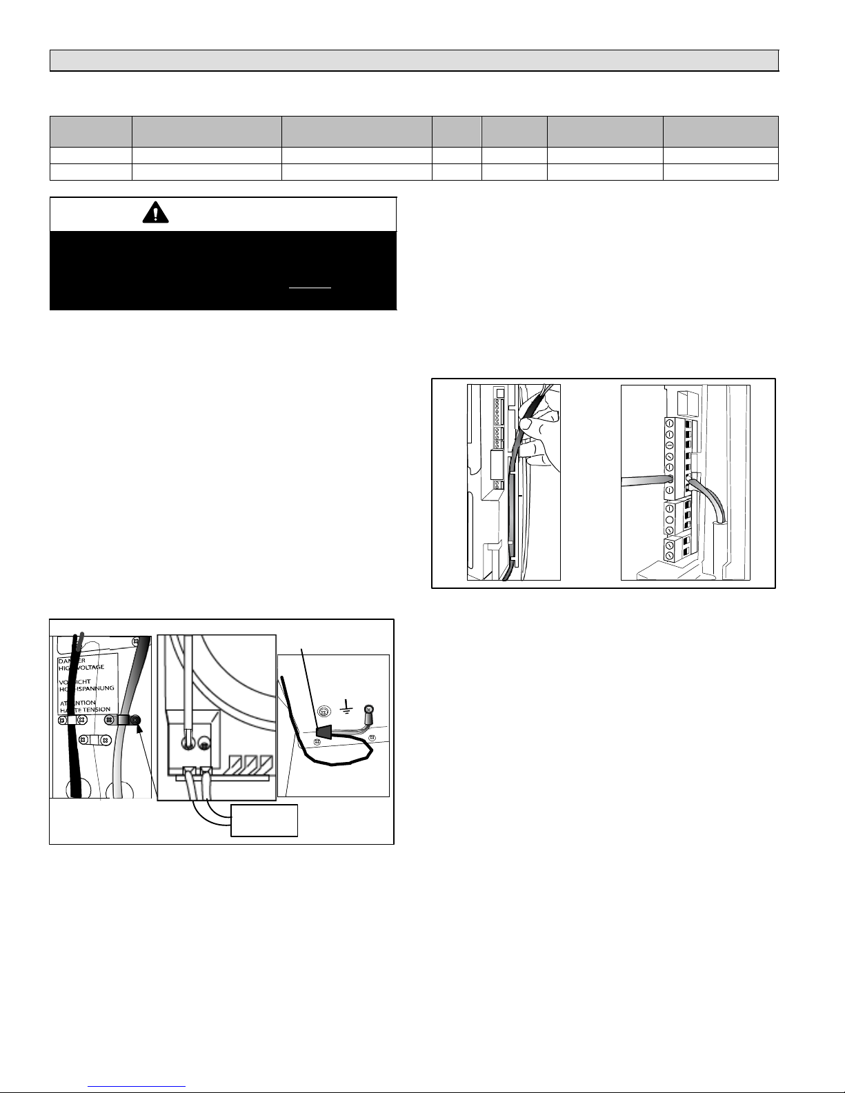
Insert the power and ground connection cables into the
electrical panel compartment using the strain reliefs sup-
plied (see figure 11, A), and connect to the terminals. An
external fused disconnect must be installed.
Check that the power supply voltage to be connected
matches the value indicated on the rating plate inside the
electrical panel.
Connect power wires to the power terminal block located at
the bottom left of the control module, polarity does not mat-
ter (see figure 11, B).
Connect the ground wire to the unit’s chassis ground, lo-
cated just behind the power wiring terminal block (see fig-
ure 11, C).
L1 L2
ABC
SERVICE
DISCONNECT
STRAIN
RELIEF
L1 L2
GND
GND
WIRE NUT
POWER
CONTROL
Figure 11. Power wiring connections
Control wiring
The humidifier is controlled by humidistat and safety
devices such as high−limit humidistat, air proving switch,
and remote on/off.
The humidifier is operated by the closing of a mechanical
humidistat, or by the closing of a normally open dry con-
tact. The most common is a combination of a humidistat
and air proving switch. Diagrams A and B in figure 12 show
the routing to the terminal block.
AB
Figure 12. Routing control wiring to terminal
block
Connect control devices to humidifier using the diagrams
shown in figures 13 through 17. Following each diagram is
an explanation of the sequence of operation associated
with each wiring configuration.
Air Proving Switch and Safety switches
Remove the jumper between terminals AB−AB and con-
nect air proving switch. DO NOT apply any voltage to AB−
AB.
Thread the control wiring through the bottom of the unit,
and the strain relief (see figure 12) and then up the side of
the control module to the top right wiring terminal blocks.
Connect the control wiring to the control wiring terminal
blocks found at the top right side of the control module.

Page 11 HCSTEAM−16/−35 SERIES
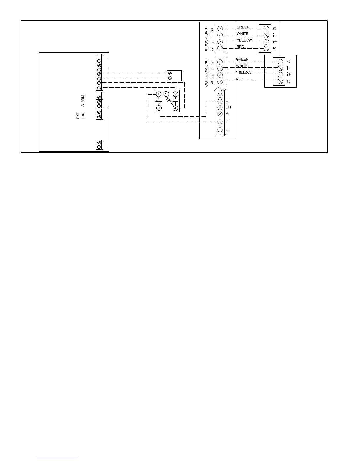
Conventional 24 VAC
Humidistat (Cat no.
X9553 or equivalent)
NO
C
NC
C
NO
Alarm
terminals
(if used)
Outdoor AC Unit
Note 1. Blower interlock is required.
Note 2. 48G96 relay field supplied.
Note 3. Remove factory jumper between AB−AB
48G96 SPDT Interlock Relay
C
NO
Thermostat
Required Air Proving
Switch (provided)
GND
24VAC
N2
GND
N1
AB
AB
GND
IN
Typical Air Handler /
Furnace Control
(AHC or IFC)
(not
used)
(not
used)
Humidifier
low voltage
wiring panel
Figure 13. Humidifier with conventional 24V humidistat and interlocked with HVAC blower
SWhen the humidity in the space falls below the conventional humidistat’s RH set point, the circuit closes from "GND" to "IN"
on the humidifier controller and in turn, closes the EXT FAN contacts ("NO" to "C") in the humidifier controller.
STerminal R on the furnace or air handler feeds 24V to the EXT FAN contacts (now closed) and to the blower interlock relay
coil. The interlock relay normally−open contacts close to energize G" on the furnace or air handler and start the indoor blower
(if not already running by a heating demand). The interlock relay also isolates G" from the thermostat to prevent a back feed
that would start the outdoor unit.
SWhen the indoor blower achieves sufficient speed, the air proving switch contacts close completing the circuit from "AB" to
"AB" on the humidifier controller. Steam production will now start and continue until the humidistat demand is satisfied.
SWhen the humidistat has reached its RH set point, its contacts open stopping steam production. The humidifier controller EXT
FAN contacts open, de−energizing the blower interlock coil and stopping the indoor blower (if not running due to a heating
demand or thermostat blower demand). When the indoor blower stops, the air proving switch contacts will open.
SLP98 Furnace /
CBX40 Air Handler
C
NO
Note 1. Do not connect H" on CS7000 to H" on furnace
or air handler control board.
Note 2. Set up humidifier per CS7000 thermostat installa-
tion instructions.
Note 3. 48G96 relay field supplied.
Note 4. Remove factory jumper between AB−AB.
Outdoor AC Unit
ComfortSense®7000
Thermostat
48G96 Relay
Alarm
terminals
(if used)
(not
used)
(not
used)
(not
used)
Required Air Proving
Switch (provided)
NO
C
NC
C
NO
GND
24VAC
N2
GND
N1
AB
AB
GND
IN
Humidifier
low voltage
wiring panel
Figure 14.Humidifier with ComfortSense®7000 thermostat used as humidistat and interlocked with
HVAC blower
SHumidification is controlled by the humidity sensor in the thermostat. When the humidity in the space falls below the thermo-
stat’s humidity RH set point, 24 volts goes on the thermostat’s "H" terminal to energize the humidifier isolation relay coil which
closes the open set of contacts in the relay, and completes the circuit between "GND" and "IN" on the humidifier controller.
SThe thermostat will also send power to the "G" terminal on the air handler or furnace control to start the indoor blower.
SWhen the indoor blower achieves sufficient speed, the air proving switch contacts close completing the circuit from "AB" to
"AB" on the humidifier controller. Steam production will now start and continue until the humidity demand is satisfied.
SWhen the RH set point is reached, the thermostat removes 24 volts from H" which opens the isolation relay circuit and, in
turn, opens the circuit between "GND" and "IN" on the humidifier controller, stopping steam production. The G" signal will
also be removed to turn off the blower (if not running due to a heating demand or thermostat blower demand). When the indoor
blower stops, the air proving switch contacts will open.
Page 12
506746−01 05/12
SLP98 / icomfort enabled
CBX40UHV / CBX32MV ONLY
icomforttenabled
outdoor unit
icomfort
Touch®
thermostat
Note 1. Humidification must be added in icomfort Touch®
thermostat during commissioning. Refer to icomfort
Touch®Installer Guide for details.
Note 2. 48G96 relay field supplied.
Note 3. Remove factory jumper between AB−AB.
C
NO
48G96
Relay
Alarm
terminals
(if used)
(not
used)
(not
used)
(not
used)
Required Air Proving
Switch (provided)
NO
C
NC
C
NO
GND
24VAC
N2
GND
N1
AB
AB
GND
IN
Humidifier
low voltage
wiring panel
Figure 15. Humidifier with icomfort Touch®thermostat used as humidistat with an icomfortten-
abled SLP98 gas furnace or icomforttenabled CBX40UHV or CBX32MV air handler
SHumidification is controlled by the humidity sensor in the thermostat. When the humidity in the space falls below the thermo-
stat’s humidity RH set point, a demand message for humidification is sent to the HVAC unit control board.
SThe demand message starts the indoor blower and sends a 24 volt signal from the H" terminal on the furnace control to the
humidifier isolation relay coil. The isolation relay contacts close to complete the circuit from GND" and IN" terminals on the
humidifier controller.
SWhen the indoor blower achieves sufficient speed, the air proving switch contacts close completing the circuit from "AB" to
"AB" on the humidifier controller. Steam production will now start and continue until the humidity demand is satisfied.
SWhen the RH set point is reached, the thermostat removes the demand to the furnace board which removes the 24 volt output
from the H" terminal and opens the isolation relay circuit and, in turn, opens the circuit between GND" and IN" on the humidi-
fier controller, stopping steam production. The indoor blower will be turned off (if not running due to a heating demand or ther-
mostat blower demand).
Page 13 HCSTEAM−16/−35 SERIES
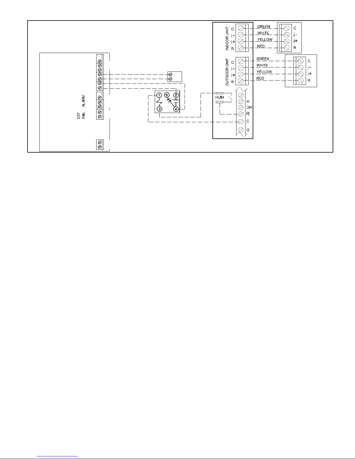
SL280 ONLY
Note 1. Humidification must be added in icomfort Touch®
thermostat during commissioning. Refer to icomfort
Touch®Installer Guide for details.
Note 2. 48G96 relay field supplied.
Note 3. Remove factory jumper between AB−AB.
C
NO
48G96
Relay
Alarm
terminals
(if used)
(not
used)
(not
used)
(not
used)
Required Air Proving
Switch (provided)
NO
C
NC
C
NO
GND
24VAC
N2
GND
N1
AB
AB
GND
IN
Humidifier
low voltage
wiring panel
icomforttenabled
outdoor unit
icomfort
Touch®
thermostat
Figure 16. Humidifier with icomfort Touch®thermostat used as humidistat with an icomfortten-
abled SL280 gas furnace
SHumidification is controlled by the humidity sensor in the thermostat. When the humidity in the space falls below the thermo-
stat’s humidity RH set point, a demand message for humidification is sent to the furnace control board.
SThe demand message starts the indoor blower and closes the "HUM" contacts on the furnace control. 24 VAC passes through
a field−installed jumper from the "R" terminal on the control board, through the closed "HUM" terminals, and to the humidifier
isolation relay coil. The isolation relay contacts close to complete the circuit from "GND" and "IN" terminals on the humidifier
controller.
SWhen the indoor blower achieves sufficient speed, the air proving switch contacts close completing the circuit from "AB" to
"AB" on the humidifier controller. Steam production will now start and continue until the humidity demand is satisfied.
SWhen the RH set point is reached, the thermostat removes the demand to the furnace board which opens the HUM contacts,
opens the isolation relay circuit and, in turn, opens the circuit between "GND" and "IN" on the humidifier controller, stopping
steam production. The indoor blower will be turned off (if not running due to a heating demand or thermostat blower demand).

Page 14
506746−01 05/12
C
NO
ON DIP
1 2 3 4
ON
OFF
OFF
ON
HC DIGITAL AUTOMATIC HUMIDISTAT
DIP SWITCH SETTINGS FOR HUMIDISTAT−
ONLY OPERATION
1
2
5G0
6G
7AOUT
8G0
9NTCE
10DIN Outdoor
Sensor
Outdoor AC Unit
48G96 SPDT Interlock Relay
Thermostat
Typical Air Handler / Fur-
nace Control (AHC or IFC)
Alarm
terminals
(if used)
(not
used)
Required Air Proving
Switch (provided)
HC Digital
Automatic
Humidistat
(Cat.. no.
Y3760)
NO
C
NC
C
NO
GND
24VAC
N2
GND
N1
AB
AB
GND
IN
Humidifier
low voltage
wiring panel
Note 1. Blower interlock is required.
Note 2. 48G96 relay field supplied.
Note 3. Set signal type to 1" for modulating (Step 5, Figure
22 [Page 17]).
Note 4. Remove factory jumper between AB−AB.
Note 5. Connected for Modulating Operation.
Figure 17. Humidifier with HC Digital Automatic Humidistat connected for modulating operation
SSteam production is modulated between 20% and 100% of the maximum production proportionally to the signal provided by
the humidistat.When the humidity in the space falls below the humidistat’s RH set point, the humidistat sends a 0 to 10Vdc
from 7AOUT" terminal to the "IN" terminal on the humidifier controller and in turn, closes the EXT FAN contacts (NO" to C")
in the humidifier controller.
STerminal R on the furnace or air handler feeds 24V to the EXT FAN contacts (now closed) and to the blower interlock relay
coil. The interlock relay normally−open contacts close to energize G" on the furnace or air handler and start the indoor blower
(if not already running by a heating demand). The interlock relay also isolates G" from the thermostat to prevent a back feed
that would start the outdoor unit.
SWhen the indoor blower achieves sufficient speed, the air proving switch contacts close completing the circuit from "AB" to
"AB" on the humidifier controller. Steam production will now start and continue until the humidity demand is satisfied.
SWhen the humidistat has reached its RH set point, its contacts open stopping steam production. The humidifier controller EXT
FAN contacts open, de−energizing the blower interlock coil and stopping the indoor blower (if not running due to a heating
demand or thermostat blower demand). When the indoor blower stops, the air proving switch contacts will open.
C
NO
ON DIP
1 2 3 4
ON
OFF
OFF
ON
HC DIGITAL AUTOMATIC HUMIDISTAT
DIP SWITCH SETTINGS FOR HUMIDISTAT−
ONLY OPERATION
1
2
5G0
6G
7AOUT
8G0
9NTCE
10DIN
Outdoor
Sensor
Outdoor AC Unit
48G96 SPDT Interlock Relay
Thermostat
Typical Air Handler /
Furnace Control
(AHC or IFC)
Alarm
terminals
(if used)
(not
used)
Required Air Proving
Switch (provided)
HC Digital
Automatic
Humidistat
(Cat.. no.
Y3760)
NO
C
NC
C
NO
GND
24VAC
N2
GND
N1
AB
AB
GND
IN
Humidifier
low voltage
wiring panel Note 1. Blower interlock is required.
Note 2. 48G96 relay field supplied.
Note 3. Remove factory jumper between AB−AB.
Note 4. Connected for ON/OFF configuration.
Figure 18. Humidifier with HC Digital Automatic Humidistat connected for ON/OFF operation
SWhen the humidity in the space falls below the humidistat’s RH set point, the circuit closes humidistat terminals 1" and 2"
to complete humidifier controller circuit to IN" and GND" and then closes the humidifier controller EXT FAN contacts ("NO"
to C").
STerminal R on the furnace or air handler feeds 24V to the EXT FAN contacts (now closed) and to the blower interlock relay
coil. The interlock relay normally−open contacts close to energize G" on the furnace or air handler and start the indoor blower
(if not already running by a heating demand). The interlock relay also isolates G" from the thermostat to prevent a back feed
that would start the outdoor unit.
SWhen the indoor blower achieves sufficient speed, the air proving switch contacts close completing the circuit from "AB" to
"AB" on the humidifier controller. Steam production will now start and continue until the humidity demand is satisfied.
SWhen the humidistat has reached its RH set point, output to the humidifier controller "IN" and GND" terminals falls to 0 Vdc,
stopping steam production, then opens the EXT FAN contacts which will stop the indoor blower (if not running due to a heating
demand). When the indoor blower stops, the air proving switch contacts will open.
Page 15 HCSTEAM−16/−35 SERIES
Interlock between HCSteam−16/−35 humidifier and furnace or air handler fan
The following sequence of events must occur for
HCSteam−16/−35 to produce steam:
SExternal humidistat contacts must close between ter-
minals IN and GND providing a steam humidification
demand.
SThe air proving switch NO contacts wired between hu-
midifier terminals AB and AB must close when signifi-
cant air volume is provided to allow the humidifier to
operate.
The HCSteam−16/−35 humidifier must be connected to an
air proving switch (that is, a device that senses the flow of
air in the duct provided by the furnace or air handler). This
air proving switch should be connected to the remote en-
abling input (terminals AB−AB). In some applications a
field−provided limit humidistat (normally closed) may be
installed in series with the air proving switch connected to
terminals AB−AB).
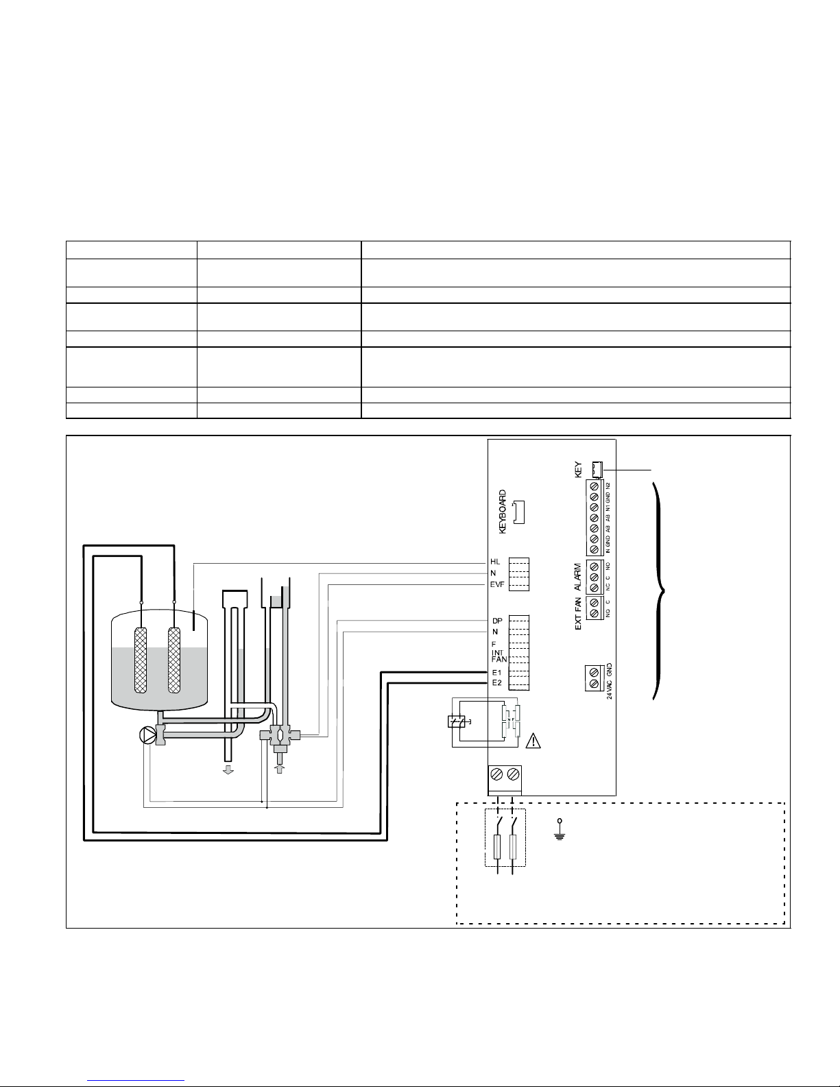
Table 2. Wiring Connections
Terminals Functions Electrical specifications
L1−L2 −GROUND Power supply and Ground
connections
Power supply 110−120 VAC 1−phase 50−60Hz 1.86kW or 220−240 VAC 1−phase 50−60Hz
4.05kW
KEY Programming port Connecting to Programming port or supervisor (factory use only)
AB−AB Remote enabling input Imposes an external NO contact ; Rmax=300 Ohm; Vmax=33 Vdc; Imax=6mAdc;
humidifier enabled = contact closed
IN−GND Control signal input Humidistat connection
NC−C−NO NC alarm contact
Common alarm contact
NO alarm contact
250V; 8Amp max with resistive load; 4 Amp max with inductive load.
In the event of an active alarm, the alarm LED will come on and the relay is energized.
NO−C External fan relay 250V; 8Amp max with resistive load; 4 Amp max with inductive load
24−GND Power for external humidistat Power supply for external humidistat 24 VAC; 2 Watt
Programming port
for factory use
(see low voltage
control diagrams
figures 13
through 17 for
control wiring
options)
Connected to
ground
ON/
OFF
Button
EVF Fill valve
DP Drain pump
DT Drain tempering valve
HL High−level sensor
Power supply
110−120 VAC 1−phase 50−60 Hz
or
220−240 VAC 1−phase 50−60 Hz
External disconnect to
be installed (not sup-
plied); respect local
codes.
For 110−120 VAC, only
switch the hot wire (not
neutral); for 220−240
VAC, switch both hot &
neutral.
2
4
6
8
L1 L2
DP
DT
EVF
HL
Water outlet Water inlet
Steam cylinder unit
NOT
USED
N2
GND
N1
AB
AB
GND
IN
NO
C
NC
C
NO
GND
24VAC
Figure 19. Humidifier internal controller wiring diagram

Page 16
506746−01 05/12
Start−Up
HCSteam−16/−35 humidifier controller
The HCSteam−16/−35 humidifier controller features a com-
prehensive information display that shows the operation of
the system at a glance:
1
2
4
5
6
9
1012
13
14
11
3
7
8
1. Display is % of nominal
capacity
2. Maintenance or adjust-
ment
3. Display is amperage
(default)
4. Steam is being pro-
duced
5. Cylinder filling
6. Foaming
7. Water presence inside
the cylinder
8. Cylinder draining
9. LED icons indicate: left:
operation (green);
middle: power (yellow);
right: alarms (red)
10. Drain button for manual
draining of cylinder and
confirming parameter
values
11. ON/OFF button ("I" de-
pressed is the ON posi-
tion; O" depressed is
OFF)
12. Reset button to reset
alarms and access pa-
rameters
13. Level of output: 33%,
66%, 100%
14. Fan relay is activated.
operation power alarm
Figure 20. Humidifier Controller
WARNING
Before starting, check that the humidifier is in per-
fect condition, that there are no water leaks and that
the electrical parts are dry.
Do not connect power if the humidifier is damaged
or even partially wet!
When installation is complete, flush the supply pipe for 10
minutes by piping water directly into the drain, without
sending it into the humidifier; this will eliminate any scale or
residues that may cause foam when boiling.
Pre start−up checklist
Before starting the humidifier, the following should be
checked:
SWater is connected, the line has been flushed, and ex-
ternal valves are open.
SDrain is connected, run to an open drain, and has a
trap under the unit.
SElectricity is connected in accordance with instruc-
tions, local codes and data labels in the unit.
SMake sure all electrical connections to the cylinder are
tight.
SThe power fuses are installed and intact.
SAll control wiring is complete and tested.
SAir proving switch is wired to close when air flow is
proved.
SHi−limit humidistat (if used) is wired to open on humid-
ity rise above setpoint.
SUnit wires have been checked to make sure they and
all connectors are tight from shipping.
SThe steam hose(s) are run correctly with no sags or
kinks and sloped properly according to the manual.
SCondensate hoses are run correctly with no sags or
kinks and sloped properly according to the manual.
SAn auxiliary drain pain is installed under humidifier if
humidifier is installed in area where a water leak could
cause damage.
Humidifier start up checklist
SInsure that the external power to the humidifier is on.
SPress the I" part of the On/Off button IN. The yellow
Power LED (middle) will light. The HCSteam−16/−35
humidifier is now ready to operate.
SWith a call for humidity, the humidifier will close its
power relays and send power to the electrodes in the
plastic steam generator. The green Operation LED will
light, indicating that operation has begun.
Operation checkout
Check that the air proving switch closes on the lowest
blower speed:
SAfter 10 minutes of operation, check duct for signs of
excessive condensation or wetness by inspecting in-
side of duct (using an access door or by removing the
nozzle).
SIf wetness exists, increase blower cfm or reduce hu-
midifier output capacity.
Initial Start−up with new cylinder
When starting with a new cylinder, you should activate the
cylinder cleaning function as follows:
1. Make sure the humidifier
switch is off (press "O" part
of switch).
2. While pressing and HOLD-
ING both reset/sel" and
drain" buttons, switch the
humidifier back on. DO NOT
release reset/sel" and
drain" buttons until the
wrench icon blinks; then re-
lease both buttons.
3. Press and hold reset/sel" until the display
shows 04. WARNING: DO NOT confirm
any value higher than 04. If 05 or higher is
displayed, press reset/sel" until the dis-
play goes back to the normal operating
mode and restart from step 1.
4. Press and hold drain" (minimum 1
second); the cleaning starts.

Page 17 HCSTEAM−16/−35 SERIES
During cleaning, the electrodes are powered and water fills
until it touches the high−level sensor or the phase current
equals 20A, whichever occurs first. After either of the
events is detected, the steam cylinder is fully discharged
with the electrodes un−powered (the drain pump and the
drain tempering valve are activated for 3 minutes). Lennox
recommends to perform two cleanings when starting a
new humidifier. After the cleaning ends, the humidifier
starts regular operation. The HCSteam−16/−35 humidifier
is now ready for operation.
Operation
Amperage: the amount of current
flowing through the water causing
the water to heat, boil, and pro-
duce steam (default display).
Production %: the amount of
steam being produced (ex-
pressed as a percentage of the
humidifier’s capacity).
Hour counter, expressed in tens;
for instance, when the display
shows 13 the real hour value will
be between 130 and 139 hours.
(Amperage is repeated)
Figure 21. Displaying Information
Displaying information
By pressing the reset/sel" button for 2 seconds, the dis-
play will loop from amperage to production in % of the max-
imum production to the hour counter and back to amper-
age (see figure 21).
Selecting the signal type
NOTE − The HCSteam−16/−35 humidifier is preset for a
manual humidistat with only an ON/OFF feature and nor-
mally does not require any change. Should the need ever
arise to reset it, proceed as follows:
1. Switch the humidifier off.
2. While pressing and HOLD-
ING both reset/sel" and
drain" buttons, switch the
humidifier back on. DO NOT
release reset/sel" and
drain" buttons until the
wrench icon blinks; then re-
lease both buttons.
3. Press reset/sel" until the display shows
02. DO NOT confirm any value higher than
02. Values of 03 or higher not applicable for
these models. If value is higher than 02,
press reset/sel" until the display goes
back to the normal operating mode and re-
start from step 1.
4. Press and hold drain" (mini-
mum 1 second); the display
shows P1" then the present
signal type and then set".
5. Press reset/sel" for signal type of 0 or 1:
0 = On−Off humidistat
1 = external 0...10 Vdc modulating signal
humidistat.
6. Press and hold drain" (minimum 1
second) when done to confirm the new
value of P1 and exit to the normal op-
erating mode.
7. Switch the humidifier off.
Figure 22. Selecting Signal Type
Changing the maximum production percentage
The maximum production can be adjusted between 20%
and 100% of the nominal production in steps of 5% in order
to suit either the 110−120 VAC or 220−240 VAC unit. Default
settings are factory set at 100% (110−120 VAC unit) 70%
(220−240 VAC unit). Adjust capacity per humidity calcula-
tion or system application air flow. Table 3 shows the hu-
midification load requirements. This chart will be helpful in
setting the correct production percentage.
1. Switch the humidifier off.
2. While pressing and HOLD-
ING both reset/sel" and
drain" buttons, switch the
humidifier back on. DO NOT
release reset/sel" and
drain" buttons until the
wrench icon blinks; then re-
lease both buttons.
3. Press reset/sel" until the display shows
01. DO NOT confirm any value higher than
01. Values of 02 or higher not applicable for
these models. If value is higher than 01,
press reset/sel" until the display goes
back to the normal operating mode and re-
start from step 1.
4. Press and hold drain" (mini-
mum 1 second); the display
shows P0" then the current
maximum production percent-
age and then set".
5. Press reset/sel" to change the
Maximum Production in steps of
5% between 20% and 100%.
6. Press and hold drain" (minimum 1
second) to confirm the new maximum
production percentage and exit to the
normal operating mode.
Figure 23. Changing Maximum Production Per-
centage

Page 18
506746−01 05/12
Table 3. Humidification Load Required, Gallon/day [Liter/day] (Ref: AHRI−Guideline F−2008)
Type of
Construction
Volume of Building ft3[m3(approximate)]
8000 [227] 10000 [282] 12000 [340] 16000 [453] 20000 [566] 24000 [680] 32000 [906] 40000 [1133]
Tight 4.3 [16] 5.3 [20] 6.4 [24] 8.5 [32] 10.6 [40.2] 12.7 [48.2] 17.0 [64.4] 21.2[80.4]
Average 8.6 [32] 10.6 [40.2] 12.8 [48.4] 17.0 [64.4] 21.3 [80.2] 25.4 [96.5] 34.0 [148] 42.6 [160]
Loose 12.7 [48.3] 15.9 [60.3] 19.1 [72.6] 25.5 [96.6] 31.8 [121] 38.1 [145] 51.0 [193] 63.6 [241]
Legend: HCSteam−16 HCSteam−35 Exceeds capacity of HCSteam units
Resetting the hour counter
The hour counter must be reset every time the cylinder is
changed in order to reset and restart the internal mainte-
nance timer:
1. Switch the humidifier off.
2. While pressing and HOLD-
ING both reset/sel" and
drain" buttons, switch the
humidifier back on. DO NOT
release reset/sel" and
drain" buttons until the
wrench icon blinks; then re-
lease both buttons.
3. Press reset/sel" until the display shows
03. DO NOT confirm any value higher than
03. Values of 04 or higher not applicable for
these models. If value are higher than 03,
press reset/sel" until the display goes
back to the normal operating mode and re-
start from step 1.
4. Press and hold drain" (minimum 1
second) to confirm: the hour counter
will be reset at once and
HCSteam−16/−35 humidifier will go
back to the normal operating mode.
Figure 24. Resetting Hour Counter
Activating the manual drain
Press and hold the drain" button on the front of the unit
until the cylinder is drained.
NOTE − Water will continue to flow from the tempering
valve after the cylinder is empty. Draining should take
around 20 seconds if the cylinder was full.
Sequence of operation
For a complete description of how the humidifier operates
using the various control devices, see the wiring section
(Page 11 through Page 14).

Page 19 HCSTEAM−16/−35 SERIES
Alarms
In the event of an alarm, the red alarm LED ( ) will flash, the alarm relay will energize and the alarm code will flash in the
display. Multiple alarms will flash in sequence, alternating with the main display. Pressing the reset/sel" button for 2 sec-
onds will reset the alarms, although still active alarms will continue to display.
Display Description Action
Red Alarm
Symbol Notes
−− Remote on−off open. Unit disabled. Off
EE Internal memory error. Unit disabled. On
Replace control for EE & E0
E0 Control board configuration not
valid.
Unit disabled. On
E1 High current alarm. Unit disabled. On Turn off, check connections,
check cylinder (no limescale
bridges between electrodes,
no electrodes short−circuited).
Use a ohm−meter to check
whether they are
short−circuited. Look through
the steam outlet to see
whether the electrodes are
loose.
E2 Low production, low supply water
conductivity or excessive
foam/limescale in the cylinder.
Unit disabled.
Press reset/sel" key for 1 seconds to
reset.
On Check supply water
conductivity (too low?),
replace the cylinder.
E3 Cylinder almost exhausted,
already used for 2000 hrs.
Press reset/sel" key for 1 seconds to
reset.
Off Change cylinder (not urgent).
E4 Fill alarm, unable or slow fill
(current does not increase within
timeout).
Press reset/sel" key for 1 seconds to
reset, otherwise the warning will be reset
automatically every 10 minutes until the
supply water is available again.
On Check water supply, water
inlet strainer, and fill valve;
check drain pump for leakage.
E5 Drain alarm, unable to drain
(current does not decrease within
timeout).
Press reset/sel" key for 1 seconds to
reset.
On Check drain pump operation;
check drain connection.
E6 Cylinder exhausted
(critical performance detected).
The warning is automatically reset if
HCSteam−16/−35 can produce the
demand, otherwise turn off and then on.
Off Change cylinder (urgent).
E7 Foam detected. Press reset/sel" key for 1 seconds to
reset.
Off If it continues, perform some
cleaning cycles (read section
Initial Start−up with a new
cylinder, Page 16)".
E8 Cylinder lifetime expired (3000
hours).
Unit disabled.
Reset the hour counter (read section
Resetting the hour counter").
On Change the cylinder.
E9 High controller temperature
(above 176 °F / 80 °C).
The warning is automatically reset if the
temperature decreases below 176 °F / 80
°C.
Off Check the ambient
temperature near the
controller, replace the
controller if the temperature is
OK.

Page 20
506746−01 05/12
Troubleshooting
Problem Causes Solutions
The humidifier does not turn on 1. No electrical power.
2. On/off switch of the humidifier in position O"
(OFF).
3. Control connectors improperly connected.
4. Power source failure; blown fuse; tripped
breaker.
5. Transformer failure.
1. Check the safety devices upstream from the humidifier and
the presence of power.
2. Close the switch on the panel: position I" (ON).
3. Check that connectors are properly inserted in terminal
block.
4. Check the power source; check condition of fuses; check
for tripped breaker.
5. Check for proper voltage across 24VAC and GND on
control. If no voltage present, replace controller.
The humidifier does not start
operation
1. Remote ON/OFF contact open.
2. The humidistat has not been connected
correctly.
3. Humidistat failure.
4. Control signal not compatible with the type set.
5. Value measured by the humidistat sensor(s)
higher than the corresponding RH set point.
6. Low conductivity water.
1. Close ON/OFF contacts.
2. Check the external connection.
3. Replace the humidistat.
4. Confirm for correct signal type for connected humidistat
using Selecting the signal type procedure on Page 17.
5. Using RH meter, confirm accuracy of RH sensor(s).
6. If 220−240 VAC humidifier, consider installing the Low
Conductivity cylinder (Y3484) listed on Page 23.
The humidifier fills with water
without producing steam
1. High steam back pressure.
2. Fill valve strainer clogged.
3. Mineral buildup in the fill cup.
1. Check that the steam hose is not kinked or sagging,
trapping condensate.
2. Clean the fill valve strainer.
3. Clean the fill cup.
The humidifier wets the duct 1. The steam nozzle is not installed correctly (too
near the top of the duct or the condensate return
is blocked).
2. Air flow rate is too low.
3. Humidifier active when the fan in the duct is off.
1. Check that the steam nozzle is installed correctly.
2. Increase air flow in duct or decrease maximum steam
production setting (see Page 17).
3. Check the connection of the device (flow switch or
differential pressure switch) controlling the humidifier to the
ventilation in the duct.
The humidifier wets the floor below 1. The humidifier drain is blocked.
2. The supply water or overflow circuit has leaks.
3. The condensate drain pipe does not bring the
water back to the drain pan.
4. The steam hose is not properly fastened to the
cylinder.
1. Clean the drain assembly and pan.
2. Check the entire water circuit.
3. Check the correct position of the condensate drain hose in
the drain pan.
4. Check the fastening of the hose clamps on the steam
outlet.
Water in the cylinder turns black 1. Minerals in the cylinder have over concentrated
and are deteriorating the electrodes.
1. Check for sags & kinks that could trap condensate in the
steam hoses that could cause a back pressure on the
cylinder.
2. Check the duct static pressure.
3. Check the fill valve and inlet strainer.
4. Check the drain pump operation.
5. Correct installation problems and replace cylinder.
Heavy arcing occurs within hours
of startup
1. The feed water contains large amounts of Iron,
Copper or other conductive contaminants.
1. If you are using a softener, discontinue use.
2. Check the electrodes in the cylinder to be sure they were
not damaged in shipping. Use a ohm−meter to check
whether they are short−circuited. Look through the steam
outlet to see whether the electrodes are loose.
Humidifier continuously fills and
drains without producing steam
1. Mineral has bridged between the electrodes.
2. There is back pressure from the steam hoses or
duct.
3. The flow regulator in the fill valve is broken or
out of place.
4. Water conductivity is very high.
5. Water is foaming excessively.
1. Perform cleaning cycles or replace the cylinder.
2. Check the steam hoses for kinks or gullies that might be
trapping condensate.
3. Replace the fill valve (stuck open).
4. Consider using a mix of demineralized water with raw
water.
5. Check cylinder − replace if exhausted.
This manual suits for next models
2
Table of contents
Other Healthy Climate Humidifier manuals


