Bogen Nyquist NQ-S1810CT-G2 Instruction sheet

Nyquist Gen 2 VoIP Speakers
Configuration Manual
NQ-S1810CT-G2, NQ-S1810WT-G2
2019 Bogen Communications, Inc.
All rights reserved.
740-00121A
190909


i
Contents
Configuring Nyquist Gen2 VoIP Speakers ................................................................. 1
1 Using the Dashboard...............................................................................3
2 Updating Firmware...................................................................................5
3 Setting Network Tab Parameters........................................................6
4 Setting Configuration Tab Parameters .............................................9
5 Accessing Log Files................................................................................ 10
6 Setting DSP Parameters....................................................................... 13

ii

Configuring Nyquist
Gen2 VoIP
1
Configuring Nyquist Gen2
VoIP Speakers
The Nyquist VoIP Ceiling Speaker Gen 2 (NQ-S1810CT-G2) and
Nyquist VoIP Wall Baffle Speaker Gen 2 (NQ-S18110WT-G2) are VoIP
talkback speakers designed to work with the Nyquist Series IP net-
work based intercom and paging solution.
The ceiling talkback speaker assembly consists of an 8" cone speaker
and VoIP module pre-assembled onto a 13" steel ceiling grille
painted with bright white enamel.
The VoIP wall baffle talkback speaker assembly consists of an 8" cone
speaker and VoIP module pre-assembled onto a bright white injec-
tion molded wall baffle speaker enclosure.
Both types of speakers have a Form-C relay for controlling third-party
devices, are 802.3af compliant, and are designed to facilitate rapid
and efficient deployment using existing network Power over Ethernet
(PoE) ports. These VoIP speakers enable the ease of placement wher-
ever needed within a facility.
A short press of the appliance’s Reset button reboots the device. If
you press the Reset button for 10 seconds, the appliance returns to
the factory default configuration settings. Returning to the default
configuration settings does not change the appliance’s firmware.
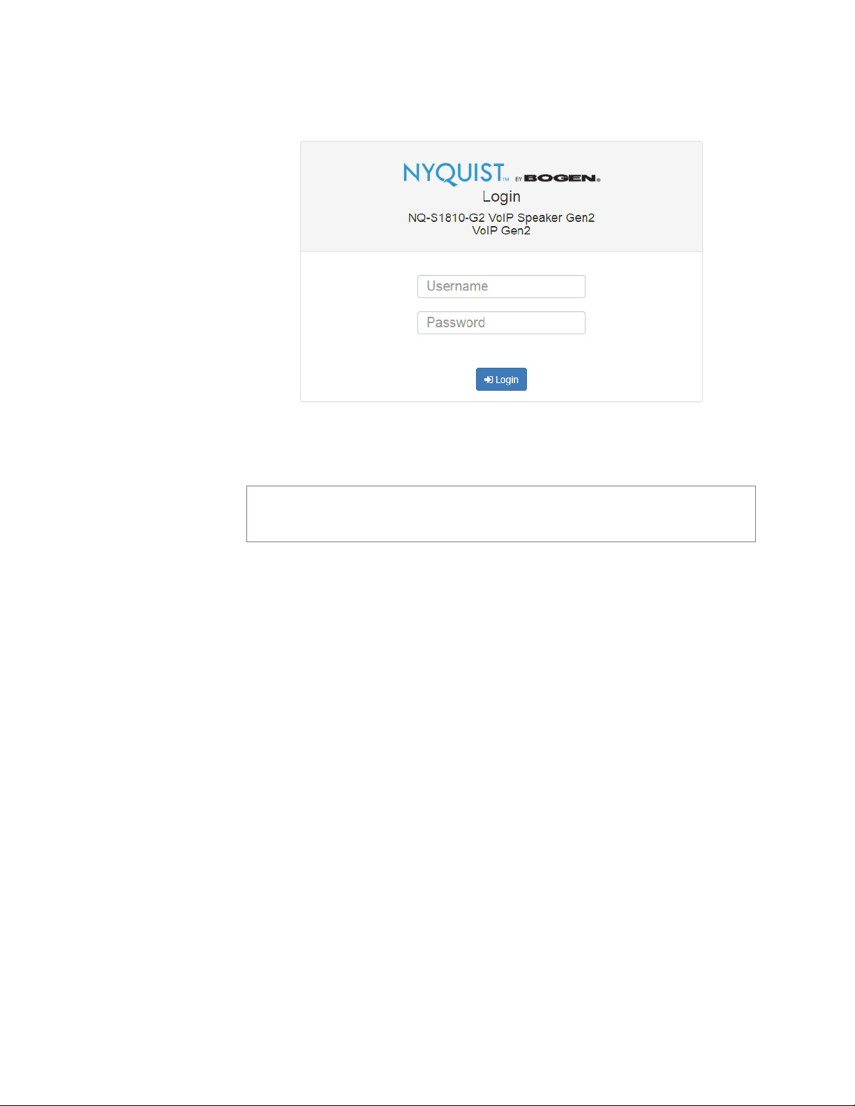
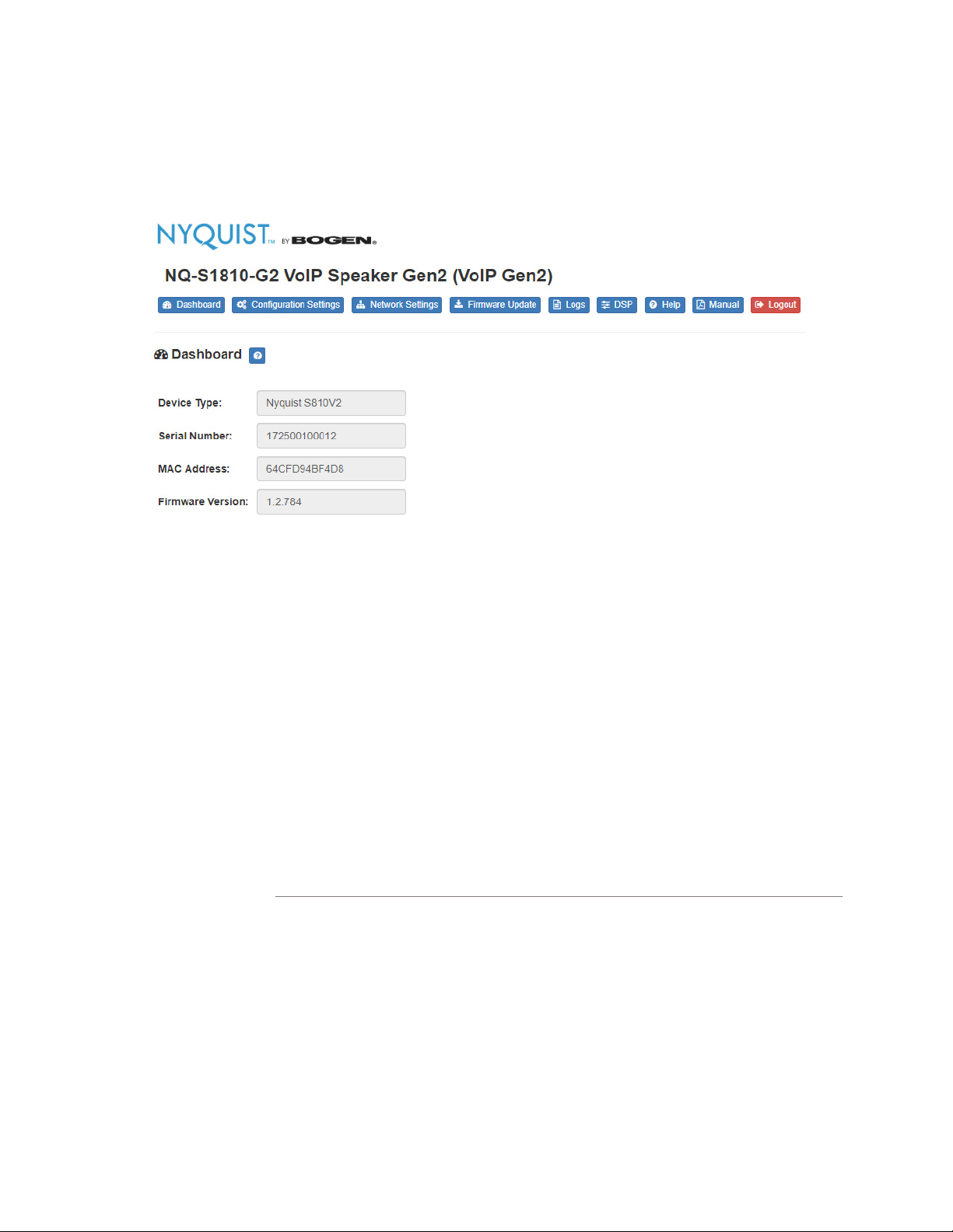
You can let the Nyquist server automatically discover and configure
the Nyquist VoIP speakers, or you can manually configure the speak-
ers through their web-based user interface (web UI). The following
sections describe the process for manual configuration. For informa-
tion about using Nyquist’s automatic configuration process, refer to
the appropriate Nyquist System Administrator Manual.

2
To access the appliance’s UI:
Step 1 Access the appliance’s web UI by doing one of the fol-
lowing:
a On your web browser, enter the IP address for the
appliance as the URL.
b From the Nyquist web UI navigation bar, select Sta-
tions, select Stations Status, navigate to the device
that you want to configure, and then select the Link
icon.
Step 2 At the Nyquist Appliance - Login page, enter username
and password, and then select Login.|
The default username is admin; the default password is
bogen.
The dashboard for the selected appliance appears.
Figure 1, Nyquist Appliance Login
Note: Do not use third-party Chrome browser extensions with the
Nyquist user interface.

3
1 Using the Dashboard
The dashboard displays the following read-only fields:
Figure 2,
Table 1, Appliance Dashboard Read-Only Fields
Device Type Identifies the physical device used by the
station.
Serial Number Identifies the serial number for the device.
MAC Address Specifies the Media Access Control (MAC)
address, which is a unique identifier
assigned to network interfaces for commu-
nications on the physical network segment.
Firmware Version Provides the firmware version installed on
the station.

4
The dashboard also contains the following buttons:
Table 2, Appliance Dashboard Buttons
Dashboard Refreshes the dashboard.
Configuration Set-
tings
Accesses the Configuration Settings page
where you can either manually set various
options, such as the SIP Username, or
select to receive configuration settings
from the server.
Network Settings Accesses the Network Settings page where
you can view and set network settings,
such as the static IP address.
Firmware Update Accesses the Firmware Update page where
you can view the current Nyquist version,
check for updates, restore factory settings,
and reboot the appliance.
Logs Accesses log files, which record either
events or messages that occur when soft-
ware runs and are used when trouble-
shooting the appliance.
DSP Accesses the DSP page where you can view
and set parameters for Digital Signal Pro-
cessing (DSP).
Help Accesses the appliance’s online help.
Manual Displays the Nyquist VoIP Speaker Configu-
ration Manual.
Logout Logs out of the appliance’s dashboard.

5
2Updating Firmware
When you select Firmware Update from the appliance’s web UI, the
Firmware Update page appears. From this page you can determine
which Nyquist version the appliance is using and if an update is
required. You can also use this page to restore factory settings and to
reboot the appliance.
To use the Firmware Update page:
Step 1 On the appliance web UI’s main page, select Firmware
Update to ensure you have the latest firmware version.
Step 2 Select Upload Firmware to upload firmware from the
server to the appliance.
If you select this option, a popup screen appears that
Note: A Nyquist appliance connected to the Nyquist network receives a config-
uration file from the Nyquist server that includes the latest firmware available
from the server. If the firmware is later than the one installed on the appliance, an
automatic firmware update occurs unless the Firmware parameter for the sta-
tion is left blank. Refer to the Nyquist System Administrator Manual for more
information.
Figure 3, Firmware Update Page

6
allows you to select the file that you want to upload.
You can navigate to the file’s location. After you select
the file, select Upload. If Nyquist discovers a new firm-
ware version, the Firmware Update page displays an
Update Firmware button. Select this button if you
want to update the appliance’s firmware to the new
version.
Step 3 If you want to return your appliance to its original state
(undoing firmware updates), select Restore Factory
Settings.
Step 4 Select Reboot Appliance to restart your appliance.
3 Setting Network Tab Parameters
Network settings can be configured dynamically by the Nyquist
server or manually by using the appliance’s web UI.
To manually configure network settings:
Step 1 On the appliance web UI’s main page, select Network
Settings.
Step 2 Select your desired network settings.
Step 3 Select Save.

7
Network settings are described in the following table:
Figure 4, Network Settings
Table 3, Network Settings
Static IP Identifies the fixed IP address assigned
to the appliance by a system administra-
tor.
Netmask Identifies the subnetwork subdivision of
an IP network.
Gateway Identifies the address, or route, for the
default gateway.
VLAN ID Identifies the Virtual Local Area Network
(VLAN) for this appliance. Values range
from 0 to 4094.

8
VLAN Priority Identifies the priority of the network traf-
fic on the VLAN. Priority can range from
0 through 7.
NTP Server Identifies the IP address or the domain
name of the Network Time Protocol
(NTP) Server. This field is read only.
TFTP Server Identifies the IP address of the Trivial File
Transfer Protocol (TFTP) server. TFTP is
used by Nyquist VoIP phone and appli-
ance provisioning. A TFTP server runs on
the Nyquist server on port 69 (the stan-
dard TFTP port #).
Device provisioning files are stored on
the Nyquist server in directory: /srv/
tftp. This is the only directory
exposed by the TFTP server.
DHCP Server Over-
ride
Indicates if you want to override the
TFTP server information provided by the
Dynamic Host Configuration Protocol
(DHCP) via option_66.
DHCP supplies IP addresses to the
Nyquist server and associated devices. It
also supplies the TFTP server IP address
or name via option_66.
DHCP Enabled Indicates if the device is enabled to use
DHCP.
Reboot Appliance Allows you to save the network options
and reboot the appliance.
Table 3, Network Settings (Continued)

9
4 Setting Configuration Tab Parameters
The easiest way to configure Nyquist appliances is to obtain configu-
ration settings from the Nyquist server by selecting Get Configura-
tion From Server. However, you can manually configure an
appliance through the appliance’s Web UI.
To manually configure your Nyquist appliance:
Step 1 On the appliance Web UI’s main page, select Configu-
ration Settings.
Step 2 Select your desired settings.
Step 3 Select Save.
The following table describes the Configuration tab settings:
Note: Manual configuration will be overwritten by the server once the appli-
ance is connected and discovered by the server.
Table 4, Configuration Settings
Web Username Provide a web username for this appli-
ance.
Web Password Provide a web password for logging into
the appliance.
Web Confirm Pass-
word
Re-enter the password used to log into
the appliance.
SIP Username Provide the username used for Session
Initiation Protocol (SIP) device registra-
tion.
SIP Password Provide the password used for SIP device
registration.
SIP Confirm Pass-
word
Re-enter the password used for SIP device
registration.
Server Identifies the IP address of the Nyquist
server.

10
5 Accessing Log Files
A log file records either events or messages that occur when software
runs and is used when troubleshooting the appliance. From the
appliance’s web-based UI, log files can be viewed directly or exported
via download to your PC, Mac, or Android device and then copied to
removable media or attached to an email to technical support.
To view a log file:
Step 1 On the appliance Web UI’s main page, select Logs.
Step 2 From the drop-down menu, select the log that you
want to view.
Multiple versions of the same log and zipped copies of
the log may be available.
Step 3 To export the file, select Export.
A link to a .txt file appears in the screen’s lower left.
Local Port Identifies the local port.
Emergency-All-Call Identifies the IP address, port number, and
volume used for emergency all-calls
pages.
All-Call Identifies the IP address, port number, and
volume used for all-calls pages.
Audio Distribution Identifies the IP address, port number, and
volume used for audio distribution.
Multicast # Identifies the multicast IP address for a
zone that the speaker is included in. If a
speaker is added to multiple zones, the
multicast IP address for each zone
appears.
Table 4, Configuration Settings (Continued)

11
Available logs are described in the following table:
Figure 5, Logs
Table 5, Logs
Log Description
alternatives.log Contains information by the update-alternatives, which
maintain symbolic links determining default com-
mands.
ampws.log Contains information about protection status and logs
protection events with temperature information at the
time of event.
auth.log Contains system authorization information, including
user logins and authentication methods that were
used.
bootstrap.log Contains information actions, errors, and warnings that
occur during booting of the appliance.
btmp Contains information about failed login attempts.

12
daemon.log Contains information logged by the various back-
ground daemons that run on the system.
debug Contains errors and debug information.
dmesg Contains kernel ring buffer information. When the sys-
tem boots up, the screen displays information about
the hardware devices that the kernel detects during the
boot process. These messages are available in the ker-
nel ring buffer, and whenever a new message comes,
the old message gets overwritten.
dpkg.log Contains information that is logged when a package is
installed or removed using dpkg command.
faillog Contains user failed login attempts.
kern.log Contains information logged by the kernel and recent
login information for all users.
lastlog Contains information on the last login of each user.
messages Contains messages generated by Nyquist.
php5-fpm.log Contains errors generated by the PHP script.
syslog Contains list of errors that occur when the server is run-
ning and server start and stop records
user.log Contains information about all user level logs.
wtmp Contains historical record of users logins at which ter-
minals, logouts, system events, and current status of
the system, and system boot time.
wvdialconf.log Contains basic information about the modem port,
speed, init string, and Internet Service Provider (ISP).
Table 5, Logs (Continued)
Log Description

13
6 Setting DSP Parameters
When you select DSP from the appliance’s web UI, the DSP page
appears.
From this page, you can set parameters for DSP, which is a form of
processing that uses bit data to simulate characteristics found in
analog circuits. With DSP, you can alter analog signals, such as audio
or video signals, that have been converted to a digital format.
You can also select Save Settings to Server to back up all configura-
tion settings to the Nyquist server.
Figure 6, DSP Page with Popup Menu

14
The DSP page shows the Level selections for the Output channel.
Selecting the Menu icon above the Output channel displays a menu
that allows you to select DSP parameters. that are described in the
following table:
6.1 Intercom Tuning
Selecting Intercom Tuning from the Menu icon on the DSP page
displays the Intercom Tuning dialog box.
Table 6, DSP Parameters
Intercom Tuning Allows you to set settings used in intercom
calls.
Presets Allows you to use preset DSP settings for the
selected Speaker Type.
Figure 7, Intercom Tuning

15
The Intercom Tuning dialog box has LEDs for input and output sig-
nals and contains two settings.
6.2 Presets
Selecting Presets from the Menu icon on the DSP page displays the
Presets dialog box.
The Presets dialog box allows you to select the Speaker Type.
Options are: NQ-S1810WT or NQ-S1810CT.
Table 7, Intercom Tuning Settings
Switching
Sensitivity
Specifies the input level at which point the
Admin Phone takes over for the speaker. The
range is -90 to -20 dB.
Mute Level Specifies the negative gain applied to the
microphone when in talkback mode. The
range is -90 to -20 dB.
Figure 8, Presets

16
Other manuals for Nyquist NQ-S1810CT-G2
3
This manual suits for next models
3
Table of contents
Other Bogen Speakers manuals

Bogen
Bogen ASWB1 Guide

Bogen
Bogen SMTB User manual

Bogen
Bogen PRO BP12DSP Guide

Bogen
Bogen NEAR A-Series A12 User manual

Bogen
Bogen 14018 User manual

Bogen
Bogen NEAR LB4TM User manual

Bogen
Bogen Bogen NEAR ORBIT OPS1 Guide

Bogen
Bogen NEAR Orbit OCS1 Guide

Bogen
Bogen BDT30A User manual

Bogen
Bogen FG15 User manual