Bogen Nyquist NQ-S1810CT-G2 User manual

VoIP Speaker Configuration Guide
NQ-S1810CT-G2, NQ-S1810WT-G2
© 2021 Bogen Communications LLC
All rights reserved
740-00121B
230421

i
Contents
Configuring the Nyquist VoIP Speakers . . . . . . . . . . . . . . . . . . . . . . . . . . . . . . . . . . . 1
Using the Dashboard . . . . . . . . . . . . . . . . . . . . . . . . . . . . . . . . . . . . . . . . . . . . . . . . . . . . . . . .3
Standalone Operation . . . . . . . . . . . . . . . . . . . . . . . . . . . . . . . . . . . . . . . . . . . . . . . . . . . . . . . .5
Updating Firmware . . . . . . . . . . . . . . . . . . . . . . . . . . . . . . . . . . . . . . . . . . . . . . . . . . . . . . . . . .5
Network Settings Tab Parameters . . . . . . . . . . . . . . . . . . . . . . . . . . . . . . . . . . . . . . . . . . . . .7
Configuration Settings Tab Parameters . . . . . . . . . . . . . . . . . . . . . . . . . . . . . . . . . . . . . . . .10
Standalone Operation Configuration Settings . . . . . . . . . . . . . . . . . . . . . . . . . . . . . . . .13
Setting DSP Parameters . . . . . . . . . . . . . . . . . . . . . . . . . . . . . . . . . . . . . . . . . . . . . . . . . . . . .19
Setting the Channel Level. . . . . . . . . . . . . . . . . . . . . . . . . . . . . . . . . . . . . . . . . . . . . . . . . .20
Adjusting Volume Levels . . . . . . . . . . . . . . . . . . . . . . . . . . . . . . . . . . . . . . . . . . . . . . . . . .20
Knob Adjustments . . . . . . . . . . . . . . . . . . . . . . . . . . . . . . . . . . . . . . . . . . . . . . . . . . . . . . . .20
Intercom Tuning. . . . . . . . . . . . . . . . . . . . . . . . . . . . . . . . . . . . . . . . . . . . . . . . . . . . . . . . . .21
Presets . . . . . . . . . . . . . . . . . . . . . . . . . . . . . . . . . . . . . . . . . . . . . . . . . . . . . . . . . . . . . . . . . .23
Accessing Log Files . . . . . . . . . . . . . . . . . . . . . . . . . . . . . . . . . . . . . . . . . . . . . . . . . . . . . . . . .25
Appendix A: Bogen Digital Certification Authority . . . . . . . . . . . . . . . . . . . . . . . . . 27
Installing the Bogen Digital Certification Authority . . . . . . . . . . . . . . . . . . . . . . . . . . . . . .27
Installing Certification Authority on Windows System . . . . . . . . . . . . . . . . . . . . . . . . .27
Installing Certification Authority on Mac System. . . . . . . . . . . . . . . . . . . . . . . . . . . . . .28
Installing Certification Authority on an Android Device . . . . . . . . . . . . . . . . . . . . . . . .29
Installing Certification Authority on an iOS Device . . . . . . . . . . . . . . . . . . . . . . . . . . . .29
Viewing the Certificate . . . . . . . . . . . . . . . . . . . . . . . . . . . . . . . . . . . . . . . . . . . . . . . . . . . .29

1
Configuring the Nyquist VoIP Speakers
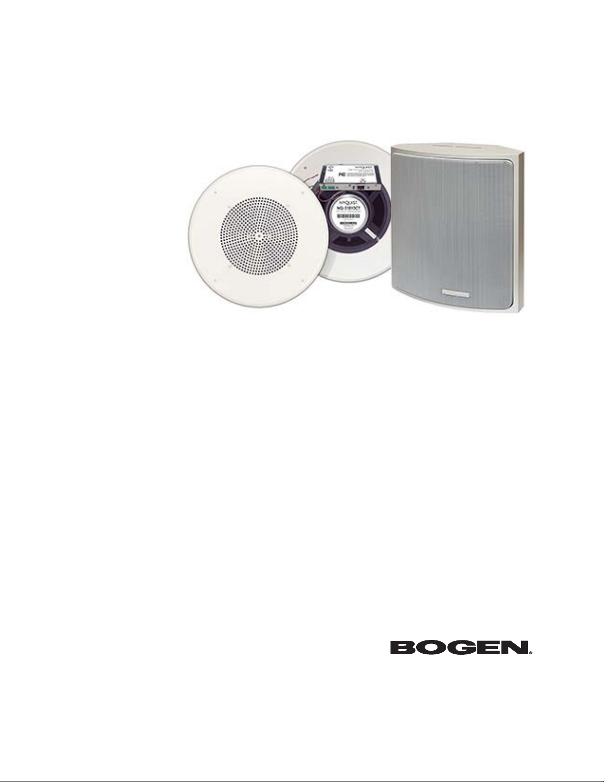
The Nyquist VoIP Ceiling Speaker Gen 2 (NQ-S1810CT-G2) and Nyquist VoIP Wall Baffle
Speaker Gen 2 (NQ-S1811WT-G2) are VoIP talkback speakers designed to work with the
Nyquist Series IP network-based intercom and paging solution.
The ceiling talkback speaker assembly consists of an 8" cone speaker and VoIP module
preassembled onto a 13" steel ceiling grille painted with bright white enamel.
The VoIP wall baffle talkback speaker assembly consists of an 8" cone speaker and VoIP
module preassembled onto a bright white injection-molded wall baffle speaker enclo-
sure.
Both types of speakers are 802.3af-compliant and are designed to facilitate rapid and effi-
cient deployment using existing network Power over Ethernet (PoE) ports. They also have
a Form-C relay for controlling third-party devices. These VoIP speakers enable ease of
placement wherever needed within a facility.
A two-second press of the appliance’s Reset button reboots the device. If you press the
Reset button for 10 seconds, the appliance returns to the factory default configuration
settings. Returning to the default configuration settings does not change the appliance’s
firmware.
The following sections describe the process for manual configuration. For information
about using Nyquist’s automatic configuration process, refer to the appropriate Nyquist
System Administrator Guide.
Note: Do not use third-party Chrome browser extensions with the Nyquist user interface.
To access the appliance’s Web-based user interface (UI):
1Before accessing the web UI for the first time, the Bogen Certification Authority (CA)
digital certificate must be installed on the client. This certificate can be downloaded
from any Nyquist appliance and enables your browser to recognize the Nyquist web
application as a trusted site.
For details on how to download and install the certificate to your client computers,
see "Installing the Bogen Digital Certification Authority” on page 27.
2Access the appliance’s web UI by doing one of the following:
a) On your web browser, enter the IP address for the appliance as the URL.
b) From the Nyquist server’s web UI navigation bar, select Stations, select Stations
Status or Appliance Status, navigate to the device that you want to configure,
and then select the Link icon.

2
3At the Nyquist appliance’s Login page, enter username and password, then press
enter or click on the Login button.
The default username is admin; the default password is bogen.
Note: After a successful login, a warning will be displayed if the default password is still in
use. We strongly encourage changing the default password as soon as possible.
When you have logged in successfully, you will be presented with the dashboard for the
appliance.
Figure 1. Nyquist Appliance Login

3
Using the Dashboard
The dashboard displays the following fields:
Figure 2. Nyquist Speaker Dashboard
Note: On the Dashboard, the Device Type Nyquist S1810V2 refers to the Nyquist S1810-G2.
Table 1. Appliance Dashboard Fields
Device Type Identifies the model of this device.
Serial Number Identifies the serial number for the device.
MAC Address Identifies the Media Access Control (MAC) address,
which is a unique identifier assigned to network inter-
faces for communications on the physical network seg-
ment.
Firmware Version Identifies the firmware version installed on the device.
Relay Trigger Status When enabled in Configuration Settings, this field
indicates the status of the NO/NC output relay, which is
activated whenever an audio signal is being sent to the
VoIP speaker.

4
The following buttons are available at the top of all pages in the application.
Standalone Operation Enables or disables Standalone mode.
Volume Cut Level (dB) Specifies a temporary volume setting for the speaker
during the current intercom call or page.
Note: This is a temporary adjustment that allows the user to experi-
ment with the loudness of the speaker and will be reset to the nor-
mal setting on subsequent calls. To make permanent adjustments,
change the station-specific cut level settings on the Nyquist System
Controller.
The value can be adjusted between −42 and 0 dB.
Table 2. Appliance Dashboard Buttons
Dashboard Displays the dashboard.
Configuration Settings Accesses the Configuration Settings page where you can
view and set various options. If Standalone Operation is
not enabled, you can also receive configuration settings
from a Nyquist server.
Network Settings Accesses the Network Settings page where you can view
and set network settings, such as the static IP address.
Firmware Update Accesses the Firmware Update page where you can view
the current Nyquist version, update firmware to a new
version, restore the configuration to factory defaults,
and reboot the appliance.
Logs Accesses log files, which record either events or mes-
sages that occur when software runs and are used when
troubleshooting the appliance.
DSP Accesses the DSP page where you can view and set
parameters for Digital Signal Processing (DSP).
Help Accesses the appliance’s online help.
Manual Displays this appliance’s configuration guide.
Logout Logs out of the appliance’s web UI.
Table 1. Appliance Dashboard Fields

5
Standalone Operation
This device can also run in Standalone Operation mode, where it will not interact with a
Nyquist server (e.g., E7000 or C4000). This means the device will not:
• Fetch device configuration from Nyquist server
• Register with Nyquist server (via SIP)
• Store backup information to Nyquist server
• Allow access to Nyquist server-based NTP
Standalone Operation allows this device it to be used without a Nyquist server as a
generic SIP endpoint when integrated with a 3rd-party VoIP telephone system or other
SIP server-based solutions, such as a unified communications (UC) platform. In a non-SIP
environment, these devices are capable of receiving audio through one or more priori-
tized multicast channels.
Updating Firmware
When you select Firmware Update from the appliance’s web UI, the Firmware Update
page appears. From this page you can determine which Nyquist firmware version the
appliance is using and if an update is available. You can also load a firmware release,
install the loaded firmware, restore the configuration to factory defaults, and reboot the
appliance.
Note: A Nyquist appliance connected to the Nyquist network receives a configuration file
from the Nyquist server that includes the latest firmware available from the server. If the
firmware is different from the one installed on the appliance, an automatic firmware
update occurs unless the Firmware parameter for the station is left blank. Refer to the
Nyquist System Administrator Guide for more information.

6
To use the Firmware Update page:
1On the appliance web UI’s main page, select Firmware Update to view or update the
firmware version.
• If the device is in Standalone mode, the Check for Updates button will be shown.
Selecting it checks the Bogen website for the latest firmware version available. If a
version newer than the one currently installed is found, it is downloaded to the
appliance and the Update Firmware button will be shown.
• If you already have a firmware file you would like to install to the appliance, select
Upload Firmware to upload the firmware file from your computer to the appli-
ance. A popup screen appears that allows you to select the file that you want to
upload. You can navigate to the file’s location. After you select the file, select
Upload.
The page displays the uploaded firmware version (“New Nyquist Version”) and an
Update Firmware button appears. Select this button if you want to update the
appliance’s firmware to the uploaded version.
• If you want to return your appliance to its original factory configuration, select
Restore Factory Settings.
• Select Reboot Appliance to restart your appliance.
Note: Some buttons only appear on this page when applicable.
Figure 3. Firmware Update Page

7
Network Settings Tab Parameters
Network settings can be configured dynamically by the Nyquist server or manually by
using the appliance’s web UI.
To manually configure network settings:
Table 3. Firmware Update settings
Current Nyquist Version Shows the version of the appliance’s currently
installed firmware.
New Nyquist Version Shows the version of the firmware that has been
loaded, though not installed, onto the appliance.
Update Firmware Available only when a new firmware version has
been loaded onto the appliance (as specified in
New Nyquist Version).
Installs the loaded firmware. A reboot may be
required after installation.
Upload Firmware Prompts the user to specify a firmware file, which
will then be loaded (though not installed) onto the
appliance.
Note: To obtain the firmware file for a specific version, please
contact Bogen Technical Support.
Check for Updates Available only when the appliance is configured
for Standalone mode.
Checks the Bogen website for the latest firmware
version available and, if it finds a version newer
than what is currently installed, downloads it to
the appliance.
Note: Ensure your Nyquist appliance has network access to
bogen-ssu.bogen.com, port 22.
Restore Factory Settings Returns the appliance to its original factory con-
figuration.
Note: This does not install the original appliance firmware.
The firmware will not be changed.
Reboot Appliance Restarts the appliance.

8
1On the appliance web UI’s main page, select Network Settings.
2Select your desired network settings.
3Select Save.
Network settings are described in the following table:
Figure 4. Network Settings
Table 4. Network Settings
IP Address Identifies the IP address assigned to the appliance.
Netmask Identifies the subnetwork subdivision of an IP net-
work.
Gateway Identifies the address, or route, for the default gate-
way.
VLAN ID Identifies the Virtual Local Area Network (VLAN) for
this appliance. Values range from 0 to 4094.

9
VLAN Priority Identifies the priority of the network traffic on the
VLAN. Priority can range from 0 through 7.
NTP Server Identifies the IP address or the domain name of the
Network Time Protocol (NTP) Server.
Note: This field is only editable when Standalone Operation is
enabled.
TFTP Server Identifies the host name or IP address of the Trivial
File Transfer Protocol (TFTP) server.
The specified TFTP server can be used to automati-
cally set this device’s Configuration settings via the
Get Configuration from Server button.
If TFTP Server from DHCP (see below) is set to “Yes”,
this value will be auto-configured via DHCP option
66, assuming the DHCP server has been configured
to provide option 66. For details, see the documenta-
tion for your DHCP server.
Note: A TFTP server runs on the Nyquist server on port 69 (the
standard TFTP port) and the optional Nyquist DHCP service
automatically provides this TFTP address via option 66.
Note: If this value is unspecified, the TFTP Server from DHCP
will automatically be set to “Yes”, this field will become read-
only, and DHCP will be used to configure this setting. To change
this value, the TFTP Server from DHCP setting must be set to
No, which makes the field editable.
Note: This setting is not available when Standalone Operation is
enabled.
TFTP Server from DHCP “Yes” means the device will use the DHCP option 66
value to retrieve an address for the TFTP Server from
DHCP.
“No” means the device will ignore the DHCP
option 66 value and use the manually configured
value of the TFTP Server (see above).
Note: This setting is not available when Standalone Operation is
enabled.
DHCP Enabled Indicates if the device is enabled to use DHCP to
retrieve its IP configuration.
Reboot Appliance Indicates that this appliance should reboot when the
Save button is clicked.
Table 4. Network Settings (Continued)

10
Configuration Settings Tab Parameters
The easiest way to configure Nyquist appliances is to obtain configuration settings from
the Nyquist server by selecting Get Configuration From Server. However, you can man-
ually configure an appliance through the appliance’s Web UI when Standalone Operation
is enabled (see "Configuration Settings (Standalone disabled)” on page 11).
To view the Nyquist appliance configuration:
1On the appliance Web UI’s main page, select Configuration Settings.
2View the settings as described in Table 5 on page 11 for normal configuration, or
modify the settings as described in "Configuration Settings (Standalone disabled)” on
page 11 for Standalone Operation configuration.
3If changes were made (Standalone Operation only), click the Save Configuration
Settings and/or Save Multicast Addresses buttons to save your changes.
Figure 5. Appliance Configuration Settings (Standalone disabled)

11
The following table describes the Configuration Settings tab settings:
The Configuration Settings tab also displays the following information for each Device
Station attached to the amplifier:
Table 5. Configuration Settings (Standalone disabled)
Get Configuration from
Server
Retrieves configuration settings (i.e., web username,
server, and local port) from the TFTP server specified in
the Network Settings (see "Network Settings Tab
Parameters” on page 7).
Web Username Displays the username of the current user.
Emergency-All-Call Identifies the IP address, port number, cut level (vol-
ume), and station list used for emergency all-call
pages.
All-Call Identifies the IP address, port number, cut level (vol-
ume), and station list used for all-call pages.
Audio Distribution Identifies the IP address, port number, cut level (vol-
ume), and station list used for audio distribution.
Multicast # Identifies the IP address, port number, cut level (vol-
ume), and station list used for the multicast audio
stream of a specific zone. If this device belongs to
more than one zone, then multiple Multicast # entries
will be displayed.
Nyquist Control Password Specifies a password used to secure Nyquist control
messages between this device and the Nyquist server.
This value must match the password specified on the
Nyquist server to support certain Nyquist features,
such as sound masking, amp protection mode, and sta-
tion check-in.
The specified password must be exactly 20 characters
long and include uppercase, lowercase, and numeric
characters.
Note: This password cannot be set unless the Web Password has
been changed from the default value.
Port Number Identifies the port number of the appliance.
Port Type Identifies the station type to which the port connects.

12
Account ID Identifies the SIP account (IP address) associated with
the device preceded by the extension of the device
associated with this port.
Local Port Identifies the port used for SIP.
Username Identifies the username or extension for the station
associated with the port.

13
Standalone Operation Configuration Settings
Configuring this device consists of specifying one or more of the following:
• The SIP server addresses, ports, and SIP extensions at which to register for incoming
SIP calls.
• The input multicast (Receive) addresses (and ports) from which the device will receive
encoded signals, which will then be converted to analog and played to the speaker.
To receive networked audio, configure one or more Multicast Addresses (Receive)
entries with the multicast addresses, ports, and codecs from which to receive the encoded
streams. Specify the cut level for the speaker output channel.

14
The following table describes the Configuration Settings tab settings when Standalone
Operation is enabled for this device:
Figure 6. Appliance Configuration Settings (Standalone enabled)

15
Table 6. Configuration Settings (Standalone enabled)
Device Type Displays the type of this device.
Device Name Provides a name for this device.
Web Username Specifies a web username for this appliance.
Web Password Specifies a web password for logging into the appliance.
Web Confirm Password Re-enter the password used to log into the appliance.
Time Zone Specifies the time zone in which the device resides.
Output Power (Watts) Specifies the output power for the amplifier in Watts.
Valid values are: 1/8, 1/4, 1/2, 1, 2, 4, and 8.
Enable SIP Calls Enables this device to receive one-way SIP calls, wherein
only the caller can be heard (such as announcements). If
enabled, a number of SIP-related configuration settings
are displayed.
External Relay Trigger Enables/disables the activation of the NO/NC output relay
to notify an external device that an audio signal is being
sent to the VoIP speaker.
SIP Server AddressaSpecifies the IP address of the SIP Registration Server with
which the device will register.
SIP CodecsaDisplays a read-only list of codecs allowed on SIP sessions.
SIP ExtensionaSpecifies the SIP extension for this device.
The extension, along with the IP address, is used to specify
the URI used to place a SIP call to this extension:
sip:<extension>@<local_ip_address>
SIP Network PortaSpecifies the IP port on which to communicate with the
SIP Registration Server (typically 5060).
SIP User NameaSpecifies the SIP user name used to register with the SIP
server.
SIP PasswordaSpecifies the SIP registration password used to register
with the SIP server.
TypeaSpecifies how the device will be used. Options are:
• VoIP Speaker Only
• Digital Call Switch & Speaker

16
The following parameters appear for each Multicast Address configured for this device.
Dial ExtensionaOnly available when Type is set to Digital Call Switch &
Speaker, this indicates which extension will be called when
the call button is activated.
Intercom Cut LevelaSpecifies the output level of the speaker.
This can be a value from −42 and 0 dB.
The default value is −6 dB.
Note: To modify, click on the value, adjust the slider on the popup
using the cursor keys or mouse, and click the check box button.
a. Available only when Enable SIP Calls has a value of Yes.
Multicast IP Address Specifies the multicast IP address on which to receive
audio streams.
Multicast Port Number Specifies the multicast port on which to receive audio
streams.
Table 6. Configuration Settings (Standalone enabled)

17
Codec Specifies the codec to be used when decoding audio.
Select one of the following values:
• G711 u-law
• Intercom call quality
• A narrowband audio codec that provides toll-qual-
ity audio at 64 kbps. The u-law version is primarily
used in North America and Japan.
• G711 a-law
• Intercom call quality
• A narrowband audio codec that provides toll-qual-
ity audio at 64 kbps. The a-law version is primarily
used in most countries outside of North America
and Japan.
• G722
• Tone and paging quality
• A wideband audio codec operating at 48, 56, and
64 kbps.
• OPUS
• Music quality
• An audio codec format designed for speech and
general audio, supporting low latency, constant and
variable bitrate encoding (6 to 510 kbps), and five
sampling rates (from 8 to 48 kHz).
Channels Channel(s) on which the audio streams will be output.
One or more of the following values:
• Speaker
Tip: Fine tuning of levels per output channel can be adjusted
using DSP settings.

18
Note: A maximum of 24 multicast entries is supported.
Multicast Addresses should be ordered by priority, highest priority first. If multiple
streams are active on the same channel simultaneously, the one with the highest priority
will be played. Set the Sorting switch to Enabled and drag entries using the 4-way arrow
symbols to drag entries up and down to rearrange the priorities.
Cut Level (dB) Specifies the cut level for the audio stream. This can be a
value from -70 to 0 dB.
The default value is -20 dB.
Note: To modify, click on the value, adjust the slider on the popup
using the cursor keys or mouse, and click the check box button.
Description User-specified description of this multicast address.
This setting can contain a maximum of 30 characters and
should not contain any of the following:
[ ] { } < > , | :
Other manuals for Nyquist NQ-S1810CT-G2
3
This manual suits for next models
1
Table of contents
Other Bogen Telephone manuals