Bolens BL410 User manual

Today,homeownersaroundthecountryrely
onBolensfordurable,reliablepower
equipmentatanaffordableprice.
Operator’s
Manual
2-CycleGardenCultivator
Model BL410
Sinceitbeganmakinggardentoolsin
1850,Bolenshasbeenknownforlong-
lasting,dependableproducts.Bolens
eventuallycarriedthathard-working
heritageintotheoutdoorpower
equipmentindustry,whenitdesigned
andbuiltthefirst-everpower-driven
gardentractor.

WARNING
2
THANKYOU
Thankyou for buying this quality product. This modern
outdoorpower tool will provide many hours of useful service.
Youwill find it to be a great labor-saving device. This
operator’smanual provides you with easy-to-understand
operatinginstructions. Read the whole manual and follow all
theinstructions to keep your new outdoor power tool in top
operatingcondition.
PRODUCT REFERENCES,ILLUSTRATIONS AND
SPECIFICATIONS
Allinformation, illustrations, and specifications in this manual
arebased on the latest product information available at the
timeof printing. We reserve the right to make changes at any
timewithout notice.
Copyright©2003 MTD SOUTHWEST INC, All Rights Reserved.
SERVICE INFORMATION
Serviceon this unit both within and after the warranty period
shouldbe performed only by an authorized and approved
servicedealer.
For service call 1-800-520-5520 toobtain a list of authorized
servicedealers near you.
DONOT RETURN THE UNIT TO THE RETAILER. PROOF OF
PURCHASEWILL BE REQUIRED FOR WARRANTY SERVICE.
Beforebeginning, locate the unit’s model plate. It lists the
modeland serial numbers of your unit. Refer to the sample plate
belowand copy the information for future reference.
INTRODUCTION
Copy the model / parent part
number here:
Copy the serial number here:
Makesureyoucarefullyreadandunderstandthismanualbefore
startingoroperatingthisequipment.
THISPRODUCT IS COVERED BY ONE OR MORE U.S. PATENTS.
OTHERPATENTS PENDING.
TABLE OF CONTENTS
ServiceInformation . . . . . . . . . . . . . . . . . . . . . . . . . . . . . . .. . . .2
Rulesfor Safe Operation . . . . . . . . . . . . . . . . . . . . . . . . . . . . .. .3
KnowYour Unit . . . . . . . . . . . . . . . . . . . . . . . . . . . . . .. . . . . . . . .6
AssemblyInstructions . . . . . . . . . . . . . . . . . . . . . . . . . . . . . . .. .7
Oiland FuelInformation . . .. . . .. . .. ... ... .. . .. . . .. . .. ..8
Starting/Stopping Instructions ... .. .. .. .. ... .. .. .. ... ..9
OperatingInstructions . . . . . . . . . . . . . . . . . . . . . . . . . . . . . . .10
Maintenanceand Repair Instructions . . . . . . . . . . . . . . . . .11
Cleaningand Storage . . . . . . . . . . . . . . . . . . . . . . . . . . . . . .. .14
Accessoriesand Replacement Parts . . . . . . . . . . . . . . . . . . .14
TroubleshootingChart . . . . . . . . . . . . . . . . . . . . . . . . . . . . . . .15
Specifications .. . . . . . . . . . . . . . . . . . . . . . . . . . . . . . .. . . . . . . .16
WarrantyInformation . . . . . . . . . . . . . . . . . . . . . . . . . . . . . . ..18
PartsList . . . . . . . . . . . . . . . . . . . . . . . . . . . . . .Inside BackCover
THE ENGINE EXHAUST FROMTHIS PRODUCT
CONTAINS CHEMICALS KNOWNTOTHE STATE
OF CALIFORNIATO CAUSE CANCER,BIRTH
DEFECTS,OR OTHER REPRODUCTIVE HARM
.
CALIFORNIA PROPOSITION 65WARNING
S/N : ITEM :
MODEL :

3
NOTE: For users on U.S. Forest Land and in the states of California, Maine, Oregon, and Washington. All U.S. Forest Land and
the state of California (Public Resources Codes 4442 and 4443), Oregon, and Washington require by law that certain internal com-
bustion engines operated on forest brush and/or grass-covered areas be equipped with a spark arrestor, maintained in effective
working order, or the engine be constructed, equipped, and maintained for the prevention of fire. Check with your state or local
authorities for regulations pertaining to these requirements. Failure to follow these requirements could subject you to liability or a
fine. This unit is factory equipped with a spark arrestor. If it requires replacement, ask your LOCAL SERVICE DEALER to install
theAccessory Part #182747 Spark Arrestor.
Read the Operator’s Manual(s) and follow all warnings and safety instructions.
Failure to do so can result in serious injury to the operator and/or bystanders.
FOR QUESTIONS,CALL 1-800-520-5520
SAFETY ALERT SYMBOL
:Indicates danger, warn-
ing or caution. Attention is required in order to
avoid serious personal injury. May be used in
conjunctionwith other symbols or pictographs.
• SAFETY SYMBOLS •
• IMPORTANT SAFETY INFORMATION •
READ ALL INSTRUCTIONS
The purpose of safety symbols is to attract your attention to possible dangers. The safety symbols, and their explanations, deserve
your careful attention and understanding. The safety warnings do not by themselves eliminate any danger. The instructions or
warningsthey give are not substitutes for proper accident prevention measures.
SYMBOL MEANING
DANGER: Failure to obey a safety warning will
result in serious injury to yourself or to others.
Always follow the safety precautions to reduce
therisk of fire, electric shock and personal injury.
WARNING: Failure to obey a safety warning can
result in injury to yourself and others. Always fol-
low the safety precautions to reduce the risk of
fire,electric shock, and personal injury.
CAUTION: Failure to obey a safety warning may
result in property damage or personal injury to
yourself or to others. Always follow the safety
precautions to reduce the risk of fire, electric
shock,and personal injury.
SYMBOL MEANING
NOTE: Advises you of information or instructions vital to the operation or maintenance of the equipment.
BEFORE OPERATING
•Read the instructions carefully. Become familiar with the
controlsand proper use of the unit.
•Do not operate this unit when tired, ill or under the influ-
enceof alcohol, drugs or medication.
•Children under the age of 15 must not use the unit; teens
mayoperate the unit with adult guidance.
•Inspect the unit before use. Replace damaged parts. Check for
fuel leaks. Make sure all fasteners are in place and secure.
Replace parts that are cracked, chipped or damaged in any
way.Do not operate with loose or damaged parts.
•Be aware of the potential risk of injury to your head, hands
andfeet.
WARNING: When using the unit,you must fol-
low the safety rules.Please read these instruc-
tions before operating the unit in order to
ensure the safety of the operator and any
bystanders. Please keep these instructions for
lateruse.
•Clear the area to be cultivated before each use. Remove
rocks, broken glass, nails, wire, string and other objects
which may be thrown by the unit. Clear the area of children,
bystanders and pets; keep them outside a 50-foot (15 m.)
radius, at a minimum. Even then, they are still at risk from
thrown objects. Encourage bystanders to wear eye protec-
tion.If youare approached,stop the unit immediately.
•Squeeze the throttle control and make sure that it auto-
matically returns to the idle position. Make all adjustments
orrepairs before using the unit.
SAFETYWARNINGS FOR GAS UNITS
•Store fuel only in containers specifically designed and
approvedfor the storage of such materials.
•Avoid creating a source of ignition for spilled fuel. Do not
startthe engine until fuel vapors dissipate.
WARNING: Gasoline is highly flammable and
its vapors can explode if ignited. Follow the
ensuingprecautions.
RULESFORSAFEOPERATION

4
•Always stop the engine and allow it to cool before filling
the fuel tank. Never remove the cap of the fuel tank, or add
fuel, when the engine is hot. Never operate the unit with-
out the fuel cap securely in place. Loosen the fuel tank cap
slowlyto relieve any pressure in the tank.
•Add fuel in a clean, well-ventilated outdoor area where
there are no sparks or flames. Slowly remove the fuel cap
only after stopping engine. Do not smoke while fueling.
Wipeup any spilled fuel from the unit immediately.
•Move the unit at least 30 feet (9.1 m) from the fueling
source and site before starting the engine. Do not smoke.
Keep sparks and open flames from the area while adding
fuelor operating the unit.
WHILE OPERATING
•Never start or run the unit inside a closed room or build-
ing. Breathing exhaust fumes can be lethal. Operate this
unitonly in a well ventilated area outdoors.
•Wear safety glasses or goggles that are marked as meeting
ANSI Z87.1 standards, and ear/hearing protection when
operating this unit. Wear a face or dust mask if the opera-
tionis dusty.
•Wear heavy, long pants, boots, gloves and a long sleeve
shirt.Do not wear, short pants, sandals or go barefoot.
•To reduce the risk of injury associated with objects pulled
into rotating parts, do not wear loose clothing, jewelry,
scarves,etc. Secure hair above shoulder level.
•Usethe unit only in daylight or good artificial light.
•Keepoutside surfaces free from oil and fuel.
•This unit has a clutch. The tines remain stationary when
the engine is idling. If they do not, have the unit adjusted
byan authorized service technician.
•Be sure the tines are not in contact with anything before
startingthe unit.
•Avoid accidental starting. Be in the starting position when-
ever pulling the starter rope. The operator and unit must
be in a stable position while starting. Refer to the Starting/
StoppingInstructions.
•Usethe right tool. Only use this tool for the purpose intended
.
•Do not force the unit. It will do the job more effectively,
with a smaller chance of injury, if you use the unit for the
taskit was designed.
•Use extreme caution when reversing or pulling the unit
towardsyou.
•Do not overreach. Take extra care when working on steep
slopesor inclines. Always keep proper footing and balance.
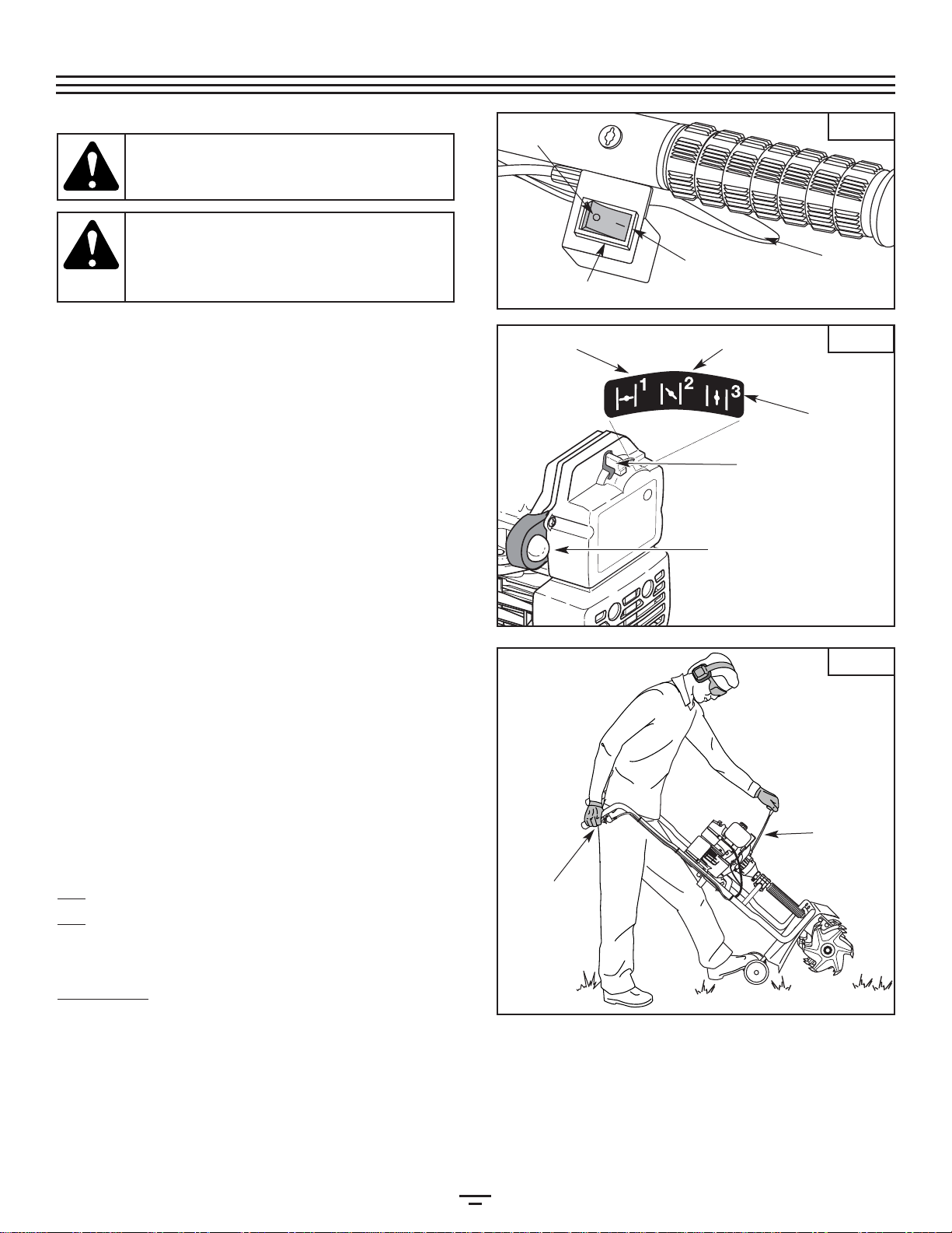
•Always hold the unit with both hands when operating.
Keepa firm grip on the handlebar grips.
•Keep hands, face and feet at a distance from all moving
parts. Do not touch or try to stop the tines when they are
rotating.Do not operate without guards in place.
•Do not touch the engine, muffler or gearbox. These parts
get extremely hot from operation. When turned off they
remainhot for a short time.
•Do not operate the engine faster than the speed needed
to do the job. Do not run the engine at high speed when
notin use.
•Always stop the engine during suspended or delayed
operation,or when you walk from one location to another.
•Stop the engine for maintenance, repair or to install or
remove the tines. To avoid injury, stop the unit and make
surethe tines no longer turn.
•The tines become very sharp from use. Always wear heavy
gloves when handling, removing, installing or cleaning the
tines.
•Use only Genuine Factory Parts™ replacement parts and
accessories for this unit. These are available from your
authorized service dealer. Use of any non original factory
parts or accessories could lead to serious injury to the user,
ordamage to the unit, and void your warranty.
•Keep the unit clean of vegetation and other materials. They
maybecome lodged between the tines and gearbox or guard.
•To reduce the risk of fire, replace a faulty muffler and spark
arrestor. Keep the engine and muffler free from grass,
leaves,excessive grease or carbon build up.
OTHER SAFETYWARNINGS
•Never store the unit, with fuel in the tank, inside a building
wherefumes may reach an open flame or spark.
•Allow the engine to cool before storing or transporting. Be
sureto secure the unit while transporting.
•Store the unit in a dry place, either locked up or up high to
prevent unauthorized use or damage. Keep out of the
reachof children.
•Clean the tines with a hose and water. Wipe the tines with
alight machine oil to prevent rust.
•Never douse or squirt the engine with water or any other liq-
uid. Keep handles dry, clean and free from debris. Clean after
each use, as described in the CleaningandStorage section.
•Keep these instructions. Refer to them often and use them
to instruct other users. If you loan someone this unit, also
loanthem these instructions.
SAVETHESE INSTRUCTIONS
• IMPORTANT SAFETY INFORMATION •
RULESFORSAFEOPERATION

5
SYMBOL MEANING
•SAFETY ALERT SYMBOL
Indicatesdanger, warning or caution.
Maybe used in conjunction with other
symbolsor pictographs.
•WARNING - READ
OPERATOR'S MANUAL
Readthe operator’s manual(s) and follow
allwarnings and safety instructions.
Failureto do so can result in serious
injuryto the operator and/or bystanders.
•WEAR EYE AND HEARING
PROTECTION
WARNING: Thrownobjects and loud
noisecan cause severe eye injury and
hearingloss. Wear eye protection
meetingANSI Z87.1 standards and ear
protectionwhen operating this unit. Use
afull face shield when needed.
•KEEP BYSTANDERS AWAY
WARNING: Keepall bystanders,
especiallychildren and pets, at least 50
feet(15 m) from the operating area.
•UNLEADED FUEL
Alwaysuse clean, fresh unleaded fuel.
•OIL
Referto operator's manual for the proper
typeof oil.
•THROWN OBJECTS AND ROTATING
CUTTER CAN CAUSE SEVERE
INJURY
WARNING: Donot operate without the
proper attachmentsand guards in place.
Keepaway from the rotating tines.
SYMBOL MEANING
•ON/OFF STOP CONTROL
ON/ START / RUN
•ON/OFF STOP CONTROL
OFFor STOP
•HOT SURFACEWARNING
Donot touch a hot muffler, gear housing
orcylinder. You may get burned. These
partsget extremely hot from operation.
Theyremain hot for a short time after the
unitis turned off.
• CHOKE CONTROL
1 • FULL choke position.
2 • PARTIAL choke position.
3 • RUN position.
•GARDEN CULTIVATORS – ROTATING
TINES CAN CAUSE SEVERE INJURY
WARNING: Stopthe engine and allow
thetines to stop before installing or
removingtines, or before cleaning or
performingany maintenance. Keep
handsand feet away from rotating tines.
•NO STEP
Alwayskeep proper footing and balance.
Donot overreach, take extra care when
workingon steep slopes or inclines.
•PLACE LEFT FOOT HERE
Avoidaccidental starting. Stand in the
startingposition whenever pulling the
starterrope. The operator and unit must
bein a stable position while starting.
123
SAFETY AND INTERNATIONAL SYMBOLS
Thisoperator's manual describes safety and international symbols and pictographs that may appear on this product.
Readthe operator's manual for complete safety, assembly, operating and maintenance and repair information.
RULESFORSAFEOPERATION

6
Tine Guard
Tines
Gearbox
Primer Bulb Choke Control
Air Filter/
Muffler Cover
Spark
Plug
Muffler
Fuel Cap
Throttle
Control
Starter Rope Grip
Handlebar
Wheel Bracket
Assembly
Shaft Tube Grip
Handgrip
Handgrip
On/Off Stop
Control
STOP/OFF (O)
START/ON (I)
Throttle
Cable and
Switch Wires
Handlebar
Knob
Handlebar
Knob
KNOWYOUR UNIT
Application:
•Cultivating sod and light to medium soil
•Cultivatingin gardenareas,aroundtrees,etc.
RULESFORSAFEOPERATION

7
ASSEMBLINGTHE UNIT
Beforeoperating, position the unit’s handlebars.
NOTE: You may also need to reposition the wheel
height before using the cultivator. Refer to the
AdjustingTineDepth section.
Beginby carefully unpacking the contents and making sure
thatnothing is damaged.
POSITIONINGTHE HANDLEBARS
1. Loosenthe two knobs on the inside of the handlebars
(Fig.1).
2. Withthe unit upright, swing the handlebars up into the
operatingposition (Fig. 1).
NOTE: Take care not to pinch the throttle cable or
switchwires when positioning the handlebar.
3. Tightenthe knobs to secure the handlebars in place.
NOTE: Donot over-tighten the knobs.
4. Readjustthe throttle cable and switch the wires so they
aresmooth and tight against the handlebar assembly.
Thiswill help prevent them from catching or snagging
duringnormal operation.
ADJUSTINGTHE HANDLEBAR HEIGHT
1. Removethe knobs and mounting bolts and reinstall
themthrough either the top or bottom holes in the
handlebarassembly (Fig. 2) in order to adjust the height
ofthe handlebars.
2. Besure to tighten the knobs to secure the handlebars in
place.
Handlebar
Knobs Handlebar
Knobs
Handlebar
Knob
Handlebars
Washer
Bottom Hole
Top Hole
Bolt
INSTALLINGTHE WHEEL BRACKET ASSEMBLY
Ifthe wheelbracket assembly is notinstalled,or if you
ever need to remove or reinstall it,follow the ensuing
instructions.
1. Withthe unit on its side, place the wheel bracket
assemblyon the underside of the tine guard (Fig. 3).
2. Installa carriage bolt through each of the slotted holes in
thewheel bracket and into the tine guard.
3. Onthe TOP side of the tine guard, install a lock washer
anda wing nut onto each of the bolts (Fig. 3).
4. Makesure the square shoulder of the bolts is pushed
throughthe slotted holes in the wheel bracket. Tighten
thewing nuts (Fig. 4).
NOTE: Do not over-tighten the wing nuts. Loosen the
wingnuts to adjust wheel height.
Wing Nut &
Lock Washer
Tine
Guard
Wheel
Bracket
Assembly
WARNING: To prevent serious personal injury,
the wheel bracket assembly must be installed
whenoperating the unit.
WARNING: To avoid injury from the tines, wear
heavy gloves and a long sleeve shirt when
installingthe wheel bracket assembly.
Fig.1
Fig.4
Fig.3
Fig.2
ASSEMBLYINSTRUCTIONS

8
NOTE: Dispose of the old fuel/oil mix in accordance to
Federal,state, and local regulations.
OIL AND FUEL MIXING INSTRUCTIONS
Oldand/or improperly mixed fuel are the main reasons for
theunit not running properly. Be sure to use fresh, clean
unleadedfuel. Follow the instructions carefully for the proper
fuel/oilmixture.
Definition of Blended Fuels
Today'sfuels are often a blend of gasoline and oxygenates
suchas ethanol, methanol, or MTBE (ether). Alcohol-blended
fuelabsorbs water. As little as 1% water in the fuel can make
fueland oil separate. It forms acids when stored. When using
alcohol-blendedfuel, use fresh fuel (less than 60 days old).
Using Blended Fuels
Ifyou choose to use a blended fuel, or its use is unavoidable,
followrecommended precautions:
•Alwaysuse fresh fuel mix per your operator's manual
•Alwaysagitate the fuel mix before fueling the unit
•Drainthe tank and run the engine dry before storing the
unit
Using Fuel Additives
Thebottle of 2-cycle oil that came with your unit contains a
fueladditive which will help inhibit corrosion and minimize
theformation of gum deposits. It is recommended that you
useour 2-cycle oil with this unit.
Ifunavailable, use a good 2-cycle oil designed for air-cooled
enginesalong with a fuel additive, such as STA-BIL® Gas
Stabilizeror an equivalent. Add 0.8 oz. (23 ml.) of fuel
additiveper gallon of fuel according to the instructions on
thecontainer. NEVER add fuel additives directly to the unit's
fueltank.
Thoroughlymix the proper ratioof2-cycleengineoilwith
unleadedgasoline in a separatefuelcan.Usea40:1fuel/oilratio.
Donot mix them directlyintheenginefueltank.Seethe
followingtable for specific gasandoilmixingratios.
NOTE: One gallon (3.8 liters) of unleaded gasoline
mixed with one 3.2 fl.oz. (95 ml.) bottle of
2-CycleOil makesa 40:1fuel/oil ratio.
CAUTION: For proper engine operation and
maximum reliability, pay strict attention to the
oil and fuel mixing instructions on the 2-cycle oil
container. Using improperly mixed fuel can
severelydamage theengine.
WARNING Add fuel in a clean, well ventilated
area outdoors. Wipe up any spilled fuel imme-
diately. Avoid creating a source of ignition for
spilled fuel. Do not start the engine until fuel
vaporsdissipate
WARNING: Remove fuel cap slowly to avoid
injury from fuel spray. Never operate the unit
withoutthefuel capsecurelyin place.
WARNING: Gasoline is extremely flammable.
Ignited vapors may explode. Always stop the
engine and allow it to cool before filling the fuel
tank. Do not smoke while filling the tank. Keep
sparksand open flames at a distance from the area.
UNLEADED GAS 2 CYCLE OIL
1 US. GALLON
(3.8 LITERS) 3.2 FL OZs.
(95 ml)
1 LITER 25 ml
+
MIXING RATIO = 40 : 1
FILLINGTHE FUELTANK
Makesure the cultivator is in a horizontal position when
fillingor adding fuel to the tank.
Fig.5
OIL&FUELINFORMATION

9
Starter
Rope
Throttle
Control
STARTING INSTRUCTIONS
1. Mixgas with oil. Fill fuel tank with fuel/oil mixture. Refer
toOilandFuelMixingInstructions.
2. Make sure the On/Off Stop Control in the ON [I]position
(Fig. 6).
3. Place the choke lever in Position 1(Fig.7).
4. Fully press and release the primer bulb 10 times, slowly.
Some amount of fuel should be visible in the primer
bulb and fuel lines (Fig. 7). If you can’t see fuel in the
bulb, press and release the bulb as many times as it
takes before you can see fuel in it.
5. Standbetween the handlebars and support the unit by
placingyour left foot on the wheel bracket assembly and
grippingthe handlebar grip with your right hand (Fig. 8).
NOTE: Tiltthe unit back slightly to bring the tines off the
groundwhen starting.
6. Whilesqueezing the throttle control to the wide open
(fullthrottle) position, grasp the starter rope grip with
your left hand. Pull the starterropeouta short distance,
untilyoufeel someresistance.This isusuallyaround 2-4
inches.Thenpull theropesmoothly andbriskly.Repeat
this5times.
7. Move the choke lever to Position 2.
8. While squeezing the throttle control, pull the starter
rope in the same manner as explained in Step 6. Pull 1 to
3 times to start the engine.
9. Keep the throttle squeezed and allow the engine to
warm up for 15 to 30 seconds.
10. Place the choke lever in Position 3. Release the throttle
control to the idle position and begin operation.
IF... The engine does not start, go back to step 3.
IF... The engine fails to start after a few attempts, place the
choke lever in Position 3and squeeze the throttle
control. Pull the starter rope briskly 3 to 8 times. The
engine should start. If not, repeat.
IFWARM... If the engine is already warm, make sure the
On/Off Stop control is in the ON position and start the
unit with the choke lever in Position 2. After the unit
starts, move the choke lever to Position 3. STOPPING INSTRUCTIONS
1. Releaseyour hand from the throttle control (Fig. 8).
Allowthe engine to cool down by idling.
2. Putthe On/Off Stop Control in the STOP (O) position
(Fig.6).
Start / Stop Control START (I)
STOP (O)
Throttle Control
WARNING: Operate this unit only in a well- ven-
tilated outdoor area. Carbon monoxide exhaust
fumescan be lethal in a confined area
.
WARNING: Avoid accidental starting. Make sure
you are in the starting position when pulling the
starter rope (Fig. 8).
To avoid serious injury, the
operator and unit must be in a stable position
whilestarting.
Fig.8
Fig.7
Fig.6
STARTING/STOPPINGINSTRUCTIONS
Choke Lever
Position 1
Primer Bulb
Position 3
Position 2

10
TRANSPORTINGTHE UNIT
1. Stopthe engine.
2. Slidethe wheel bracket assembly all the way down.
3. Tiltthe unit back until the tines clear the ground.
4. Pushor pull the unit to the next location.
OPERATINGTIPS
1. Movethe cultivator to the work area prior to starting the
engine.Transport the cultivator by pushing it on its wheels.
2. Start the unit as described in the StartingInstructions.
3. Withthe engine running and the tines off the ground,
depressthe throttle control to increase the engine speed.
4. Holdingboth of the handlebar grips firmly, slowly lower
thecultivator until the tines make contact with the
ground(Fig. 9).
5. Ascultivating action begins, pull back on the cultivator
sothat the tines can penetrate the ground.
6. Oncethe ground has been broken, continue at a
moderatepace until you are familiar with the controls
andthe handling of the cultivator.
7. Pullthe cultivator backwards to improve the depth of
cultivationand reduce your effort.
8. Ifthe tines are digging too deep or not deep enough,
adjust them according to AdjustingTineDepth.
ADJUSTINGTINE DEPTH
Tineadjustment will vary depending on the type of soil being
cultivatedand how it will be used. Generally, adjusting the tines
tobreak the soil 4 to 6 inches is recommended for most
gardens.Adjust the tines as follows:
1. Stopthe engine and disconnect the spark plug wire.
2. Loosen(do not remove) the two wing nuts on the tine
guard(Fig. 10).
3. Slidethe wheel bracket assembly down for shallower
penetration,and up for deeper tine penetration.
4. Oncethe tines are in the desired position, tighten the
wingnuts, making sure that the carriage bolts are seated
properlythrough the bracket.
5. Ifthe tine depth is incorrect, repeat steps 2 to 4.
6. Reconnectthe spark plug wire and continue use.
Down
Up
WARNING: Always wear eye, hearing, foot and
body protection to reduce the risk of injury
whenoperating this unit.
WARNING: To prevent serious personal injury,
use extreme caution when reversing or pulling
theunit towards you.
WARNING: To prevent serious personal injury,
never pick-up or carry the unit while the engine
isrunning.
WARNING: To prevent serious personal injury,
always stop the engine when operation is
delayed or when transporting the unit from one
locationto another.
Fig.10
Fig.9
OPERATINGINSTRUCTIONS

11
Clevis Pin Clip
Felt
Cushion
Shaft
Felt
Washer
Tine Hubs
Stagger Tips
R
R
L
L
Clevis Pin
TINE REMOVAL AND REPLACEMENT
Replaceall four (4) tines at the same time, because they will
wearevenly through normal use. Work on one side at a time.
1. Putthe On/Off Stop Control in the STOP (O) position
anddisconnect the spark plug wire.
2. Removethe clevis pin clips and clevis pins (Fig. 11).
3. Removethe tines and felt washers from the shaft.
4. Cleanand oil the shaft.
5. Thetines are stamped with the letter "R" or "L" to
identifiedtheir position on each side of the gearbox
whenfacing the front of the unit.
6. Replacethe tines and felt washers onto the shaft with
thehubs on the tines facing each other.
MAINTENANCE SCHEDULE
Performthese requiredmaintenance proceduresat the
frequencystated inthe table.These procedures should also
bea partof anyseasonal tune-up.
NOTE: Some maintenance procedures may require
special tools or skills. If you are unsure about
these procedures take your unit to any non-
road engine repair establishment, individual or
authorizedservice dealer.
NOTE:
Maintenance, replacement, or repair of the emis-
sion control devices and system may be performed
by any non-road engine repair establishment, indi-
vidualor authorized service dealer.
In order to assure peak performance of your engine, inspec-
tion of the engine exhaust port may be necessary after 50
hours of operation. If you notice lost RPM, poor performance
or general lack of acceleration, this service may be required. If
you feel your engine is in need of this inspection, refer service
to any non-road engine repair establishment, individual or
authorized service dealer for repair. DO NOT attempt to per-
form this process yourself as engine damage may result from
contaminantsinvolved in the cleaning process for the port.
FREQUENCY MAINTENANCE REQUIRED REFER TO
Beforestarting engine Fill fuel tank with fresh fuel mix Page8
Every10 hours Clean and re-oil air filter Page12
Every25 hours Check and clean spark arrestor
Checkspark plug condition and gap Page 12
Page13
Every50 hours Inspect exhaust port and spark arrestor screen for clogging or
obstructionto assure maximum performance levels Page 12
WARNING: To prevent serious injury, never per-
form maintenance or repairs with unit running.
Always service and repair a cool unit. Disconnect
the spark plug wire to ensure that the unit can-
notstart.
7. Beforeyou reinstall the clevis pins and pin clips, ensure
thatthe tips on the tines are staggered when compared
toeach other (Fig. 12).
8. Repeatthis procedure on the opposite side.
NOTE: Wheninstalled correctly, there will be an "R" and "L"
tineon both the sides of the gearbox and the tips of
thetines. These letters will line up in the same
directionfor each side. It is important that the tines
areinstalled correctly.
WARNING:
To prevent serious personal injury,
always wear heavy gloves when
handling the
tines.
Fig.12
Fig.11
MAINTENANCE& REPAIRINSTRUCTIONS

12
Cleaning the Air Filter
Cleanand re-oil the air filter every 10 hours of operation. It is
animportant item to maintain. Failure to maintain the air
filterwill VOID the warranty.
1. Removethe air filter/muffler cover. Refer to the
RemovingtheAirfilter/MufflerCover section.
2. Removethe air filter from inside the air filter/muffler
cover(Fig. 14).
3. Washthe filter in detergent and water (Fig. 14). Rinse the
filterthoroughly. Squeeze out excess water. Allow it to
drycompletely.
4. Applyenough SAE 30 oil to lightly coat the filter (Fig. 15).
5. Squeezethe filter to spread and remove extra oil (Fig. 15).
6. Replacethe air filter inside the muffler cover (Fig. 14).
NOTE:
Operating the unit without the air filter and cover
assemblywillVOID thewarranty
.
Reinstalling the Air filter/Muffler Cover
1. Placethe air filter/muffler cover over the back of the
carburetorand muffler.
NOTE:
The choke control must be in
Position 2 (Fig. 13)
toremove the air filter/ muffler cover.
Choke Control
Screws Screws
Position 2
2. Insertthe four (4) screws into the holes in the air filter/
mufflercover (Fig. 13) and tighten. Use a flat blade or # T20
Torxbit screwdriver. Do not over tighten. Do not force.
Air Filter
Inside Muffler
Cover
AIR FILTER MAINTENANCE
Removing the Air Filter/Muffler Cover
1. Placethe choke control in
Position2
.
NOTE:
The choke control must be in
Position 2 (Fig. 13)
toremove the air filter/ muffler cover.
2. Removethe four (4) screws securing the air filter/muffler
cover(Fig. 13). Use a flat blade or # T20 Torx bit
screwdriver.
3. Pullthe cover from the engine. Do not force.
WARNING: To avoid serious personal injury,
always turn your unit off and allow it to cool
beforeyou clean or service it.
SPARK ARRESTOR MAINTENANCE
1. Remove the air filter/muffler cover. Refer to Removingthe
AirFilter/MufflerCover.
2. Locatethe muffler front and the two (2) bolts securing it
tothe engine (Fig. 16). Remove the two (2) bolts using a
flatbladescrewdriver or 5/16-inch socket or nut driver.
Pullthe muffler off of the engine.
3. Turnthe muffler over to the back side and locate the
exhaustgasket. Remove the muffler gasket from the
muffler(Fig. 16).
NOTE:
Ifthe exhaust gasket is torn or damaged, replace it with
anewgasket beforeyou
reassemblethemuffler.
4. Usinga small flatblade screwdriver, carefully pry up the
sparkarrestor from the recessed hole (Fig. 17). Remove
thespark arrestor from the muffler.
5. Cleanthe spark arrestor with a wire brush. Replace it if it is
damagedor if it can’t be cleaned thoroughly (Fig. 17).
6. Reinstallthe spark arrestor by pressing it into the
recessedhole on the muffler's back side. Make sure it fits
tightlyagainst the muffler and is not raised up.
7. Placethe exhaust gasket against muffler's back side.
Alignthe gasket bolt holes with the bolt holes in the
muffler.While holding exhaust gasket in place, insert the
boltsinto the muffler's front side (Fig. 16).
Fig.15
Fig.14
Fig.13
MAINTENANCE& REPAIRINSTRUCTIONS

13
REPLACINGTHE SPARK PLUG
Usea Champion RDJ7Y spark plug (or equivalent). The
correctair gap is 0.020 in. (0.5 mm). Remove the plug after
every25 hours of operation to check its condition.
1. Stopthe engine and allow it to cool. Grasp the plug wire
firmlyand pull the cap from the spark plug.
2. Cleandirt from around the spark plug. Remove the spark
plugfrom the cylinder head by turning a 5/8 in. socket
counterclockwise.
NOTE: Replacea cracked, fouled or dirty spark plug.
3. Setthe air gap at 0.020 in. (0.5 mm) using a feeler gauge
(Fig.19).
Adjust Idle Speed Adjuster
Ifafter checking the fuel mixture and cleaning the air filter
theengine still will not idle, adjust the idle speed screw as
follows:
1. Startthe engine and let it run for about 2-3 minutes at a
highspeed (full throttle) to warm up. Refer to the
Starting/StoppingInstructions.
NOTE: Ensure the tines are not in contact with the
groundwhen adjusting the idle.
2. Releasethe throttle control and let the engine idle. If the
enginestops, insert a small phillips or flat blade
screwdriver into the hole in the muffler cover (Fig. 18).
Turn the idle speed screw clockwise 1/8of a turn at a
time(as needed) until the engine idles smoothly.
NOTE:
Thetines should not rotate during engine idle.
3. Ifthe tines rotate when the engine idles, turn the idle
speed screw counterclockwise 1/8 of a turn at a time
(as needed), to reduce idle speed.
Checkingthe fuel mixture, cleaning the air filter, and
adjustingthe idle speed screw should solve most engine
problems.If not and all the following are true:
•Theengine will not idle
•Theengine hesitates or stalls on acceleration
•Thereis a loss of engine power
Havethe carburetor adjusted by an authorized service dealer.
Idle Speed Adjuster
Muffler - Front Side Muffler - Back Side
Bolts
Exhaust Gasket
Spark
Arrestor
Muffler - Back Side
Spark Arrestor Flatblade
Screwdriver
Spark Arrestor
WARNING:
If the muffler is not tightened
securely
,
it could fall off causing damage to the unit and
possibleserious personal injury.
CAUTION: Do not sand blast, scrape or clean
electrodes. Grit in the engine could damage the
cylinder.
WARNING: The unit may still run during idle
speed adjustments. Wear protective clothing
and observe all safety instructions to prevent
seriouspersonal injury.
CARBURETOR ADJUSTMENTS
Theengine’s idle speed adjuster is adjustable through the air
filter/mufflercover (Fig 18).
NOTE:
Careless adjustment
s can seriously damage your
unit. An authorized service dealer should make
carburetoradjustments.
Check Fuel Mixture
Oldand/or improperly mixed fuel is usually the reason for
theunit not running properly. Drain and refill the tank with
fresh,properly mixed fuel prior to making any adjustments.
Refer to OilandFuelInformation.
Clean Air Filter
Thecondition of the air filter is important to the operation of
theunit. A dirty air filter will restrict air flow and change the
air/fuelmixture. This is often mistaken for an out of
adjustmentcarburetor. Check the condition of the air filter
before adjusting the idle speed adjuster. Refer to AirFilter
Maintenance.
8. Placethe muffler (with the exhaust gasket in place and bolts
inserted),against the engine, aligning the bolt holes.
Tightenthe bolts to secure the muffler to the engine.
If
usinga torque wrench, torque to:
80-90 in.•lb. (9-10.2 N•m)
9. Reinstallthe air filter/muffler cover.
Fig.16
Fig.18
Fig.17
MAINTENANCE& REPAIRINSTRUCTIONS

14
Handlebar Knobs
Shaft Tube
Grip
TRANSPORTING
•Allowthe engine to cool before transporting.
•Securethe unit while transporting.
•Drainthe fuel tank before transporting.
•Tightenfuel cap before transporting.
MOVINGTHE UNIT
1. Allowthe unit to cool before moving.
2. Loosenthe knobs on the handlebar.
3. Foldthe handlebars down as shown (Fig. 20).
ACCESSORIES/REPLACEMENT PARTS
2-CycleOil . . . . . . . . . . . . . . . . . . . . . . . . . . . . . . .. . . . . . . . . . 147543
SparkPlug . . . . . . . . . . . . . . . . . . . . . . . . . . . . . . .. . . . . . . . . . 610311
FuelCap . . . . . . . . . . . . . . . . . . . . . . . . . . . . . . .. . . . . . . . . . . . 180000
Tine(L) (Left Side Outer or Right Side Inner) . . . . . . . . .182729
Tine(R) (Right Side Outer or Left Side Inner) . . . . . . . . .182730
ClevisPin withClip . . .. .. .. .. .. . . .. . .. .. .. .. .. .. .. .. .147473
4. Eithercarry the unit by the shaft tube grip or grasp the
centerof the handlebar to use it as a carrying handle
(Fig.21).
5. Afterthe unit has been moved, reposition the
handlebarsand continue operation.
CLEANINGTHE UNIT
•Usea small brush to clean off the outside of the unit and
tokeep the air vents free of obstructions.
•Donot use strong detergents or petroleum based
cleaners,like kerosene. Some household cleaners
containaromatic oils such as pine and lemon that can
damagethe plastic housings or handles. Wipe off any
moisturewith a soft cloth.
STORAGE
•Neverstore a fueled unit where fumes may reach an
openflame or spark.
•Allowthe engine to cool before storing.
•Storethe unit in a locked up area to prevent
unauthorizeduse or damage.
•Storethe unit in a dry, well-ventilated area.
•Storethe unit out of the reach of children.
LONGTERM STORAGE
Ifyou plan to store the unit for an extended time:
1. Drainall fuel from the fuel tank into a container. Do not
usefuel that has been stored for more than 60 days.
Disposeof the old fuel in accordance to local regulations.
2. Startthe engine and allow it to run until it stalls. This
ensuresthat all fuel has been drained from the carburetor.
3. Allowthe engine to cool. Remove the spark plug and put
1oz. (30 ml) of high quality motor oil into the cylinder.
Pullthe starter rope slowly to distribute the oil. Reinstall
thespark plug.
NOTE: Remove the spark plug and drain all of the oil
from the cylinder before attempting to start the
unitafter storage.
4. Thoroughlyclean the unit and inspect for any loose or
damagedparts. Repair or replace damaged parts and
tightenloose screws, nuts or bolts. The unit is ready for
storage.
WARNING: To avoid serious personal injury,
always turn the off and allow it to cool before
youclean orservice it.
4. Installa correctly gapped spark plug in the cylinder head.
Tightenby turning the 5/8 in. socket clockwise until snug.
Ifusing a torque wrench torque to:
110-120 in.•lb. (12.3-13.5 N•m)
Donot over tighten.
0.020 in.
(0.5 mm)
Fig.21
Fig.20
Fig.19
MAINTENANCE& REPAIRINSTRUCTIONS

15
CAUSE ACTION
On/OffStop Control in the STOP position Turn the On/Off Stop Control to START
Emptyfuel tank Fill fuel tank
Primerbulb wasn't pressed enough Press primer bulb fully and slowly 10 times
Engineflooded Use starting procedure with choke control in Position 2
Oldor improperly mixed fuel Drain fuel tank / Add fresh fuel mixture
Fouledspark plug Replace or clean the spark plug
Pluggedspark arrestor Clean or replace spark arrestor
ENGINEWILL NOT START
CAUSE ACTION
AirFilter is Plugged Replace or clean the air filter
Oldor improperly mixed fuel Drain fuel tank / Add fresh fuel mixture
Impropercarburetor adjustment Adjust according to the CarburetorAdjustmentssection
ENGINEWILL NOT IDLE
CAUSE ACTION
Oldor improperly mixed fuel Drain fuel tank / Add fresh fuel mixture
Impropercarburetor adjustment Take to an authorized service dealer for a carburetor adjustment
Cultivatortines bound with dirt or grass Stop the unit, switch the On/Off Stop Control to STOP,
cleanand remove any debris binding the tine
Dirtyair filter Clean or replace the air filter
Pluggedspark arrestor Clean or replace spark arrestor
ENGINEWILL NOT ACCELERATE
CAUSE ACTION
Oldor improperly mixed fuel Drain fuel tank / Add fresh fuel mixture
Impropercarburetor adjustment Take to an authorized service dealer for a carburetor adjustment
Fouledspark plug Replace or clean the spark plug
Pluggedspark arrestor Clean or replace spark arrestor
ENGINE LACKS POWER OR STALLSWHEN UNDER LOAD
TROUBLESHOOTING

16
ENGINE
EngineType...................................................................................................................................................................................... Air-Cooled,2-Cycle
Displacement............................................................................................................................................................................................................. 31 cc
Idle Speed RPM.................................................................................................................................................................................. 2,800 - 3,600 rpm
OperatingRPM.............................................................................................................................................................................................. 7,700+ rpm
ClutchType...................................................................................................................................................................................................... Centrifugal
IgnitionType...................................................................................................................................................................................................... Electronic
On/Off Stop Control............................................................................................................................................................................... Rocker Switch
Spark Plug Gap............................................................................................................................................................................. 0.020inch (0.5 mm)
Lubrication............................................................................................................................................................................................. Fuel/Oil Mixture
Fuel/Oil Ratio............................................................................................................................................................................................................... 40:1
Carburetor............................................................................................................................................................................... Diaphragm,All-Position
Starter............................................................................................................................................................................................................ Auto Rewind
Muffler................................................................................................................................................................................................ Baffled with Guard
Throttle........................................................................................................................................................................................................ Spring Return
FuelTank Capacity......................................................................................................................................................................... 14 ounces (415 ml)
DRIVE SHAFT AND CULTIVATOR
DriveShaftTube.............................................................................................................................................................................................. SteelTube
Throttle Control................................................................................................................................................................................ Finger-TipTrigger
Cultivating PathWidth (Maximum)....................................................................................................................................... 9inches (22.86 cm)
Cultivating Depth(Maximum)................................................................................................................................................. 6inches(15.24 cm)
Approximate Unit Weight (no fuel) .................................................................................................................................................... 26 lb.(12 kg)
SPECIFICATIONS

EPA Emission ControlWarranty Statement
YourWarranty Rights and Obligations
TheEnvironmental Protection Agency and Troy-Bilt LLC are pleased to explain the emission control system warranty on your
2002and later small off-road engine. New small off-road engines must be designed, built and equipped to meet stringent anti-
smogstandards. Bolens must warrant the emission control system on your small off-road engine for the periods of time listed
belowprovided there has been no abuse, neglect or improper maintenance of your small off-road engine.
Youremission control system may include parts such as the carburetor or fuel-injected system, the ignition system, and catalytic
converter.Also included may be hoses, belts, connectors and other emission-related assemblies.
Wherea warrantable condition exists, Bolens will repair your small off-road engine at no cost to you including diagnosis, parts
andlabor.
The2002 and later small off-road engines are warranted for two years. If any emission-related part on your engine is defective,
thepart will be repaired or replaced my Bolens.
OwnersWarranty Responsibilities
•As the small off-road engine owner, you are responsible for the performance of the required maintenance listed in your
operator’smanual. Bolens recommends that you retain all receipts covering maintenance on your small off-road engine, but
Bolenscannot deny warranty solely for the lack of receipts or for your failure to ensure the performance of all scheduled
maintenance.
•As the small off-road engine owner, you however should be aware that Bolens may deny you warranty coverage if your small
off-roadengine or a part has failed due to abuse, neglect, improper maintenance or unapproved modifications.
•You are responsible for presenting your small off-road engine to a Bolens Authorized Service Center as soon as a problem exists.
Thewarranty repairs should be completed in a reasonable amount of time, not to exceed 30 days.
Ifyou have any questions regarding your warranty rights and responsibilities, you should call 1-800-520-5520.
Manufacturer’sWarranty Coverage
•The warranty period begins on the date the engine or equipment is delivered to the retail purchaser.
•The manufacturer warrants to the initial owner and each subsequent purchaser, that the engine is free from defects in material
andworkmanship which cause the failure of a warranted part for a period of two years.
•Repair or replacement of warranted part will be performed at no charge to the owner at an Authorized Bolens Service Center.
Forthe nearest location please contact Bolens at: 1-800-520-5520.
•Any warranted part which is not scheduled for replacement, as required maintenance or which is scheduled for only for regular
inspectionto the effect of “Repair or Replace as Necessary” is warranted for the warranty period. Any warranted part which is
scheduledfor replacement as required maintenance will be warranted for the period of time up to the first scheduled
replacementpoint for that part.
•The owner will not be charged for diagnostic labor which leads to the determination that a warranted part is defective, if the
diagnosticwork is performed at an Authorized Bolens Service Center.
•The manufacturer is liable for damages to other engine components caused by the failure of a warranted part still under
warranty.
•Failures caused by abuse, neglect or improper maintenance are not covered under warranty.
•The use of add-on or modified parts can be grounds for disallowing a warranty claim. The manufacturer is not liable to cover
failuresof warranted parts caused by the use of add-on or modified parts.
• In order to file a claim, go to your nearest Authorized Bolens Service Center. Warranty services or repairs will be provided at all
AuthorizedBolens Service Centers.
•Any manufacturer approved replacement part may be used in the performance of any warranty maintenance or repair of
emissionrelated parts and will be provided without charge to the owner. Any replacement part that is equivalent in performance
ordurability may be used in non-warranty maintenance or repair and will not reduce the warranty obligations of the
manufacturer
•The following components are included in the emission related warranty of the engine, air filter, carburetor, primer, fuel lines,
fuelpick up/ fuel filter, ignition module, spark plug and muffler.

SAVETHESE INSTRUCTIONS FOR FUTURE REFERENCE
FOR QUESTIONS CALL 1-800-520-5520
OPERATOR’S MANUAL PART NO. 769-00488A 11/03
PRINTED IN U.S.A.
MANUFACTURER’S LIMITEDWARRANTYFOR:
No implied warranty, including any implied warranty of
merchantability or fitness for a particular purpose,
applies after the applicable period of express written
warranty above as to the parts as identified. No other
express warranty or guaranty, whether written or oral,
except as mentioned above, given by any person or
entity, including a dealer or retailer, with respect to any
product shall bind Troy-Bilt LLC. During the period of
the Warranty, the exclusive remedy is repair or
replacement of the product as set forth above. (Some
states do not allow limitations on how long an implied warranty
lasts,so the above limitation may not apply to you.)
The provisions as set forth in this Warranty provide the
sole and exclusive remedy arising from the sales. Troy-Bilt
LLC shall not be liable for incidental or consequential loss
or damages including, without limitation, expenses
incurred for substitute or replacement lawn care services,
for transportation or for related expenses, or for rental
expenses to temporarily replace a warranted product.
(Some states do not allow limitations on how long an implied
warrantylasts, so the above limitation may not apply to you.)
In no event shall recovery of any kind be greater than the
amount of the purchase price of the product sold.
Alteration of the safety features of the product shall void
this Warranty. You assume the risk and liability for loss,
damage, or injury to you and your property and/or to others
and their property arising out of the use or misuse or inabili-
tyto use the product.
This limited warranty shall not extend to anyone other than
the original purchaser, original lessee or the person for
whomit was purchased as a gift.
How State Law Relates to this Warranty:This warranty
gives you specific legal rights, and you may also have other
rightswhich vary from state to state.
To locate your nearest service dealer dial 1-800-520-5520.
TROY-BILT LLC
POBox 361131
Cleveland,OH 44136-0019U.S.A.
The limited warranty set forth below is given by Troy-Bilt
LLC with respect with new merchandise purchased and
usedin the United States, its possessions and territories.
Troy-Bilt warrants this product against defects in material
and workmanship for a period of two (2) years commencing
on the date of original purchase and will, at its option, repair
or replace, free of charge, any part found to be defective in
material or workmanship. This limited warranty shall only
apply if this product has been operated and maintained in
accordance with the Operator’s Manual furnished with the
product, and has not been subject to misuse, abuse, com-
mercial use, neglect, accident, improper maintenance, alter-
ation, vandalism, theft, fire, water or damage because of
other peril or natural disaster. Damage resulting from the
installation or use of any accessory or attachment not
approved by Troy-Bilt for use with the product(s) covered by
thismanual will void your warranty as to any resulting damage.
This warranty is limited to ninety (90) days from the date of
original retail purchase for any Bolens product that is used
for rental or commercial purposes, or any other income-pro-
ducingpurpose.
HOW TO OBTAIN SERVICE: Warranty service is available,
WITH PROOF OF PURCHASE THROUGH YOUR LOCAL
AUTHORIZED SERVICE DEALER. To locate the dealer in your
area, please check for a listing in the Yellow Pages or con-
tact the Customer Service Department of Troy-Bilt LLC by
calling 1-800-520-5520 or writing to PO Box 361131,
Cleveland, Ohio 44136-0019. No product returned directly
to the factory will be accepted unless prior written permis-
sion has been extended by the Customer Service
Departmentof Troy-Bilt LLC.
This limited warranty does not provide coverage in the
following cases:
A.Tune-ups - Spark Plugs, Carburetor Adjustments, Filters
B.Wear items - Bump Knobs, Outer Spools,Cutting Line,
InnerReels, Starter Pulley, Starter Ropes, Drive Belts
C.Troy-Bilt does not extend any warranty for products
soldor exported outside of the United States of
America,its possessions and territories, except those
soldthrough Troy-Bilt’s authorized channels of export
distribution.
Trot-Bilt reserves the right to change or improve the design of
any Bolens Product without assuming any obligation to modify
anyproduct previously manufactured.

Manuelde
L’utilisateur
CultivateurdeJardinà2-temps
ModèleBL410
Depuisqu’elleacommencéàfabriquerdes
outilsdejardinen1850,lasociétéBolensest
connuepourladurabilitéetlafiabilitédeses
produits.Bolens aperpétuécettetradition
dansl’industriedesoutilsmotorisésd’extérieur
lorsqu’elleaconçuetconstruitlepremier
tracteurdejardinmotorisé.
Denosjourslesamateursdejardinagedu
paystoutentiercomptentsurBolenspour
leurfournirdesoutilsmotorisésdurableset
fiablesàdesprixabordables.

S/N : ITEM :
MODEL :
Numéro de modèle
Numéro de série Numéro de pièce mère
F2
TABLE DES MATIÈRES
Servicetechnique . . . . . . . . . . . . . . . . . . . . . . . . . . . . . . .. . . . . .2
Consignesde sécurité . . . . . . . . . . . . . . . . . . . . . . . . . . . . . .. . .3
Familiarisez-vousavec votre appareil . . . . . . . . . . . . . . . . . .6
Instructionsde montage . . . . . . . . . . . . . . . . . . . . . . . . . . . . . .7
Informationssur l'huile et le carburant . . . . . . . . . . . . . . . . .8
Instructionsde démarrage et d'arrêt . . . . . . . . . . . . . . . . . . .9
Moded'emploi . . . . . . . . . . . . . . . . . . . . . . . . . . . . . . .. . . . . . .10
Entretienet réparations . . . . . . . . . . . . . . . . . . . . . . . . . . . . . .11
Accessoires/piècesde rechange . . . . . . . . . . . . . . . . . . . . . .14
Nettoyageet entreposage . . . . . . . . . . . . . . . . . . . . . . . . . . .14
Caractéristiques . .. .. .. .. .. .. .. .. .. .. .. .. .. .. .. .. .. .. .15
Tableaude dépannage . . . . . . . . . . . . . . . . . . . . . . . . . . . . . ..16
Garantie .. . . . . . . . . . . . . . . . . . . . . . . . . . . . . . .. . . . . . . . . . . . .18
Liste despièces . .. .. . .Intérieurede laCouverture Arrière
Prenezsoin de lire et de bien comprendre ce manuel avant
dedémarrer ou de faire fonctionner cet équipement.
CEPRODUIT EST COUVERT PAR UN OU PLUSIEURS BREVETS
AMÉRICAINS,ET D’AUTRES SONT EN INSTANCE
TOUS NOS REMERCIEMENTS
Nousvous remercions d'avoir acheté ce produit de qualité.
Cetoutil mécanique de plein air moderne est conçu pour
vousrendre service pendant longtemps. Il vous sauvera
beaucoupde temps comme vous pourrez vous en rendre
compte.Ce manuel de l'utilisateur comporte un mode
d'emploifacile à comprendre. Prenez soin de lire le manuel
aucomplet et suivez toutes ses instructions à la lettre afin de
conservervotre nouvel outil mécanique de plein air en
excellentétat de fonctionnement.
RÉFÉRENCES,ILLUSTRATIONS ET SPÉCIFICATIONS
RELATIVES AU PRODUIT
Toutesles informations, illustrations et spécifications
contenuesdans ce manuel tiennent compte des dernières
informationstechniques disponibles au moment de mettre
souspresse. Nous nous réservons le droit d'y apporter des
modificationsà tout moment, sans préavis.
Copyright©2003 MTD Southwest, Inc.Tous droits réservés.
NFORMATIONS D’ENTRETIEN
Toutentretien effectué sur cet appareil pendant et après la
périodede garantie doit être fait par un concessionnaire
agrééuniquement. Obtenez la liste des concessionnaires
agréés appelez le 1-800-520-5520.
NERETOURNEZ PAS L'APPAREIL AU DÉTAILLANT CHEZ QUI
VOUSL'AVEZ ACHETÉ. TOUT SERVICE SOUS GARANTIE
NÉCESSITEUNE PREUVE D'ACHAT.
Avantd'assembler votre nouvel équipement, repérez la
plaquesignalétique de l'appareil et copiez ses informations
dansl'espace ci-dessous. Ces informations sont essentielles si
vousdésirez obtenir de l'aide auprès de notre service
techniqueou d'un distributeur agréé. Un exemple de plaque
signalétiqueest présenté ci-dessous.
INTRODUCTION
Copiez le numéro
de modèle / pièce ici :
Copiez le numéro de
modèle / pièce mère ici :
AVERTISSEMENT
LES GAZ D'ÉCHAPPEMENT DU MOTEUR DE CET
APPAREIL CONTIENNENT DES PRODUITS CHIMIQUES
CONSIDÉRÉS PAR L'ÉTAT DE CALIFORNIE COMME
POUVANT CAUSER LE CANCER,DES MALFORMATIONS
CONGÉNITALES OU D'AUTRES EFFETS NOCIFS SUR
L'APPAREIL DE REPRODUCTION.
PROPOSITION 65 DE CALIFORNIE
Other manuals for BL410
4
Table of contents
Languages:
Other Bolens Tiller manuals

Bolens
Bolens 21A-250H765 Guide

Bolens
Bolens BL410 User manual

Bolens
Bolens 12203 Instruction Manual

Bolens
Bolens BL410 User manual

Bolens
Bolens 12197 User manual

Bolens
Bolens 12087 Owner's manual

Bolens
Bolens 21A-250H065 Guide

Bolens
Bolens Tuffy 12156 Instruction Manual

Bolens
Bolens 21A-250H065 Guide

Bolens
Bolens BL410 User manual

Bolens
Bolens 12228 User manual

Bolens
Bolens 12164 User manual

Bolens
Bolens 12229 User manual

Bolens
Bolens BL410 User manual

Bolens
Bolens 12067 Instruction Manual

Bolens
Bolens 12206 User manual

Bolens
Bolens 332 User manual

Bolens
Bolens PTO HORSE 12087C Instruction Manual

Bolens
Bolens 12226 User manual

Bolens
Bolens 12207 User manual