Bolide BC2036-PTC User manual
BC2036-PTC
Human Body Temperature
Rapid Screening Device
User Manual V1.0
BC2036-PTC User Manual

! Warning, Caution & Note
Definition
Warning refers to the hazardous situation or behavior that could result in
personal injury or death.
Caution refers to the situation or behavior that could cause damage to the thermal
imager or permanent loss of data.
Note refers to tips useful to users.
Important Information –Please read before using the device
Caution –As the thermal imager adopts a highly sensitive thermal sensor, the lens
should not be directly aimed at substantial radiation sources (e.g.the sun, direct or
reflected laser beam) under any circumstances (power on or power off), or it will
cause permanent damage to the thermal imager!
Caution -The original packing box must be adopted during transportation. Avoid
violent shake or collide of thermal imager during utilization and transportation.
Caution –For saving of thermal packing box and store in a electromagnetic field.
imager, it is recommended to adopt the original cool, dry, and ventilated plout strong
Caution -Avoid oil stains and various chemicals from contaminating or damaging
the surface of lens. After utilization, please cover the lens cap.
Caution -To prevent the potential danger of data loss, please copy (backup) the
data into computer frequently.
Note -Before accurate reading of the data, the thermal imager may need a 3-5
minutes preheating process.
BC2036-PTC 2User Manual

Note -Each thermal imager has been calibrated before delivery. It is suggested
to carry out temperature correction annually.
Caution -Do not open the enclosure or modify without permission. The
maintenance can only be carried out by the personnel authorized by the company.
BC2036-PTC 3User Manual

Contents
! Warning, Caution & Note ............................................................................................
2
1
Introduction ............................................................................................................
1
1.1
Model Identification ...........................................................................................
1
1.2
Functions ..........................................................................................................
1
1.3
Standard Configuration ......................................................................................
2
2 Brief Introduction of Thermal Imager ....................................................................
3
2.1
Function Buttons ..............................................................................................
3
2.2
Interface ............................................................................................................
6
3
Basic Operation......................................................................................................
7
3.1
Battery Installation and Replacement ................................................................
7
3.1.1
Battery Loading/Unloading .........................................................................
7
3.1.2
Battery Replacement ..................................................................................
9
3.2
General Instructions on Safe Battery Use ........................................................
10
3.3
Quick Start ..............................................................................................................
10
3.3.1
Acquiring Thermal Image .........................................................................
10
3.3.2
Monitoring Point Setting ...........................................................................
11
3.3.3
Thermal Image Saving .............................................................................
12
3.3.4
Thermal Image Playback ..........................................................................
12
3.3.5
Export of Saved Information .....................................................................
13
3.3.6
LCD Setting..............................................................................................
13
3.3.7
Menu Operation Instruction ......................................................................
13
4
Operation Guidance .............................................................................................
14
4.1
Operation Interface Description .......................................................................
14
4.1.1
Graphic Interface of Working Status Screen of Thermal Imager ................
14
4.1.2
Floating Bar Interface ...............................................................................
16
4.1.3
Main Menu Interface.................................................................................
16
4.1.4
Sub-menu Interface ..................................................................................
17
4.2
Addition of Temperature Measurement Object .................................................
17
4.3
Video Recording..............................................................................................
18
4.4
Photo Taking ...........................................................................................................
18
4.5
Preview ...........................................................................................................
19
4.6
Setting.............................................................................................................
20
4.6.1
General Setting ........................................................................................
20
4.6.2
Temperature Measuring Setting ................................................................
24
4.6.3
Temperature Measurement Correction .....................................................
25
4.6.4
Image Setting ...........................................................................................
26
4.6.5
TF Card Management ..............................................................................
30
4.6.6
Photo Setting ...........................................................................................
32
BC2036-PTC
User Manual

4.6.7
System Setting .........................................................................................
33
4.7File Management ............................................................................................
36
4.7.1
Playback ..................................................................................................
36
4.7.2
Deletion 38
5
Technical Specifications ......................................................................................
39
6
In Vivo & Shell Temperature Conversion Table .......................................................
41
7
Common Failure Countermeasures ....................................................................
41
5
BC2036-PTC User Manual

1 Introduction
Thank you for choosing the human body temperature rapid screening device.
1.1 Model Identification
BC2036-PTC thermal device adopts 25um 160×120 detector with a temperature scope
of 20°C~50°C.
TE-W400H thermal device adopts 25um 384×288 detector with a temperature scope
of 20°C~50°C.
1.2 Functions
Functions include:
11 optional color codes
11 optional languages
1 regional temperature measurement
Customize shortcuts
Power save mode
LCD intensity control
Video output - NTSC or PAL system
Time / date setting
Restore factory setting
TF card unloading, formatting
TF card image capture, video saving
image capture voice or text notes
Continuous image capture
BC2036-PTC User Manual

Alarm image capture
Alarm video
Isothermal function
Temperature measuring setting
Common Built-in Materials Emissivity Option List
CMOS visible image and saving
2 LED fill lights
Infrared and visible image fusion
Fusion for High and Low Temperatures
1.3 Standard Configuration
Thermal imager (hand
strap) Carrying case
Lithium battery
Lens cap
Optical disks for user manual, statement analysis
system TFcard (8G)
TF card reader
Video output cable
External 12V power adapter
2

2 Brief Introduction of Thermal Imager
2.1 Function Buttons
7
1
4
3
25
6

[1] Power Switch
To turn on/off the thermal imager Press this button for more than 3 seconds to turn
on/turn off the thermal imager.
! Note: After shutdown, wait at least 10 seconds after re-starting, to ensure the safety
of the thermal imager.
[2] Select / Auto Button (Tag A)
The button with tag A has the three functions below.
a) The first function is to modify the parameters selected. To perform the function,
shortly press (less than 2 seconds) and release the button, and modify the selected
parameters. Then, press the button once each time to select the next parameter,
and the selected parameter will be tagged in yellow. The function includes:
[3] Cancel/Visible light Button(Tag C)
•Press the button to cancel the current menu operation in menu mode.
•Press the button to return to the active mode in frozen image or playback mode.
•Press the button to switch among thermal image, visible image and fusion in non-
menu and parameter modification mode.
•Press the button to delete the measurement parameter when selecting
a measurement parameter such as a measurement point.
[4] Frozen/Saving (Tag S)
To freeze or save images. Press the button once to freeze the image, press the cancel
button to return to the active mode, press the button twice to save the image. If the audio
annotation function or text annotation function is on, the annotation dialog box will pop
out. Select the image or video in file management, and press S button for the prompt
whether to delete the item.
[5] Menu/OK Button
Include up, down, left, right and menu/ente(r)buttons. It has different functions in different
operation modes.
4

In menu mode, it is for menu selection, and up and down buttons for menu operation of
the same level. When there is no sub-menu, adopt the left and right buttons to switch
options; when there is a sub-menu, adopt the right button to enter into the next level of
menu operation. Enter (in the middle) button is adopted to confirm the selection and
return to the upper level.
When a temperature measurement point is selected, press the menu button to pop out
the attribute dialog box, select from the four direction buttons to move the point.
When the temperature measuring line is selected, press OK button to pop out the
attribute dialog box. Press S button to switch the line position or length, and select from
four direction buttons to move the line position or change the length.
When the temperature measuring area is selected, press OK button to pop out the
attribute dialog box. Press S button to switch the area position or size, and select from
four direction buttons to move the area position or change the size.
Up, down, left and right buttons can also be defined as shortcuts. For details, refer to
the definition of trigger button.
[6] Trigger/Shortcuts
As a customize shortcut button, trigger button can be defined with the functions below:
Lighting –press the button to turn on light, and press again to turn off the light.
Temperature measurement point, temperature measurement area - press once to add a
temperature measurement point or area, and then press once to delete a temperature
measurement point or area.
Image capture, record –press once to save the image or start recording.
Zooming –press once to zoom in or out the infrared image.
Increase or decrease LCD brightness - press once to increase or decrease
LCD brightness.
[7] Microphone
For voice annotation when saving images.
5
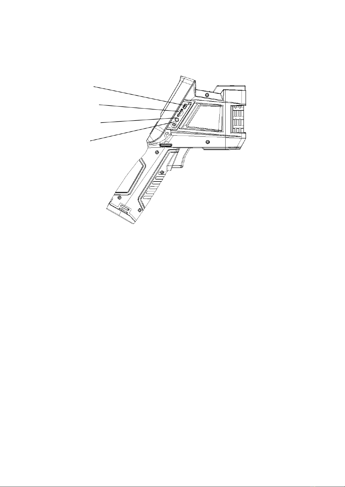
2.2 Interface
1
2
3
4
6

[1] USB Interface
The interface is for internal debugging.
[2] TF Card Slot
Adopt standard TF card, e.g. 8G TF card configured at random, for device upgrading
and image saving.
[3] Video Output
For video and audio output.
[4] Power Interface
External power input interface. DC12V power requirement. Positive central plug.
Attentions: Do not plug the audio cable into the power
interface,this will cause damage to the metal pin of the
power supply,the external power can’t be used.
3 Basic Operation
3.1 Battery Installation and Replacement
3.1.1 Battery Loading/Unloading
Battery cartridge is in the handle of the device. Push the push button at the bottom of the
battery cover, switch out the battery buckle, and loaded or unloaded the battery.
7
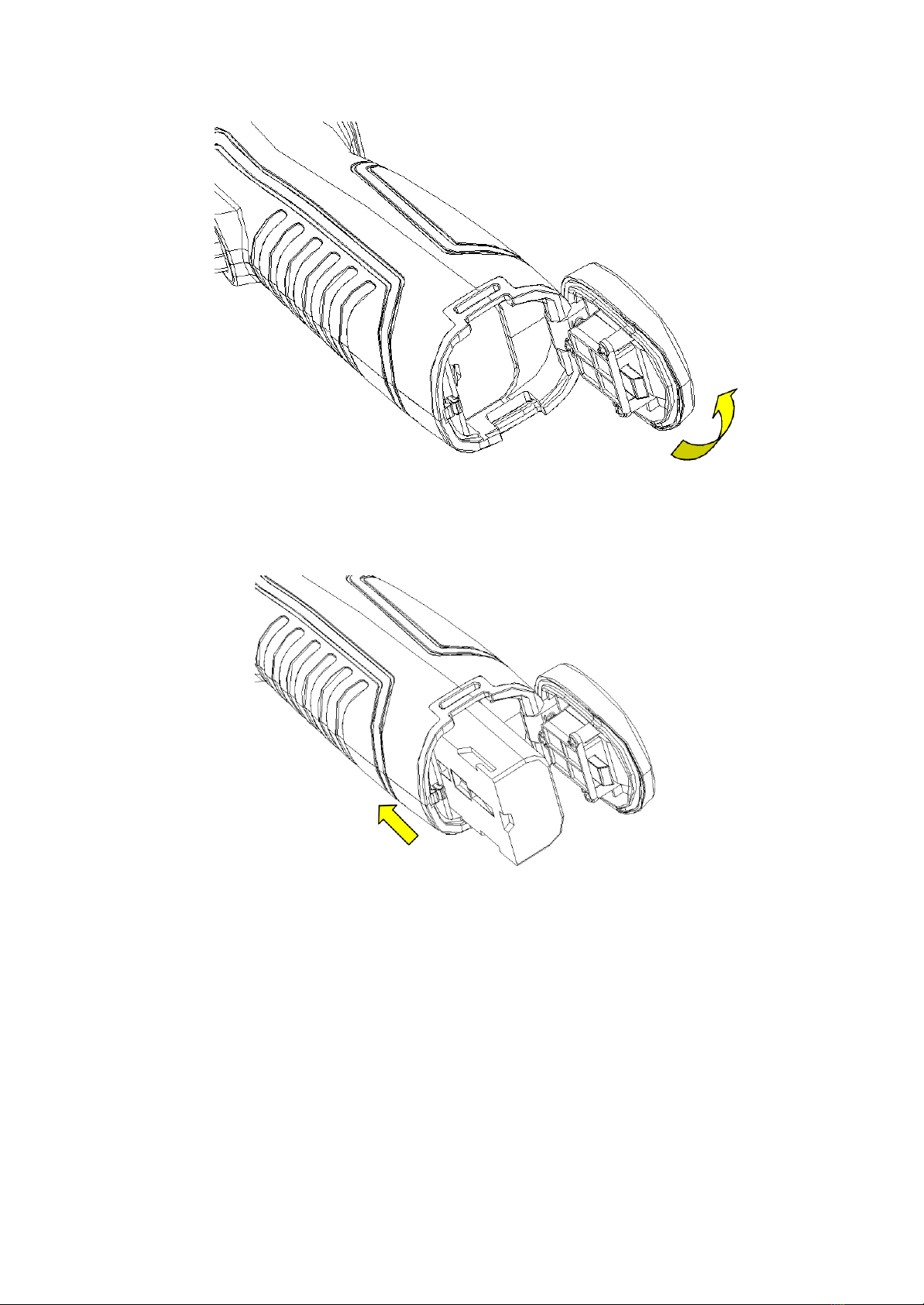
When inserting the battery, please note that the end with contact spot should be inserted
into the battery compartment first.
Close the battery cover. and use the device after hearing a "snap".
8

! Note: The device should adopt standard batteries, otherwise the mechanical or
electrical performance of the device may be damaged due to incorrect battery size or
voltage.
3.1.2 Battery Replacement
When showing empty battery and blinking for about 1 minute and 50 seconds, the
device displays battery low prompt message, and will automatically shut down after
about 10 seconds.
Shutdown Prompt
Replace the battery now.
9

3.2 General Instructions on Safe Battery Use
➢The battery should be stored in the environment at a temperature between -20℃-
20℃, due to slight self discharge phenomenon during storage of battery, to avoid
over discharge that may occur during storage and affect the battery capacity, the
battery should be fully charged for storage and charged regularly. The following
intervals should be adopted:
Ambient temperature is-20℃-20℃. Once every6 months;
Ambient temperature is20℃-45℃. Once every3 months;
Ambient temperature is45℃-60℃. Once every1 months.
The amount charged each time must exceed 50% of the battery capacity.
➢Battery should be charged at the environment temperature between0 ℃-40 ℃;
charging at the ambient temperature of 0℃will decrease the battery capacity;
charging at ambient temperature of over 40℃may cause over temperature and
damage.
! Warning:
! Do not disassemble, extrude or stab the battery;
! Do not short circuit the external contacts of the battery;
! Keep the battery dry. Do not put it in fire or water;
! Do not put it in any place easily accessible to children;
! Please dispose waste batteries in accordance with regulations of local government.
3.3 Quick Start
3.3.1 Acquiring Thermal Image
At the completion of battery installation, press the power switch of the thermal
imager (for over 3 seconds) until the display of power-on screen. After about 50
10

seconds, the device is initialized and enters the working status.
Open the lens cap, aim at the black body from 2 meters away, and adjust the
focal length of the lens of the thermal imager, to make the target image clear.
Press "A" button for automatic calibration, to obtain favorable thermal image.
! Note: Unsharp focusing will lead to wrong measurement.
3.3.2 Monitoring Point Setting
Press Up button among the direction buttons, to pop out the monitoring point
setting box. The options below are available: black body area setting, shielding
area setting, reset, amplitude-comparison factor and black body temperature.
Press the direction button to select the black body area setting option, press the
middle OK button to set the black position, and adopt the up, down, left and right
direction buttons to move the red box to the black body, with the red cursor aiming
at the center of the black body target as much as possible. Press the middle OK
button after selection. The box will turn blue at the completion of selection.
Press the direction button to select the shielding body area setting option, press
11

the middle OK button to set the shielding area, and adopt the up, down, left and
right direction buttons to move the red box to the position requiring temperature
shielding. Press the middle OK button after selection. The system can provide
three shielding areas in total. Press A button to switch the three shielding areas
for setting of position size. When the shielding area is selected, press S button
to switch the position or size adjustment mode, and C button to delete the
shielding area.
After setting, press C button to quit the monitoring point setting box.
3.3.3 Thermal Image Saving
To save the current thermal image acquired, choose one of the four ways below:
Press OK button to pop out the floating panel menu, select the "Take Photo"
option in the menu, and the system will save the image automatically.
Press "S" button, and press this button again to save after the image is frozen.
Press "S" button continuously for 3 seconds to save the image automatically.
Press the Shortcut button to save the image by setting the shortcut as the
"Take Photo" option.
3.3.4 Thermal Image Playback
There are two ways to open a file:
1、Press OK button to activate the main menu, and select the file in the sub-menu of
the "File Management" menu (Select by up, down, left and right buttons).
2、Click the "Preview" option in the floating panel, to open the file for options
(Switch options by left and right keys).
When the image is opened, replace the current image saved by up and
low buttons in the playback control panel.
Press cancel button, to exit the playback status and return to the real-time
12

temperature measurement status.
3.3.5 Export of Saved Information
Handle the contents saved in TF card with a card reader, including image export,
deletion, format and other operations.
! Note: It is recommended to adopt the formatting function in the firmware software
of the thermal imager to format the TF card.
3.3.6 LCD Setting
Two setting methods: 1. Set the brightness of LCD screen by "LCD Brightness
Adjustment" option in the general setting menu in the main menu, to achieve the
best display effect. 2. Set the shortcut button as "LCD Brightness Adjustment"
option, to set the brightness of the LCD screen.
3.3.7 Menu Operation Instruction
Keyboard operation: Press "OK" button to pop out the floating panel. Select the
icon by left and right buttons on the floating panel, and press "OK" button to enter
relevant interface.
Main menu interface: select the menu icon by "Up, Down, Left and Right" buttons,
and press OK button to enter sub-menu.
Sub-menu interface: select by "up" and "down" buttons. If there is a ">" tag, right
click to enter sub-menu.
Parameter interface: press "up" and "down" buttons to modify, and press "left" and
"right" buttons to select.
< > refer to modify the setting in the current menu
Press "OK" button to confirm the modification, save and return to the previous
menu, press "C" button to cancel the modification and return to previous menu.
button is to cancel and return to the previous menu; button is to
save and return to the previous menu. (For touch screen)
It is a switch button. Change the switch settings by left and right buttons.
13

4 Operation Guidance
4.1 Operation Interface Description
4.1.1 Graphic Interface of Working Status Screen of Thermal
Imager
20
19
18
17
16
15
14
13
1
12
2
3 11
4 10
9
8
5
7
6
Graphic Interface of Working Status Screen of Thermal Imager
[1] Power Icon: function icon.
[2] Emissivity: Default emissivity set.
[3] Reference Temperature Measurement :Fixed temperature measurement for
reference.
[4] Temperature Measurement Results: Display the temperature value of the
temperature measurement object (If the reference temperature measurement is set, the
difference with the reference temperature measurement will be displayed).
[5] Point Temperature Measurement Icon: Point temperature measurement cross
cursor.
[6] System Time: The system time displayed by the current device.
14

[7] Minimum Temperature:The minimum temperature value of the color code.
[8] Auto-Enhance: Select auto enhance mode.
[9] Manual Enhance: Select manual mode.
[10] Color Code: Color code bar. Press up and down buttons to switch the color code
bar.
[11] Bluetooth: enable Bluetooth function.
[12] Maximum Temperature: The maximum temperature value of the color code.
[13] Battery Status: Display the current battery level. The scales of battery
indicate different battery levels.
[14] TF Capacity:Display the TF card capacity used.
[15] Frozen Icon:indicate that the image is frozen currently.
[16] Zoom Out Icon:indicate that the image is enlarged currently.
[17] Video Recording Icon: indicate that the current status is video recording status.
[18] Continuous image capture Icon:indicate that the current status is
continuous image capture status.
[19] Audio Recording Icon: indicate that the current status is audio recording status.
[20] Zeroing Icon:indicate that the current device is zeroing.
! Note: As different models or modes have different functions, different models or
modes may not display all the tags in the interface.
15
Table of contents


