BOLIY PRO3600SI User manual
DIGITAL GENERATOR
DSP TECHNOLOGY
BOLIY
MODEL
Pro3600Si
Pro3600Si/E
Electric Start
Pro3600Si/ER
Remote Start

Introduction...................................................................... 1
Warranty ...........................................................................2-3
Safety Information...........................................................4
Exhaust Fumes are Poisonous
Never Run Generators Indoors
Fuel is Highly Flammable and Poisonous
Engine and Muffler May be Hot
Electric Shock Prevention
Connection Notes
Extension Cord Notes
Control Function..............................................................5-6
Description and Control Panel Key
Oil Warning System
Engine Switch
DC Protector
Handle Function ..............................................................7
Remote Start Function....................................................8
Pre-Operation Check.......................................................9
Fuel System
Refueling and Fuel Level Gauge
Engine Oil
Ground (Earth)
Operation..........................................................................10-13
Starting the Engine
Economy Control Switch
Application Range
Connection
Stopping the Engine
Periodic Maintenance......................................................14
Maintenance Chart
Spark Plug Inspection.....................................................15
Engine Oil Replacement
Fuel Filter
Fuel Tank Filter
Troubleshooting ..............................................................16
Engine Won’t Start
Generator Won’t Produce Power
Storage
Draining Fuel
Engine
Specifications ..................................................................17
Wiring Diagram ................................................................18
Grounding Information ...................................................19
Portable Generator Hazards...........................................20
High Altitude Jetting (4,000 Feet and Over) ..................21
PLEASE READ ENTIRE MANUAL BEFORE OPERATING
TABLE OF CONTENTS
1
INTRODUCTION
Congratulations on your new BOLIY Generator. This manual covers operation and
maintenance of the Pro3600Si/E generator, as well as basic troubleshooting. If you have any questions
regarding your machine, please consult your BOLIY dealer.
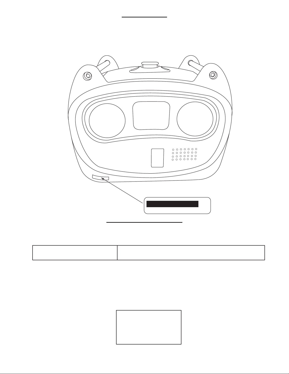
MACHINE IDENTIFICATION
MODEL SERIAL NO.
Record your generator model and serial number in the spaces provided to assist you in ordering
spare parts from a BOLIY dealer. Record and keep these I.D. numbers in a separate place in
case your machine is lost or stolen.
xxx-xxxxx
Pro3600 SI & Si/E
OWNER’S MANUAL
All rights reserved.
www.boliyusa.com

2
1 YEAR FULL FUNCTIONALITY &
2 YEAR EMISSIONS COVERAGE
BOLIY USA WARRANTY POLICY
This warranty is limited to Boliy products when distributed by Boliy USA. The warranty is effective from the date of retail
purchase and applies only to products used in recreational applications.
Warranty Contact Information:
Boliy USA
6800 Otter Lake Road
Lino Lakes, MN 55038-4428
To Qualify for This Warranty:
The product must be purchased in the United States from
Boliy USA or a Boliy dealer authorized to sell these
products. This warranty applies to first retail purchaser and
each subsequent owner during the applicable warranty time
period.
Coverage:
Boliy USA will repair or replace, at its option, any part or
unit that is proven to be defective in material or workman-
ship under normal use during the applicable warranty time
period . Warranty repairs and replacements will be made
without charge for parts or labor. Anything replaced under
warranty becomes the property of Boliy USA. All parts
replaced under warranty will be considered as part of the
original product, and any warranty on those parts will ex-
pire coincident with the original product warranty.
To Obtain Warranty Service:
1) Contact Boliy USA with date of purchase information
and description of problem to obtain warranty authoriza-
tion.
2) After warranty authorization has been established at our
option, the unit is to be sent to the National Service Center
(see address below) or an authorized service center.
Boliy USA Service
6800 Otter Lake Road
Lino Lakes, MN 55038
1-877-407-1457 or 651-407-1457
8:00 am - 5:00 pm Central
To Obtain Emissions Warranty:
After the potential of an emissions problem has been es-
tablished and warranty has been authorized at our option,
the generator will be picked up, repaired, and sent back at
no charge to the customer or the unit may be brought to a
qualified repair facility for emissions repair at no charge to
the customer.
Boliy USA Service
6800 Otter Lake Road
Lino Lakes, MN 55038
1-877-407-1457 or 651-407-1457
Exclusions:
This warranty does not extend to parts affected or damaged
by collision, normal wear, fuel contamination or deteriora-
tion, use in an application for which the product was not
designed or any other misuse, neglect, incorporation or use
of unsuitable attachments or parts, unauthorized alteration,
or any causes other than defects in material or workman-
ship of the product. Any product that has ever been de-
clared a total loss or sold for salvage by a financial institu-
tion or insurer.
Disclaimer of Conseqential Damage and Limitation of
Implied Warranties:
Boliy USA disclaims any responsibility for loss of time
or use of the product, transportation , commercial loss, or
any other incidental or consequential damage. Any implied
warranties are limited to the duration of this written limited
warranty. Some states do not allow limitations on how long
an implied warranty lasts and/or do not allow the exclusion
or limitation of incidental or consequential damages, so the
above exclusions and limitations may not apply to you .
This warranty gives you specific legal rights, and you may
also have other rights which vary from state to state.
BOLIY

3
Q. What costs are my responsibilities during the
warranty period?
A. The customer’s responsibility includes non-
warranty repairs, accident damages, and all costs
of normal maintenance service such as oil and
spark plugs.
Q. What are some examples of “abnormal” strain,
neglect, or abuse?
A. These terms are general, as it would be impos-
sible to provide a complete list. Some specific
examples include: Running the machine out of
oil; lack of proper maintenance; or operating the
machine with a broken or damaged part which
causes another part to fail. If you have any
specific questions on operation or maintenance,
please contact your dealer for advice.
Q. Does the warranty cover incidental costs such as
transportation due to a failure?
A. If it is determined that it is an emmissions re-
lated problem the warranty will cover this cost.
However, if the warranty claim is not emissions
related, these costs are not covered.
Q. May I perform any or all of the recommended
maintenance shown in the Owner’s Manual
instead of having the dealer do them?
A. Yes, if you are a qualified mechanic and fol-
low the procedures specified in the Owner’s and
Service Manual. We do recommend, that items
requiring special tools or equipment be done by
a BOLIY generator dealer.
Q. Will the warranty be void or cancelled if I do not
operate or maintain my new BOLIY exactly as
specified in the Owner’s Manual?
A. Yes. The warranty on a new BOLIY can be
“voided” or “cancelled”.
If a particular failure is caused by operation or
maintenance other than as shown in the Owner’s
Manual, that failure will not be covered under
warranty.
Q. What responsibility does my dealer have under
this warranty?
A. Each BOLIY generator dealer is expected to:
1. Check the operation of the generator before sale.
2. Explain the operation, maintenance, and
warranty requirements to your satisfaction at the
time of sale, and upon your request at any later
date.
CUSTOMER SERVICE
If your generator isn’t functioning or encounter
technical problems, our authorized team of techni-
cians is available to help you get your Boliy Gen-
erator back up and running as quickly as possible.
To take full advantage of our service center please
choose one of the following options for your repair:
1) For the fastest service, you may exchange your
unit for a ready-to-go unit of equal age and
condition. A $500 deposit will be required and will
be refunded when the defective unit is returned. All
replacement units will be shipped within 24 hours.
2) Return your defective unit and it will be repaired
within 10 days and returned to you at no charge.
CHANGE OF ADDRESS
The federal government requires each manufacturer
to maintain a complete, up-to-date list of all first
purchasers against the possibility of a safety-related
defect and recall. This list is compiled from the
purchase registrations sent to BOLIY. If you should
move after you have purchased your new generator,
please advise us of your new address by sending a
post-card listing your BOLIY model name, engine
number, and dealer name as it is shown on your
warranty identification, your name and new mailing
address. Mail to:
BOLIY USA
6800 Otter Lake Road
Lino Lakes, MN 55038-4428
Contact Number: 651-407-1457
This will ensure that BOLIY has an up-to-date
registration record in accordance with federal law.
WARRANTY FAQ

4
SAFETY INFORMATION
EXHAUST FUMES ARE POISONOUS. Never operate the engine in an enclosed area. Uncon-
sciousness and death will result. Always operate the engine in a well ventilated area.
NEVER RUN GENERATORS INDOORS OR IN CONFINED SPACES.
• Never sleep near a running generator due to the emission of carbon monoxide.
• When working with a generator, keep at least 20 feet away from where it is running.
• Keep generators clear of all fresh air inlets (houses, buildings, campers, or tents) to avoid possible carbon
monoxide poisoning.
Failure to follow these precautions could result in POISONING or DEATH.
FUEL IS HIGHLY FLAMMABLE AND POISONOUS
• Always turn off the engine when refueling.
• Never refuel while smoking or in the vicinity of an open flame.
• Take care not to spill any fuel on the engine or muffler when refueling.
• If you swallow any fuel, inhale fuel vapor, or allow any to get in your eyes, see your doctor immediately. If
any fuel spills on your skin or clothing, immediately wash with soap and water and change your clothes.
• When operating or transporting the machine, be sure it is kept upright. If it tilts, fuel may leak from the carbu-
retor or fuel tank.
ENGINE AND MUFFLER MAY BE HOT
• Place the machine in a place where pedestrians are not likely to touch the machine and away from children.
• Avoid placing any flammable materials near the exhaust outlet during operation.
• Keep the machine at least 1 meter/3 feet from buildings or other equipment, or the engine may overheat.
• Never operate the engine with the dust cover.
ELECTRIC SHOCK PREVENTION
• Never operate the engine in rain or snow.
• Never touch the machine with wet hands.
• Be sure to ground (Earth) the generator
NOTE: USE A GROUND (Earth) LEAD OF SUFFICIENT CAPACITY. (SEE PAGE 17)
CONNECTION NOTES
Avoid connecting the generator to a commercial power outlet. Never connect the generator in parallel with any
other generator.
Before the generator can be connected to a building’s electrical system, a licensed electrician
must install an isolation (transfer) switch in the building’s main fuse box. The switch is the
connection point for generator power and allows selection of generator or main line power to
the building. This will prevent the generator from charging the main power line (backfeeding)
when the main power supply has failed or has been turned off for line repair. Backfeeding can
electrocute or injure line maintenance personnel. Also, generator and building electrical sys-
tem damage can occur when normal operating power returns if unit is used without an isola-
tion switch.
EXTENSION CORD NOTES
• When using an extension cord, total cord length should not exceed 50 feet of 12 gauge wire or 100 feet of
10 gauge wire.
• Extension cord should be protected by a tough, flexible rubber sheath (IEC 245) or the equivalent to with-
stand mechanical stresses.
WARNING
WARNING

5
ONOFF
(P US H)
PROTECTOR
ON
STOP
ECON
ON
OF F
AC
TO RESE TAC
RESTAR
T EN G INE
1
231
10
11
12
13
14
15
4
56
789
DIGITAL
TECH
ENGINE
START
16
ON
OFF
CONTROL FUNCTION
Description and Control Panel Key
1. Carrying Handles
2. Fuel Level Gauge
3. Fuel Cap
4. Fuel On/Off Switch
5. AC Ready Pilot Light
6. Oil Warning Light
7. Ground (Earth) Terminal
8. 30 Amp RV Receptacle
9. 20 Amp Receptacle
10. Engine On/Off Switch
11. Choke Knob
12. Economy Control Switch
(SMART throttle switch)
13. Recoil Starter
14. DC Outlet and Reset Button
15. Oil Fill Access Door Panel
16. Engine Start button

6
CONTROL FUNCTION CONTINUED
OIL LIGHT & WARNING SYSTEM
If the oil level falls below the safe operating level, the engine will stop automatically. Unless you refill
with oil, the engine will not start again.
NOTE:
If the engine stalls or does not start, turn the engine switch to “ON” position and then pull the recoil starter.
If the oil warning light flickers for a few seconds, the engine oil is low. Add oil and restart.
ENGINE SWITCH
The engine switch controls the ignition system.
A. Ignition circuit is switched on.
The engine can be started.
B. Ignition circuit is switched off.
The engine will not run.
12 Volt Charger
The DC Protector turns off automatically when the load exceeds the generator’s rated 12 volt charging
output.
NOTE:
If the DC Protector trips to the OFF position, press to reset. Reduce the load to the specified 8 amp 12-volt
generator output. If it turns off again, consult the authorized dealer.
PROTECTOR
(PUSH)
ON OFF
7
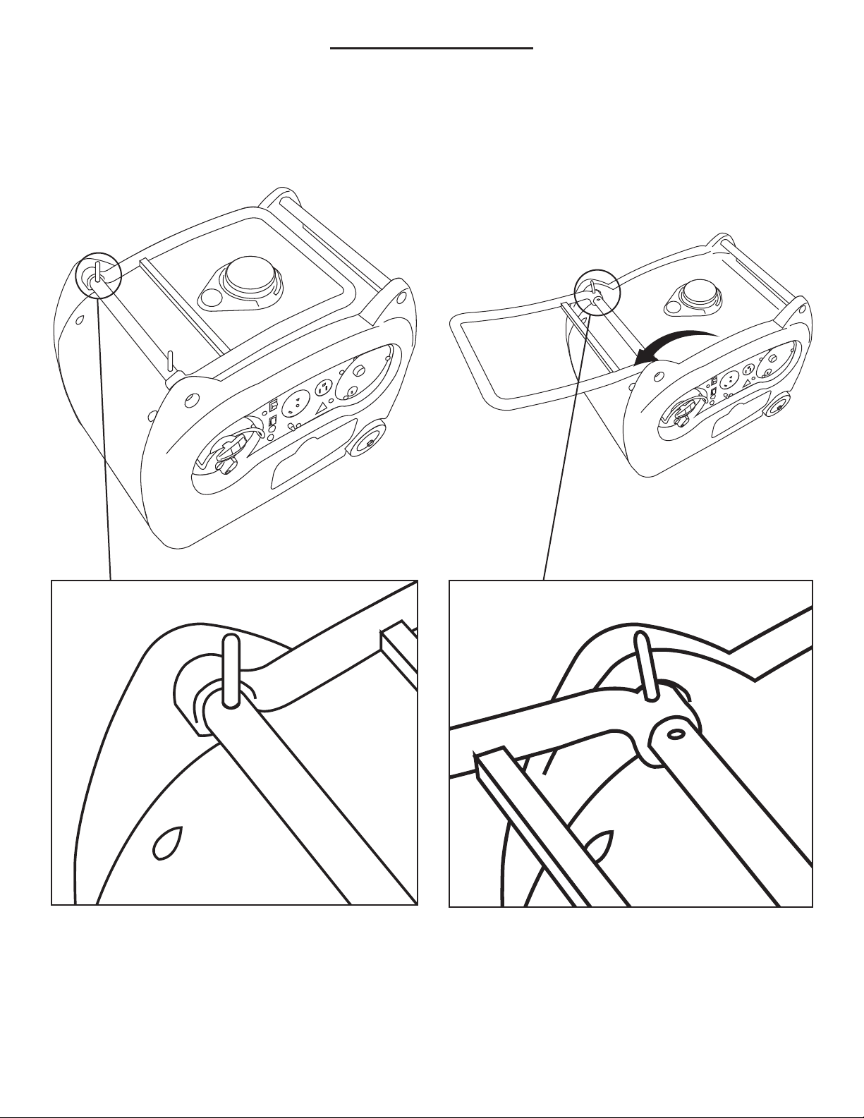
HANDLE FUNCTION
Pin location when the handle is stowed. Pin location to lock the handle.

8
REMOTE START/STOP FUNCTION
ONO FF
(P US H)
PROTECTOR
ON
STOP
ECON
ON
OF F
AC
TO RESE TAC
RESTART EN GINE
DIGITAL
TECH
ENGINE
START
ON
OFF
ONO FF
START
ON
(P US H)
PROTECTO
R
DIGITA
L
TE
C
ENGINE
START
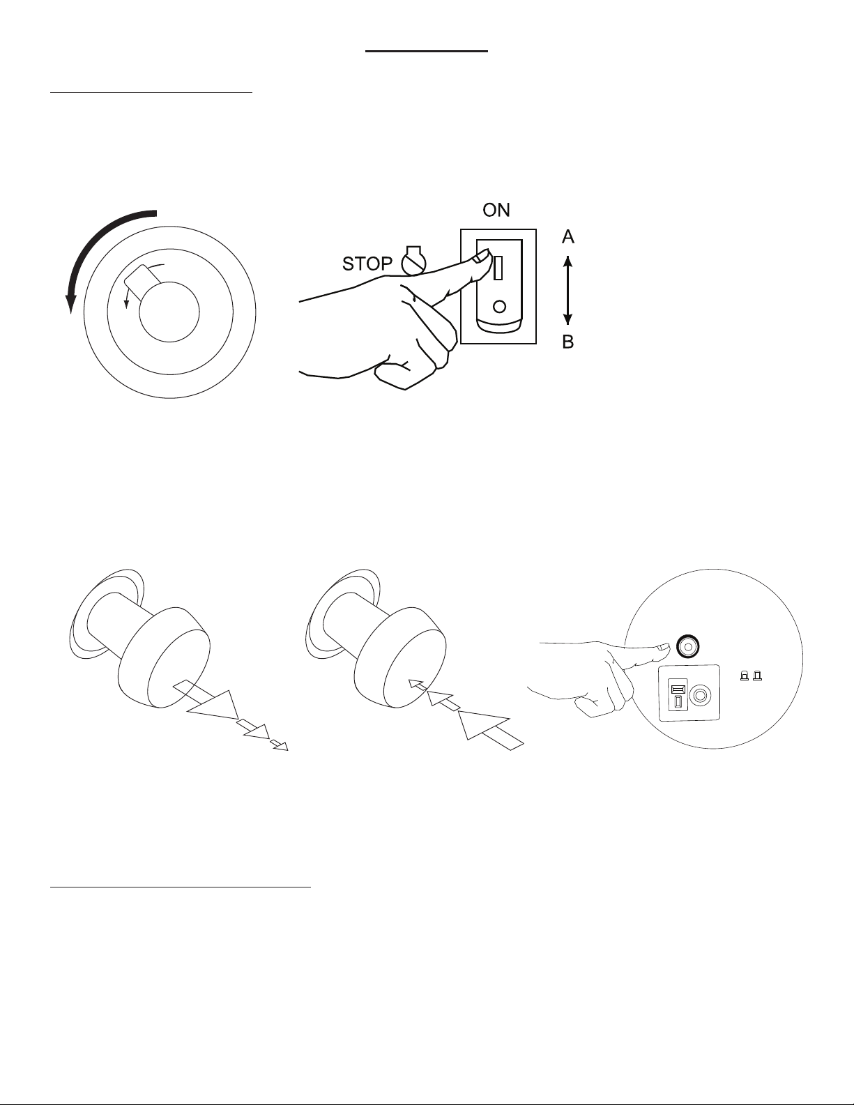
1) Turn the fuel knob to “On”.
2) Turn the engine kill switch
to “On”.
3) Turn the key switch to
“On”. Remote start will not
work if key switch is not in
the “On” position.
4) To start the engine remotely, push unlock
button twice on the remote. If the rst at-
tempt fails, push the unlock button again.
5) To shut o the generator, push the lock
button on the remote.
6) If the generator will not be used again for
more than a day, turn the key switch to the
“O” position.
Failure to turn the key switch o aer use will
drain the battery.

9
PRE-OPERATION CHECKLIST
NOTE:
Pre-operation checks should be made prior to each use.
FUEL SYSTEM
Make sure there is sufficient fuel in the tank.
Recommended fuel: Unleaded gasoline
Fuel tank capacity: Total 1.9 US Gallons
The engine must use regular unleaded gasoline with a pump octane number ((R + M)/2) of 86 or higher, or research
octane number of 91 or higher. E-85 is NOT recommended.
REFUELING AND FUEL LEVEL GAUGE
To refuel, remove cap and add fuel slowly until fuel gauge indicates full. Apply fuel cap and turn fuel vent to
the ON position.
• Fuel is highly flammable and poisonous. Read “SAFETY INFORMATION” before refueling.
• Do not fill above the top of fuel filler or it may overflow when the fuel heats and expands
• Wipe up any spilled fuel immediately
• After refueling, make sure the tank cap is tightened
ENGINE OIL
Make sure the engine oil is at the upper level of the oil filler hole. Add oil as necessary.
Recommended oil for most climates: 10W30
For extremely cold conditions the oil viscosity may be lowered to ease starting: 5W30
Engine Oil Quantity: 0.63 US qt
NOTE:
Recommended engine oil classification: API Service “SE” or “SF”; if not available, “SD”.
The generator has been shipped without engine oil. Fill with oil or it will not start.
GROUND (EARTH)
Make sure to ground (Earth) the generator. SEE PAGE 19.
WARNING
“F” Full
“E” Empty
E
F
E
F
Fuel Level Gauge
CAUTION
10
OPERATION
STARTING THE ENGINE
NOTE:
Before starting the engine, do not connect any electric devices.
1. Turn the fuel switch lever to the “ON” position.
2. Turn the engine switch to the “ON” position.
3. Hold the choke knob fully out for a cold start.
Note: Sometimes the choke is required to start a warm engine.
4. Pull slowly on the recoil starter until it is engaged, then pull it briskly. (Electric start model press engine
start button to start.)
5. After the engine starts, warm up the engine until the engine does not stop when the choke knob is returned
to the original position.
6. Push the choke knob back to the original position.
NOTE:
When starting the engine in areas where the ambient temperature is below 0°/32° F run the engine for one
to three minutes to warm up the engine.
ECONOMY CONTROL SWITCH
Engine speed is kept at idle automatically when the electrical device is disconnected and is returned to the
proper speed by the electrical load when the electrical device is reconnected. The economy control switch
in “ON” position is recommended to minimize the fuel consumption while in normal operation.
NOTE:
When high electrical load devices are connected simultaneously, turn the economy control switch to the
“OFF” position, the engine speed will increase to reduce voltage changes. Otherwise the generator will not
operate sufficiently to run high demand electrical devices.
CHOKE
NO
NO
NO
CHOKE
OFF
OFF
OFF
ON OFF
1. 2.
3. 6.
DIGITAL
DIGITAL
TECH
TECH
PROTECTOR
(PUSH)
ON OFF

11
OPERATION CONTINUED
AC CONNECTION
ALTERNATING CURRENT (AC)
• Be sure electric devices including the lines and plug connections are in good condition
before connection to the generator
• Be sure any electric devices are turned off before plugging it in
• Be sure the total load is within generator rated output
• Be sure the receptacle load current is within receptacle rated current
1. Wind the power lead 2 or 3 turns around the carrying handle.
2. Start the engine.
3. Plug in to the AC receptacle.
4. Make sure the AC indicator light is on.
5. Turn on any electric devices.
Note: The highest peak load on this model is 3600 watts, the short term peak load is 3300 watts and the
max operating load is 3,000 watts. High temperatures or high elevations will reduce the expected perfor-
mance of this generator.
OVERLOAD INDICATOR LIGHT
The overload indicator light (the AC pilot light) will flash when an overload of connected electrical device
is detected or the inverter control unit overheats. The electronic breaker will then activate, stopping power
generation in order to protect the generator and any connected electric devices, but the engine will not stop
running.
When the overload indicator light comes on and power generation stops, proceed as directed:
1. Turn off any connected electric devices and stop the engine.
2. Reduce the total wattage of connected electric devices within the application range.
3. Check for blockages in the cooling air inlet and around the control unit. If any blockages are found, remove.
4. After checking, restart the engine.
NOTE:
The generator AC output automatically resets when the engine is stopped and restarted.
USING THE GENERATOR FOR BATTERY CHARGING
Do not use AC and DC power at the same time or the generator may be damaged.
NOTE:
The generator DC rated voltage is 8 Amps at 12 Volts.
1. Start Engine
2. Plug in battery charge wires to D.C. receptacle- #14 on CONTROL FUNCTION DIAGRAM
NOTE:
• Make connections to the battery after starting the engine
• Clamp the red wire to the positive (+) terminal and the black wire to the negative (-) terminal of the
battery. Do not reverse these positions.
CAUTION
CAUTION

12
OPERATION CONTINUED
• Be sure the battery leads are properly connected and are not damaged or obstructed.
• Reduce the load to the specified generator rated output if the DC protector turns off. If it
turns off again, consult the authorized dealer.
NOTE:
• If a short or overdraw should occur in the system, it will cause the DC Protector to trip. Press to reset
the DC protector.
NOTE:
• At full charge, electrolyte specific gravity is between 1.26 and 1.28
• Check specific gravity hourly.
Never smoke near the battery while charging. Do not make or break connections while the
battery is charging. This may cause sparks to ignite the battery gas. Battery acid is poisonous
and dangerous; it contains sulfuric acid. Avoid contact with skin, eyes, and clothing as it will
cause severe burns.
If contact occurs:
EXTERNAL – Flush with water.
INTERNAL – Drink large quantities of water or milk, then drink milk of magnesia, beaten
egg or vegetable oil. Call physician immediately.
EYES – Flush with water for 15 minutes and get prompt medical attention.
Batteries produce explosive gases. Keep sparks, flame, cigarettes, etc., away from the generator.
Ventilate when charging or using in closed space. Always wear eye protection when working near
batteries. KEEP OUT OF REACH OF CHILDREN.
STOPPING THE ENGINE
NOTE:
1. Disconnect any electric devices.
2. Turn the engine switch to the “STOP” position.
3. Turn the fuel lever to “OFF”
CAUTION
WARNING
1.
STOP
ON
OFF
2. 3.

13
NOTE:
• Application wattage indicates when each device is used by itself
• Be sure the total load is within generator rated output otherwise generator damage may occur.
• Do not use AC and DC power at the same time or the generator may be damaged.
NOTE:
Some precision equipment is voltage sensitive and may require a more uniform voltage supply than portable genera-
tors provide. Examples include some medical equipment, personal computers, and some inverters that sense peak and
RMS voltage values. Consult the precision-equipment vendor before relying on any portable generator to provide
power to such equipment.
CAUTION
Household RV
Coffee Maker 1750 1750
Dishwasher
- Cool Dry 700 1400
Electric Fry Pan 1300 1300
Electric Range
- 8 - inch element 2100 2100
Microwave Oven 1000 2100
20” Box Fan or Table Fan 120 180
Electric Blanket 150 150
Refrigerator 192 1200
Automatic Washer 1150 2300
Clothes Dryer
- Electric 5750 1800
Furnace Fan, gas or fuel oil
1/8 Horsepower 300 500
1/4 Horsepower 600 1000
1/2 Horsepower 875 2350
Lights (as indicated on bulb)
Radio 50-200 50
Sump Pump
1/3 Horsepower 800 1300
1/2 Horsepower 1050 2150
Television
- Color 300 300
RV Air Conditioner
13,500 BTU 1800 2800
Room Air Conditioner
10,000 BTU 1500 2200
Contractor
Air Compressor
- 1 Horsepower 1500 4500
Bench Grinder
- 8 inches 1400 2500
Hand Drill
- 1/2 inch 600 600
High-Pressure Washer
- 1 Horsepower 1200 3600
Circular Saw, Heavy Duty
- 7 1/4 inches 1400 2300
Household RV
Electric Chain Saw
- 14 inches, 2 HP 1100 1000
Table Saw
- 10 inches 1800 4500
Drills
- 3/8 inch, 4 amps 440 600
- 1/2 inch, 5.4 amps 600 900
Capacitor Start Induction Run
- 1/3 Horsepower 720 1300
- 1 Horsepower 1600 4500
Capacitor Start Capacitor Run
- 1 1/2 Horsepower 2000 6100
Fan Duty
- 1/6 Horsepower 550 850
Farm Equipment
Electric Fence, 25 miles 250 230
Milk Cooler 1100 1800
Milker (vacuum pump)
- 2 Horsepower 1000 2300
Portable Heater (kerosene, diesel fuel)
- 50,000 BTU 400 600
- 90,000 BTU 500 725
-150,000 BTU 625 1000
Battery Charger
- 15 amp 380 380
- 60 amp/250-amp boost 1500/5750 1500
- 100 amp/300-amp boost 2400/7800 2400
Electric Welder
- 200 amp AC 9000 9000
- 230 amp AC, at 100 amp 7800 7800
Air Compressors
- 1/2 Horsepower 975 1600
- 1 Horsepower 1600 4500
Computers
- Desktop 600 to 800 600
- Laptop 200 to 250 200
- Monitor 200 to 250 200
Fax 600 to 800 600
Printer 400 to 600 400
OPERATION CONTINUED
APPLICATION RANGE: APPROXIMATE WATTAGE REQUIRED FOR STARTING

14
PERIODIC MAINTENANCE
MAINTENANCE CHART
Regular maintenance is most important for the best performance and safe operation.
Stop the engine before starting maintenance work.
Item Remarks Pre-Operation
Check (Daily)
First Month
/ 20 Hours
Every 3 Months
/ 50 Hours
Every 6 Months
/ 100 Hours
Every 12
Months
/ 300 Hours
Spark Plug
Check condition. Adjust
gap and clean. Replace if
necessary.
X
Engine Oil Check oil level/ Replace X
Air Filter Clean/Replace if
necessary. XX
Fuel Filter
Clean fuel cock and fuel
tank filter. Replace if
necessary.
X
Value Clearance Check and adjust when
engine is cold. X
Fuel Line
Check fuel hose for crack
or damage. Replace if
necessary.
XX
Exhaust System
Check for leakage.
Retighten or replace
gasket if necessary.
X
Check muffler screen.
Clean/ replace if
necessary.
X
Choke Handle Check choke’s operation. X
Cooling System Check fan damage. X
Starting System Check recoil starter
operation. X
Decarburization More frequently if
necessary. X
Generation Check the pilot light
comes on. X
Fittings/Fasteners
Check all fittings and
fasteners. Correct if
necessary.
X
Use only genuine BOLIY replacement parts. If you have questions, contact your dealer
or Boliy USA (651-407-1457)
WARNING
CAUTION

15
SPARK PLUG INSPECTION
You should periodically remove and inspect the spark plug.
1. Check for discoloration and remove the carbon.
2. Check the spark plug type and gap.
Standard electrode color: Tan Color
Standard Spark Plug: BPR4ES (NGK) (F7RTC)
Gap: (0.028 – 0.031 inches)
3. Install the spark plug.
Spark Plug Torque: 14 lbs. – Ft.
ENGINE OIL REPLACEMENT
1. Place the machine on a level surface and warm up the engine. Then stop the engine.
2. Remove the rubber cap on the bottom.
3. Place an oil pan under the engine. Remove the drain bolt.
4. Open the oil filler cover as shown and remove the oil filler cap so
that the oil can be completely drained.
5. Check the drain bolt, gasket, oil filler gap and O-ring.
6. Reinstall the oil drain bolt. - Drain Bolt Torque: 12 Ft. lbs.
7. Add engine oil to the upper level.
• Recommended oil for most climates: 10W30
• For extremely cold conditions the oil viscosity may be lowered to ease starting: 5W30
• Engine Oil Quantity: 0.63 US qt
NOTE:
Recommended engine oil classification: API Service “SE” or “SF”
Be sure no foreign material enters the crankcase.
8. Install the oil filler cap.
9. Install the rubber cap on the bottom.
Be sure to install securely to prevent from falling off during operation.
10. Close the oil filler cover.
FUEL FILTER
Do not smoke or have an open flame in the vicinity of the fuel and solvent.
1. Stop the engine.
2. Clamp the fuel line with the clip.
3. Replace the fuel filter.
FUEL TANK FILTER
1. Remove the fuel tank cap and filter.
2. Clean the filter with solvent, if damaged, replace.
3. Wipe the filter and insert it.
Be sure the tank cap is securely tightened.
WARNING
WARNING
CAUTION
CAUTION
(0.028-0.031 inch)

16
TROUBLESHOOTING
ENGINE WON’T START
1. Fuel system, engine is not getting fuel..
• No fuel in tank… Supply fuel.
• Clogged fuel line… Clean fuel line.
• Foreign matter in fuel filter… Replace fuel filter.
• Clogged carburetor … Clean carburetor.
2. Engine oil light flashes
• Oil level is low… Add engine oil.
3. Electrical system
• Engine switch to “ON”. Poor or no spark.
• Spark plug is dirty… Replace spark plug.
• Faulty ignition system… Consult dealer.
4. Compression Insufficient
• Worn out piston and cylinder… Consult dealer.
GENERATOR WON’T PRODUCE POWER
Stop the engine, then restart. If A/C lights continue to flash consult your dealer.
STORAGE GUIDELINES
Long term storage of your machine will require some preventive procedures to guard against deterioration. The
following steps are necessary to protect your generator during long periods of storage.
DRAIN THE FUEL
1. Add fuel stabilizer to tank and run generator.
2. Remove the fuel tank cap. Drain the fuel from the fuel tank into an approved gasoline container using a
commercially available hand siphon. Then, install the fuel tank cap.
WARNING
• Fuel is highly flammable and poisonous.
• Wipe up any spilled fuel immediately.
3. Drain fuel from the carburetor by loosening the drain screw on the carburetor float chamber.
4. Turn the fuel cock lever to “OFF”. Start the engine and leave it run until it stops. This will burn any remain-
ing fuel in the carburetor.
ENGINE
1. Remove the spark plug, pour about one tablespoon of SAE 10W30 or 20W40 motor oil into the spark plug
hole and reinstall the spark plug. Turn over engine several times (with ignition off) to coat the cylinder walls
with oil.
2. Pull the recoil starter until you feel compression. Then stop pulling. (This prevents the cylinder and valves from rusting).
3. Clean exterior of the generator and apply a rust inhibitor.
4. Store the generator in a dry, well-ventilated place, with the cover placed over it.
5. The generator must remain in a vertical position when stored, carried or operated.

17
OVERALL LENGTH (in) 23
OVERALL WIDTH (in) 16.5
OVERALL HEIGHT (in) 18.5
DRY WEIGHT (lb..) 3600 SI - 68 lbs, 3600 SI/E - 74 lbs
SHIPPING WEIGHT (lb.) SI - 72lbs, SI/E -78lbs
FUEL TANK CAPACITY (US gal.) 1.9
NOISE LEVEL (1/4 load at 7m) 53-58 dB
GENERATOR
TYPE AC OUTPUT, Multistage permanent-magnet generator
RATED OUTPUT (WATTS) 3000
MAX OUTPUT (WATTS) 3300
FULL TANK OUTPUT (WATTS) 13500
RUN TIME AT 1/2 RATED LOAD 7.5 hours
RUN TIME AT RATED LOAD 4 hours
POWER CONVERSION RATE 85-92%
RATED VOLTAGE (V) 120 North America / 230 Europe
RATED FREQUENCY (Hz) 60 50
RATED CURRENT (A) 25 13
DC OUTPUT (12V/8A) YES
ENGINE
TYPE 166F, OHV, AIR-COOLED, 4 - STROKE
STARTING SYSTEM RECOIL START / ELECTRIC START
CYLINDER ARRANGEMENT INCLINED, SINGLE CYLINDER
BORE X STROKE (mm) 66 X 50
IGNITION SYSTEM CDI
SPARK PLUG TYPE BPR4ES (NGK) / F7RTC
GAP (in) 0.8 (0.028 - 0.031)
DISPLACEMENT 171CC
RATED OUTPUT (HP) r/min (4.9) / 3600
FUEL UNLEADED GASOLINE
ENGINE OIL QUANTITY (US qt) 0.63
THE FLUCTUATION OF VOLTAGE & FREQUENCY
INSTANTANEOUS 25%
STABLE STATE 0%
STABLE TIME (second) 3
FREQUENCY 0.2%
CHARACTERISTIC
AUTOMATIC RELEASE PRESSURE YES
ELECTRO-BREAKER YES
FUEL LEVEL GAUGE YES
ENGINE OIL WARNING LIGHT YES
OVERLOAD INDICATOR LIGHT NO
AC INDICATOR LIGHT YES
ENERGY CONSERVATION CURRENT IDLING YES
INSULATION CLASS F
BOLIY Pro 3600Si/ Pro3600Si/E Pro3600Si/ER DSP INVERTER GENERATOR
SPECIFICATIONS & DIMENSIONS

18
BOLIY Pro 3600Si & 3600Si/E DSP INVERTER GENERATOR WIRING DIAGRAM
Color code
B - Black
G - Green
L - Blue
O - Orange
R - Red
W - White
Y - Yellow
P - Pink
B/W - Black/White
G/Y - Green/Yellow
W/L - White/Blue
1 - Main coil
2 - Sub coil
3 - Control unit
4 - AC indicator light/
Overload indicator light
5 - AC receptacle
6 - Ground (Earth) terminal
7 - Economy Control Switch
8 - Step Motor controller
9 - Engine switch
10 - Oil warning light
11 - Oil warning unit
12 - Oil level gauge
13 - Ignition coil
14 - Spark plug
15 - AC-CDI unit
16 - Pulsar coil
17 - Stepping motor
18 - Charge coil
19 - DC receptacle
20 - Ballast
Other manuals for PRO3600SI
2
This manual suits for next models
2
Table of contents
Other BOLIY Portable Generator manuals


Popular Portable Generator manuals by other brands

Champion Global Power Equipment
Champion Global Power Equipment 100719 quick start guide

Amperes
Amperes CM1400 instruction manual

Champion Power Equipment
Champion Power Equipment CSA40036 Owner's Manual and Operating Instructions

Sincro
Sincro EW-DC Series Use and maintenance manual

Robin
Robin RGV12100 Instructions for use

Hyundai
Hyundai HY3800LE-LPG user manual


